Hangar 9 HAN3390 Manuale utente
- Categoria
- Giocattoli telecomandati
- Tipo
- Manuale utente
Questo manuale è adatto anche per

Aermacchi MB-339 60–85N
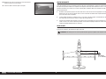
Instruction Manual
Bedienungsanleitung
Manuel d’utilisation
Manuale di Istruzioni
Scan the QR code and select the Manuals and Support quick links from the product
page for the most up-to-date manual information.
Scannen Sie den QR-Code und wählen Sie auf der Produktseite die Quicklinks
Handbücher und Unterstützung, um die aktuellsten Informationen zu Handbücher.
Scannez le code QR et sélectionnez les liens rapides Manuals and Support sur la
page du produit pour obtenir les informations les plus récentes sur le manuel.
Scannerizzare il codice QR e selezionare i Link veloci Manuali e Supporto dalla
pagina del prodotto per le informazioni manuali più aggiornate.
HAN3390 Updated 10/2022

2EN
NOTICE
All instructions, warranties and other collateral documents are subject to change at the sole discretion of Horizon
Hobby, LLC. For up-to-date product literature, visit horizonhobby.com or towerhobbies.com and click on the support
or resources tab for this product.
Age Recommendation: Not For Children Under 14 Years. This Is Not A Toy.
SAFETY WARNINGS AND PRECAUTIONS
Read and follow all instructions and safety precautions before use. Improper use can result in fi re, serious injury and
damage to property.
Components
Use only with compatible components. Should any compatibility questions exist, please refer to the product
instructions, component instructions or contact the appropriate Horizon Hobby offi ce.
Flight
Fly only in open areas to ensure safety. It is recommended fl ying be done at radio control fl ying fi elds. Consult local
ordinances before choosing a fl ying location.
Batteries
Always follow the manufacturer’s instructions when using and disposing of any batteries. Mishandling of Li-Po
batteries can result in fi re causing serious injury and damage.
Turbine Safety
Follow any turbine safety procedures as outlined in the manual for your particular turbine. Additional details can be
found at the AMA website. (https://www.modelaircraft.org/system/fi les/documents/510-A.pdf)
Small Parts
This kit includes small parts and should not be left unattended near children as choking and serious injury could result.
MEANING OF SPECIAL LANGUAGE
The following terms are used throughout the product literature to indicate various levels of potential harm when
operating this product:
WARNING: Procedures, which if not properly followed, create the probability of property damage, collateral damage,
and serious injury OR create a high probability of superfi cial injury.
CAUTION: Procedures, which if not properly followed, create the probability of physical property damage AND a
possibility of serious injury.
NOTICE: Procedures, which if not properly followed, create a possibility of physical property damage AND a little or
no possibility of injury.
WARNING: Read the ENTIRE instruction manual to become familiar with the features of the product before
operating. Failure to operate the product correctly can result in damage to the product, personal property and
cause serious injury.
This is a sophisticated hobby product. It must be operated with caution and common sense and requires some basic
mechanical ability. Failure to operate this Product in a safe and responsible manner could result in injury or damage
to the product or other property. This product is not intended for use by children without direct adult supervision. Do
not attempt disassembly, use with incompatible components or augment product in any way without the approval
of Horizon Hobby, LLC. This manual contains instructions for safety, operation and maintenance. It is essential to
read and follow all the instructions and warnings in the manual, prior to assembly, setup or use, in order to operate
correctly and avoid damage or serious injury.
SAFE OPERATING RECOMMENDATIONS
• Inspect your model before every fl ight to ensure it is airworthy.
• Be aware of any other radio frequency user who may present an interference problem.
• Always be courteous and respectful of other users in your selected fl ight area.
• Choose an area clear of obstacles and large enough to safely accomodate your fl ying activity.
• Make sure this area is clear of friends and spectators prior to launching your aircraft.
• Be aware of other activities in the vicinity of your fl ight path that could cause potential confl ict.
• Carefully plan your fl ight path prior to launch.
• Abide by any and all established AMA National Model Aircraft Safety Code.
BEFORE STARTING ASSEMBLY
• Remove parts from bag.
• Inspect fuselage, wing panels, rudder and stabilizer for damage.
• If you fi nd damaged or missing parts, contact your place of purchase.
• Charge transmitter and receiver batteries.
• Center trims and sticks on your transmitter.
• For a computer radio, create a model memory for this particular model.
• Bind your transmitter and receiver, using your radio system’s instructions.
NOTICE: Rebind the radio system once all control throws are set. This will keep the servos from moving to their
endpoints until the transmitter and receiver connect. It will also guarantee the servo reversal settings are saved in the
radio system.
IMPORTANT FEDERAL AVIATION ADMINISTRATION (FAA) INFORMATION
Use the QR code below to learn more about the Recreational UAS Safety Test (TRUST), as
was introduced by the 2018 FAA Reauthorization Bill. This free test is required by the FAA for all
recreational fl yers in the United States. The completed certifi cate must be presented upon request by
any FAA or law enforcement offi cial.
If your model aircraft weighs more than .55lbs or 250 grams, you are required by the FAA to
register as a recreational fl yer and apply your registration number to the outside of your aircraft. To
learn more about registering with the FAA, use the QR code below.

3 EN
Aermacchi MB-339 60–85N
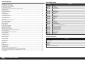
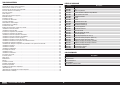
TABLE OF CONTENTS
Notice ......................................................................................................................................................................2
Meaning of Special Language ..................................................................................................................................2
Safety Warnings and Precautions .............................................................................................................................2
Safe Operating Recommendations ...........................................................................................................................2
Before Starting Assembly .........................................................................................................................................2
Important Federal Aviation Administration (FAA) Information .....................................................................................2
Replacement Parts ...................................................................................................................................................3
Required Adhesives .................................................................................................................................................3
Required for Completion ..........................................................................................................................................4
Tools Required .........................................................................................................................................................4
Removing Wrinkles ..................................................................................................................................................4
Building Precautions ................................................................................................................................................4
Transportation and Storage ......................................................................................................................................4
Checking Blind Nuts.................................................................................................................................................4
Replacement Covering .............................................................................................................................................4
Flap Hinging ............................................................................................................................................................5
Aileron Control Horn and HInging .............................................................................................................................6
Aileron Servo Installation .........................................................................................................................................7
Flap Servo Installation..............................................................................................................................................9
Elevator Hinging.....................................................................................................................................................12
Rudder Hinging ......................................................................................................................................................12
Rudder Servo Installation .......................................................................................................................................12
Elevator Servo Installation ......................................................................................................................................13
Main Retract Installation ........................................................................................................................................13
Nose Gear Retract Installation ................................................................................................................................14
Battery, Receiver and Retract Module Installation ...................................................................................................14
Fuel Tank Assembly ...............................................................................................................................................15
Elevator and Rudder Extension Installation .............................................................................................................17
Turbine Installation ................................................................................................................................................17
Fin Installation .......................................................................................................................................................18
Stabilizer Installation ..............................................................................................................................................18
Joining the Fuselage ..............................................................................................................................................19
Wing Installation ....................................................................................................................................................19
Intake Installation ..................................................................................................................................................20
Scale Accessories ..................................................................................................................................................20
Center of Gravity ....................................................................................................................................................21
Nose weight ..........................................................................................................................................................21
Control Throws ......................................................................................................................................................21
Mixing ...................................................................................................................................................................22
Prefl ight Checklist ..................................................................................................................................................22
Daily Flight Checks ................................................................................................................................................22
Limited Warranty ...................................................................................................................................................22
Warranty and Service Contact Information .............................................................................................................23
Instructions for Disposal of WEEE by Users in the European Union ..........................................................................23
Academy of Model Aeronautics National Model Aircraft Safety Code .......................................................................24
Building Notes .......................................................................................................................................................24
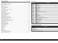
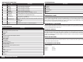
REPLACEMENT PARTS
Item # Description
HAN339001 Fuselage
HAN339002 Wing Set
HAN339003 Fin and Rudder
HAN339004 Stab and Elev Set
HAN339005 Retract Set
HAN339006 Retract Controller
HAN339007 Canopy Hatch
HAN339008 Canopy
HAN339009 Joiner Tube Set
HAN339010 Air Intakes (2)
HAN339011 Tip Tanks (2)
HAN339012 Tailpipe
HAN339013 Fuel Tank
HAN339014 Hardware Set
HAN339015 Retract Motor
HAN339016 Nose Wheel (65mm)
HAN339017 Main Wheel (65mm) with Brake (1)
HAN339018 Main Retracts / Struts (2)
HAN339019 Nose Retract with Strut
HAN339020 Fuselage Hatch; Upper
HAN339021 Fuselage Hatch; Lower
HAN339022 Main Tire Set (2)
HAN339023 Ventral Fin Set
HAN339024 Decal Sheet
REQUIRED ADHESIVES
Description
15-minute epoxy
30-minute epoxy
Canopy Glue
Thin CA
Medium CA
Threadlock, low and high strength

4EN
REMOVING WRINKLES
The covering of your model may develop wrinkles during shipping and will require the use of a heat gun (HAN100)
and covering glove (HAN150) or covering iron with a sealing iron sock (HAN141) to remove them. Use caution while
working around areas where the colors overlap to prevent separating the colors. Avoid using too much heat, which
could separate the colors. Placing a cool damp cloth on adjacent colors will also help in preventing the separation of
the colors while removing wrinkles.
BUILDING PRECAUTIONS
Prepare the work surface prior to beginning the build. The surface should be soft and free of any sharp objects. We
recommend resting the airframe parts on a soft towel or pit mat to prevent scratching or denting the surface of the
aircraft.
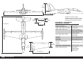
TRANSPORTATION AND STORAGE
Use the three-view drawing on page 90 to determine how much room will be required to transport and store your
model. We also recommend the use of wing and stabilizer bags to help protect these surfaces during transport and
storage. The control horns and linkages can cause damage to other surfaces even when placed in storage bags.
Always transport and store the wings and stabilizer so the linkages do not contact other panels to prevent damage.
CHECKING BLIND NUTS
When building the aircraft, you will be required to thread machine screws into blind nuts. We recommend pre-threading
the screws to make sure the blind nuts are clear of any debris. If the screws do not thread in easily, clear the threads
using the appropriate tap and tap handle.
REPLACEMENT COVERING
Your model is covered with UltraCote® fi lm in the following colors. If repairs are required, order these coverings to
make those repairs.
HANU870 White
HANU877 Orange
HANU873 Deep Blue
TOOLS REQUIRED
Description
Drill and tap set, metric
Drill bit set, Imperial or Metric
Epoxy brushes
Felt-tipped pen
Hemostats
Hex wrench set, Imperial and Metric
Hobby knife with #11 blade
Hook and loop straps
Hook and loop tape
Isopropyl alcohol
Low-tack tape
Mixing sticks
Needle nose pliers
Nut driver set, Imperial and Metric
Paper towels
Pencil
Petroleum jelly
Phillips screwdriver: #1, #2
Pin vise
Ruler
Sandpaper
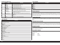
REQUIRED FOR COMPLETION
# Required Item # Description
1 DUB674 Super Strength Standard Servo Arms: JR
1 DUB675 Super Strength Standard Servo Arms: HRC
2 SPMA3002 Heavy-Duty Servo Extension 9-inch
1 SPMA3003 Heavy-Duty Servo Extension 12-inch
9 SPMA3004 Heavy-Duty Servo Extension 18-inch
3 SPMA3007 Heavy-Duty Servo Extension 48-inch
1 SPMAR14400T AR14400T 14 Channel PowerSafe Telemetry Receiver
4 SPMSA5080 A5080 MT/HS Mini Digital HV Servo (elevators, rudder and nose steering)
4 SPMSA6320 A6320 H-T/H-S Brushless HV Servo (ailerons and fl aps)
3SPMX20002SRX 7.4V 2000mAh 2S 15C Smart LiPo Receiver Battery: Universal Receiver,
IC3(Receiver x2 and Retracts x1)
1SPMX32003SLFRX 9.9V 3200mAh 3S 15C Smart LiFe ECU Battery: Universal Receiver, IC3
(Turbine)
1 60-85N Turbine
1 Air Trap
1 HAN116 Fuel Filler with “T” Fitting and Overfl ow Fitting
TOOLS REQUIRED
Description
Scissors
Side cutters
Square
Tap handle
Tie wraps
Toothpicks
Wire stripper

5 EN
Aermacchi MB-339 60–85N
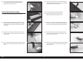
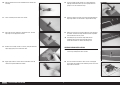
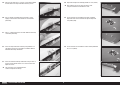
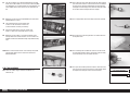
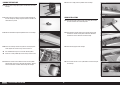
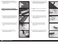
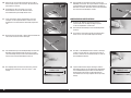
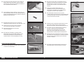
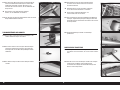
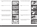
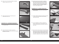
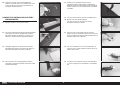
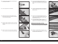
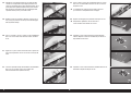
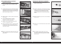
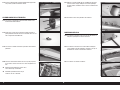
6. Remove the fl ap and hinges. Inject adhesive into each of the
hinge pockets of the fl ap.
Deluxe Materials Aero Tech Epoxy
(DLMAD64) is recommended.
7. Inject adhesive into each of the hinge pockets of the wing.
8. Apply a small amount of adhesive to each hinge where it will
enter the fl ap and wing.
9. Place the hinges in the fl ap, then join the fl ap to the wing.
Check the alignment as outlined in Step 5.
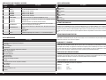
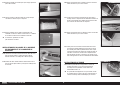
FLAP HINGING
1. Remove the fl ap and fl ap hinges from the wing panel.
The hinges are not glued to the wing or flap.
Optional: Apply a piece of white covering
for a more finished appearance.
2. Use a hobby knife and covering iron to seal the covering into
the recessed control horn mounting area on the leading edge
of the fl ap.
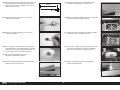
3. Check the hinges to make sure they operate freely. Adjust the
tension of the screw if any hinges do not move freely. Apply
a small amount of petroleum jelly to the hinge fl ex points to
prevent adhesive from entering the hinge.
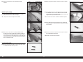
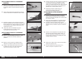
4. Check the fi t of the fl ap to the wing using the hinges. The
fl ap will align with the wing root. The hinge gap will be equal
along the length of the fl ap.
Do not apply any adhesives until instructed to do so.
5. Check the gaps between the aileron and fl ap, and the wing
root and fl ap. The fl ap will also align with the trailing edge at
the aileron and wing root. The fl ap and wing lower surfaces
will align.

6EN
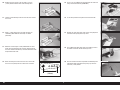
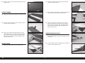
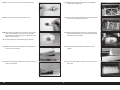
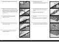
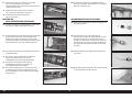
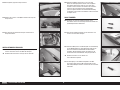
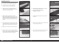
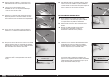
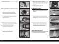
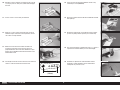
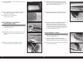
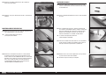
AILERON CONTROL HORN AND HINGING
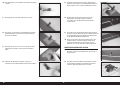
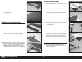
11. Remove the aileron and aileron hinges from the wing.
10. Use a paper towel and isopropyl alcohol to remove any
excess adhesive. Use low-tack tape to hold the fl ap in
position until the adhesive fully cures.
12. Lightly rub a fi nger over the bottom of the aileron to locate
the mounting slots for the aileron control horns. Use a hobby
knife and #11 blade to remove the covering for the aileron
control horns.
13. Lightly sand the area of the aileron control horns where they
fi t into the aileron. (The aileron control horns are the longest
horns included.)
14. Use a paper towel and isopropyl alcohol to remove any oils or
debris from the control horn. Prepare all four aileron control
horns.
15. Test fi t the aileron control horn. They should fi t completely
into the slot as shown. If they don’t fi t, use a fi le to enlarge
the slot. Do not force the horn into place.
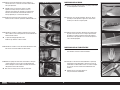
16. Snap the aluminum ball into the plastic ball end.
Apply a drop of light machine oil to the ball to
allow it to move freely in the plastic ball end.
17. Slide an M3 x 15 button head machine screw into the ball.
It may be necessary to use a small round fi le to remove any
burrs from inside the aluminum ball. Prepare two ball ends.
18. Slide an M3 washer on the M3 x 15 button head machine
screw. Pass the screws into one of the control horns, then
slide the ball end on the screw.
19. Slide the remaining control horn on the M3 x 15 button head
machine screw. Secure the assembly using an M3 washer
and an M3 locknut.

7 EN
Aermacchi MB-339 60–85N
20. Slide the control horn base on the bottom of the control horn
assembly.
21. Fit the assembly into the slots in the aileron.
22. Place low-tack tape around the control horn base. This will
help keep excess epoxy off the aileron.
23. Remove the assembly and mix 1/2 ounce (15ml) of 30-minute
epoxy. Apply epoxy in the control horn slots.
24. Apply epoxy to all the surfaces of the control horns that will
contact the exposed wood of the aileron.
25. Fit the assembly into the aileron. Use a paper towel and
isopropyl alcohol to remove any excess epoxy. Allow the
epoxy to cure, then remove the tape.
26. Hinge the ailerons using the same technique outlined for the
fl ap hinges. Make sure the aileron is aligned with the fl ap.
27. Make sure hinge gap is consistent along the entire length of
the aileron. Use low-tack tape to hold the aileron in position
until the adhesive has fully cured.
Trial fitting the tip tank at this stage allows for the
installation of the aileron and verification that the
aileron will not come in contact with the tip tank.
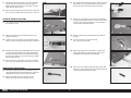
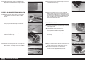
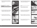
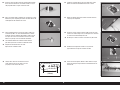
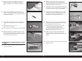
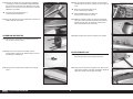
AILERON SERVO INSTALLATION
28. Remove the covering for the servo arm in the aileron servo
cover using a hobby knife and #11 blade.
29. Place the aileron servo on the cover and use a felt-tipped
pen to mark the locations for the mounting screws. The servo
output will face forward.

8EN
5/8 inch
(16mm)
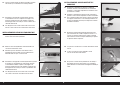
30. Remove the servo and use a pin vise with a 1/16-inch
(1.5mm) drill bit to drill the four servo mounting holes.
31. Thread a servo mounting screw into each hole, then remove
the screws.
32. Apply 1–2 drops of thin CA in each hole to harden the
surrounding wood. Allow the CA to fully cure before
proceeding.
33. Mount the servo using the screws provided with the servo.
Center the servo and attach the servo arm perpendicular to
the servo centerline. Remove any arms that will interfere with
the operation of the servo.
34. When connecting the clevis to the servo arm, use the hole
that is 5/8 inch (16mm) from the center of the servo arm.
35. Secure a 12-inch (300mm) servo extension to the servo lead
using a Servo Connector Clip (SPMA3054).
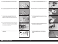
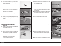
37. Remove the cover for the fl ap servo. Use the string to pull the
extension to the opening for the fl ap servo.
36. Tie the string inside the wing to the end of the extension.
38. Use a toothpick or hobby knife with a #11 blade to puncture
the aileron servo cover for the mounting screws.
39. Place the aileron servo cover in position and drill through the
mounting locations and into the wing using a pin vise and
3/64-inch (1.2mm) drill bit.

9 EN
Aermacchi MB-339 60–85N
40. Use a #1 Phillips screwdriver to thread an M2 x 8 self-tapping
screw into each of the holes. Remove the screws before
proceeding.
Do not apply too much force when installing these screws,
as it may damage the wooden servo hatch frame.
41. Apply 1–2 drops of thin CA in each hole to harden the
surrounding wood. Allow the CA to fully cure before
proceeding.
42. Secure the aileron servo cover using a #1 Phillips screwdriver
and four M2 x 8 self-tapping screws.
45. Attach the ball end to the control horn, then the clevis to the
servo arm. With the radio system on and the aileron servo
centered, adjust the linkage to center the aileron. Once
adjusted, slide the silicone retainer over the forks of the
clevis.
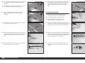
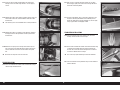
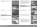
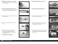
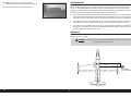
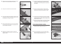
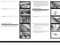
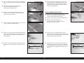
FLAP SERVO INSTALLATION
Before starting the flap servo installation, ensure the
Flap System travel is zero for all switch positions.
46. Snap the aluminum ball into the plastic ball end.
Apply a drop of light machine oil to the ball to
allow it to move freely in the plastic ball end.
48. Remove any tape from the wing and fl ap. Assemble the fl ap
linkage using two prepared ball ends and an 80mm threaded
rod. Thread the ball ends equally on the threaded rod until the
length is approximately 41/4 inches (108mm).
49. Center the fl ap servo using the radio system. Fit the fl ap
servo arm on the servo so it is perpendicular to the servo
centerline.
47. Slide an M3 x 15 button head machine screw into the ball. It
may be necessary to use a small round fi le to remove the any
burrs from inside the aluminum ball. Prepare four ball ends.
43. Slide a silicone retainer on the metal clevis. Thread the clevis
on the 70mm threaded rod (on the end with the nut) until the
end of the threaded rod is visible between the forks of the
clevis.
44. Remove the ball from the aileron control horn. Assemble the
linkage so the length is 33/4 inches (95mm).
33/4 inches (95mm)
41/4 inches (108mm)

10EN
5/8 inch
(16mm)
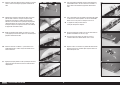
50. Place the fl ap servo into position with the output forward. Use
side cutters to remove the excess servo arm extending out of
the servo opening.
51. Attach the ball end to the servo arm using an M3 x 15
machine screw, M3 washer and M3 locknut. Tighten the
hardware using a 2mm hex wrench and 5.5mm nut driver.
Make sure not to overtighten the hardware.
The washers must be installed as shown to prevent
the ball from popping out of the ball end.
Trim any excess servo arm extending beyond the ball end.
When connecting the clevis to the servo arm, use the hole
that is 5/8 inch (16mm) from the center of the servo arm.
53. Guide the servo lead for the fl ap and aileron through the wing
to the wing root.
52. Install the fl ap servo with the output forward. Use the
hardware included with the servo.
54. Center the servo using the radio system. Place the servo arm
on the servo so it is one spline toward the trailing edge of the
wing.
Do not secure the servo arm to the
servo until instructed to do so.
55. Position the linkage so it is perpendicular to the fl ap hinge
line.
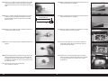
56. While holding the linkage, defl ect the fl ap. Use a felt-tipped
pen to mark the location of the ball end on the bottom of the
wing.
57. Use a felt-tipped pen to transfer the mark onto the fl ap and
into fl ap control horn mounting area.
58. Position the fl ap control horn on the fl at area of the fl ap,
centered with the mark made in the previous step. Slide the
fl ap control horn toward the bottom of the fl ap with the fl at
portion of the control horn facing the bottom of the wing.
Mark the location of the fl ap horn mounting screws using a
felt-tipped pen.

11 EN
Aermacchi MB-339 60–85N
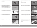
59. Place the horn aside. Use a 1/16-inch (1.5mm) drill bit to drill
the two holes for the fl ap control horn mounting screws.
60. Use a #1 Phillips screwdriver to thread an M3 x 14 self-
tapping screw into each hole. Remove the screws before
proceeding.
61. Place 2–3 drops of thin CA in each hole. Allow the CA to fully
cure before proceeding.
63. Secure the ball link to the fl ap control horn using an M3 x 15
machine screw and M3 washer. Use a 2mm hex wrench to
tighten the screw.
The servo horn can be removed from the
servo to manipulate the linkage.
64. Adjust the linkage for the mid fl ap position of 1 inch (25mm).
Once adjusted, secure the servo arm to the servo
using the hardware included with the servo.
65. Set the travel on the transmitter to the fl aps up position.
Adjust the values at the transmitter to align the fl ap to the
wing trailing edge.
62. Secure the fl ap control horn to the fl ap using two M3 x 14
self-tapping screws and a #1 Phillips screwdriver. Note the
orientation of the fl ap control horn.
66. Set the travel on the transmitter to achieve full fl ap defl ection
of 23/4 inch (70mm).

12EN
67. Attach the servo cover to the wing using four M2 x 8mm self-
tapping screws.
ELEVATOR HINGING
68. Separate the elevator from the stabilizer. Set the hinges aside.
69. Install the control horn for the elevator using the techniques
used for the aileron control horn.
70. Use the same technique as the fl ap hinges to secure the
elevator hinges. Make sure to remove any excess adhesive
from the hinges using a paper towel and isopropyl alcohol.
Use low-tack tape to hold the elevator in position until the
adhesive has fully cured.
RUDDER HINGING
71. Separate the rudder from the fi n. Set the hinges aside.
72. Install the control horn for the rudder using the techniques
used for the aileron control horn.
73. When installing the rudder hinges, note that the bottom hinge
has been shortened to fi t behind the fi n joiner tube.
74. Use the same technique as the fl ap hinges to secure the
rudder hinges. Make sure to remove any excess adhesive
from the hinges using a paper towel and isopropyl alcohol.
Use low-tack tape to hold the rudder in position until the
adhesive has fully cured.
RUDDER SERVO INSTALLATION
75. Mount the rudder servo following the instructions in the
aileron servo installation. The output of the rudder servo will
face forward.
76. Secure the rudder servo in the fi n following the instructions in
the aileron servo installation section.

13 EN
Aermacchi MB-339 60–85N
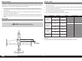
77. Assemble the rudder servo linkage. Use a 35mm threaded
rod and adjust the linkage to an overall length of 65mm.
Adjust the length of the linkage as necessary to center the
rudder with the radio system on.
When connecting the ball end to the servo arm, use the hole
that is 13/16 inch (20mm) from the center of the servo arm.
ELEVATOR SERVO INSTALLATION
78. Use a hobby knife and #11 blade to remove the covering for
the elevator servo arm.
79. Mount the elevator servo in the stabilizer with the servo
output facing forward.
Caution: Use care when locating the servo mounting holes
so they are evenly spaced from the notch for the servo lead.
80. Assemble the elevator servo linkage following the instructions
in the aileron servo installation. Use a 40mm threaded rod
and adjust the linkage to an overall length of 65mm. Adjust
the length of the linkage as necessary to center the elevator
with the radio system on.
When connecting the clevis to the servo arm, use the hole
that is 13/16 inch (20mm) from the center of the servo arm.
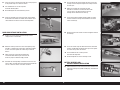
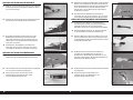
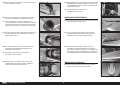
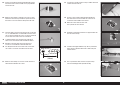
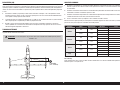
MAIN RETRACT INSTALLATION
81. Assemble an adapter to power the retract module. Use the
connector supplied with the retract module and a connector
compatible to the battery chosen to power the module.
Make sure to double check the polarity, as reverse
polarity will damage the retract unit beyond repair.
82. Use a hobby knife or sandpaper to sand a slight taper on each
of the plugs on the leads (included with the retract module)
that will connect to the receiver to the retract module.
83. Remove the covering from the retract well on the bottom of
the wing using a hobby knife with a #11 blade. Leave enough
covering to seal into the wheel well. Use a covering iron to
seal the covering around the opening.
84. Route the brake lead and control lead from the retract into
the wing.
The excess lead can be coiled and secured
with a zip tie in the wing root.
85. Retrieve the leads from the same location as the fl ap and
aileron leads. Make sure to label the leads so they can be
identifi ed when assembling the model for fl ight.
86. Prepare the retract mounting screws by sliding a 4mm lock
washer, then a 4mm washer on the M4 x 20 socket head cap
screws. Prepare all four mounting screws.

14EN
87. Secure the retract in the wing using the four screws prepared
in the previous step and a 3mm hex wrench.
Use threadlock on the screws to prevent
them from vibrating loose.
Do not overtighten the retract mounting screws.
88. Check the operation of the retract using the retract module.
A test button is located on the module, or the module can be
connected to the receiver to check the retract operation.
NOSE GEAR RETRACT INSTALLATION
89. Remove the canopy from the forward fuselage. Set the
canopy aside in a safe location.
90. Mount the steering servo in the retract servo opening using
four M3 x 12 button head screws. Apply a drop of threadlock
on each screw, then tighten the screws using a 2mm hex
wrench.
Some servos may require the orientation to be
reversed to avoid contacting the retract unit. To
do so may require a different length pushrod.
91. Assemble the steering linkage and attach it to the servo arm
using an M3 x 15 button head screw, M3 washer and M3 lock
nut. Use a 2mm hex wrench and 5.5mm nut driver.
92. Snap the ball on the steering arm of the retract. Center the
steering servo and adjust the length of the linkage to center
the nose gear.
Make sure to adjust the servo travel so equal
defection is achieved in each direction. Also make
sure the servo is not over traveling as this may
damage the ball attached to the nose leg.
93. Fit the retract into the forward fuselage. Make sure all the
leads are inside the fuselage and not between the retract
frame and fuselage.
94. Route the leads for the retract and servo on opposite sides of
the fuselage.
95. Secure the retract using four 4mm lock washers, four 4mm
washers and four M4 x 20 socket head cap screws. Tighten
the screws using a 3mm hex wrench.
Use threadlock on the screws to prevent
them from vibrating loose.
Do not overtighten the retract mounting screws.
BATTERY, RECEIVER AND
RETRACT MODULE INSTALLATION
96. Mount the batteries for the receiver and retract module in the
front of the fuselage using hook and loop tape, and hook and
loop straps.

15 EN
Aermacchi MB-339 60–85N
97. The retract module can be mounted forward of the aft edge
of the nose section. Make sure access to the connecting bolts
are not blocked. Use a switch between the retract battery and
retract module so the retract system can be switched on or
off.
99. Mount the receiver switch in a convenient location in the
fuselage. One of the remote receivers can be secured in the
forward section of the forward fuselage using hook and loop
tape.
100. Mount a second remote receiver in the fuselage using hook
and loop tape. Make sure the antennas are oriented in
different directions.
FUEL TANK ASSEMBLY
101. Locate the rubber stopper, aluminum backplate and
aluminum cap.
98. Mount the receiver in the fuselage following the instructions
provided with the receiver.
The leads between the retract module and
receiver can be connected, as well as the
receiver batteries and nose gear steering.
Connect the leads for the main gear retracts and
brakes, as well as the connections to the receiver.
102. Slide a long tube and a short tube through the rubber stopper.
(The center hole is for the screw that secures the assembly in
the tank.) Fit the aluminum backplate on the tubes from the
unfl anged end of the stopper. The aluminum front plate slides
on the tubes from the fl anged end of the stopper.
103. Use a tubing bender to bend the longer (vent) tube upwards.
104. Check the bend in the tubing to make sure it does not touch
the top of the tank.
105. Use a soldering iron and solder to create an area on each of
the tubes (both outside, and the unbent tube inside the tank)
so the fuel tubing can be secured to the tubes.
106. Cut a piece of fuel tubing and slide it on the clunk line for the
fuel tank. Fit the clunk and measure the length shown. Adjust
the length of the tubing to achieve the measurement. 101/2 inches (267mm)

16EN
107. Use a wire tie to secure the fuel line to the brass fuel line. 112. Mount the fuel tank tray in the fuselage from the bottom
using the four knurled screws.
113. Pass the three tie wraps around the fuel tank tray so the fuel
tank can be secured to the fuel tank tray.
114. Slide the fuel tank into the fuselage. Use a small amount of
silicone adhesive between the tray and tank to keep it from
sliding on the tray during fl ight.
115. Adjust the position of the tank so the top hatch can be
installed.
116. Secure the tank using the tie wraps. Trim the excess using
side cutters.
108. Use a wire tie to secure the fuel line to the clunk.
109. Fit the stopper in the tank and check that the clunk can move
freely in the tank. Adjust if necessary. Secure the stopper
using the M3 x 25 socket head cap screw. Tighten the screw
using a 2.5mm hex wrench.
Do not overtighten the screw and damage the fuel tank.
110. Remove the hatch from the bottom of the rear fuselage and
set it aside in a safe location.
111. Remove the hatch from the top of the rear fuselage and set it
aside in a safe location.

17 EN
Aermacchi MB-339 60–85N
117. Remove the covering for the fi ll and vent fi ttings using a
hobby knife and #11 blade. Mount the fi ttings and connect
the lines from the tank.
It may be necessary to enlarge the holes to install the fittings.
ELEVATOR AND RUDDER EXTENSION INSTALLATION
118. Locate the servo wire routing sleeve in the rear fuselage
in the fi n location. Tie the string to a 48 inch (1200mm)
extension.
119. Wrap tape around the connection between the plug and string
to make pulling the extension through the sleeve easier.
120. Use the string to pull the extension through the sleeve. Be
careful not to break the string.
121. Locate the servo routing sleeve in the rear fuselage in the
stabilizer location. Tie the string to two 48 inch (1200mm)
extensions. Make sure the plugs connect to the receiver.
122. Use the string to pull the extensions through the sleeve. Be
careful not to break the string.
123. Slide the servo routing sleeves as far back as possible.
Mark the sleeves at the bulkhead so the positioning can be
checked before each fl ying session. Use tie wraps to secure
the sleeves to the structure above the location for the thrust
tube, so they don’t come in contact with the exhaust tube
during the operation of your model.
TURBINE INSTALLATION
124. Fit the exhaust guard to the rear of the fuselage so it equally
covers the fuselage. Secure the guard using two M3 x 12
self-tapping screws.
Failure to fit the exhaust guard will result in
heat damage to the wood and covering above
the tailpipe at the rear of the fuselage.
125. Slide the exhaust tube into the rear fuselage from the front of
the fuselage.
126. Align the end of the exhaust tube so it extends 1/4 to 1/2 inch
(6mm to 13mm) beyond the fuselage former at the rear.
It may be necessary to slide a thin steel ruler (or
similar) between the exhaust tube and opening in the
fuselage to aid the tailpipe fitting through the end
fuselage former. This is designed to be a snug fit.

18EN
127. Space the exhaust tube equally between the sides of the
fuselage. Secure the tube using four M3 x 12 self-tapping
screws.
128. Position the turbine so the distance between the tail cone and
exhaust tube match the recommendations from the turbine
manufacturer.
The mounting rails can be modified to fit a variety of turbines.
130. Mount the fuel pump in the fuselage and connect any fuel
lines necessary for the operation of the turbine. Connect the
vent line from the tank. Secure all connections using wire
ties.
Do not use tie wraps to secure the fuel lines.
129. Position the turbine in accordance to the distance relative to
the tailpipe stated in the operations manual of your turbine
manufacturer.
FIN INSTALLATION
131. Secure the lead from the rudder servo and extension using a
commercially available retainer.
132. Mix 1/2 ounce (15ml) of 30-minute epoxy. Use an epoxy
brush to apply epoxy in the tubes in the fuselage for the fi n
and to the surrounding wood.
133. Fit the fi n into position. Place a small piece of plastic in the
hinge line and along the bottom of the rudder to prevent
gluing the rudder to the fuselage. Remove any excess epoxy
using a paper towel and isopropyl alcohol.
STABILIZER INSTALLATION
134. Insert the stabilizer tube in the socket in the rear of the
fuselage. Center the tube in the fuselage.
135. Connect the lead from the elevator servo and extension using
a commercially available fastener. Slide the stabilizer on
the tube. Use a 3mm hex wrench to tighten the screw that
secures the stabilizer to the fuselage.
The screw may require loosening to install the stabilizer.
136. Insert the stabilizer screw grommet using a small amount of
silicone adhesive.

19 EN
Aermacchi MB-339 60–85N
JOINING THE FUSELAGE
137. Slide the four fuselage joining tubes into the front half of the
fuselage.
138. Prepare the fi ve screws that secure the forward fuselage to
the rear fuselage by sliding a tapered washer on an M4 x 20
socket head cap screw.
140. Secure the fuselage section using the fi ve screws prepared
earlier. Tighten the screws using a 3mm hex wrench.
Use threadlock to keep the screws from vibrating loose.
Check the screws periodically to ensure they remain secure.
139. Slide the forward fuselage into position on the rear fuselage.
141. Mount the remote receiver above the fuel tank using hook
and loop tape. Connect any extensions for the fl aps, ailerons,
retracts and brakes and route them through the fuselage.
142. Place the canopy hatch in position on the fuselage.
WING INSTALLATION
143. Slide the wing tube into the socket in the wing. Do not force
the tube in farther than it will easily slide.
144. Slide the tube into the socket in the fuselage. Connect the
leads for the aileron and fl ap to the extensions. Guide the
leads for the retract and brake into the fuselage.
145. Slide the wing against the fuselage.
146. Use the two 1/4-20 x 2-inch nylon bolts to secure the wing to
the fuselage.

20EN
147. Connect the leads for the retract and brake inside the
fuselage.
151. Attach the tip tank using the screws and a 3mm hex wrench.
INTAKE INSTALLATION
148. Fit the intake to the wing. There will be space of 1/4-inch
(6mm) at the rear corner near the fuselage.
The top of the intake is longer than the bottom.
152. Use a hobby knife and #11 blade to remove the covering for
the VOR blade antenna in the fi n. Glue the antenna to the fi n
using medium CA. Use a square to make sure the antenna are
aligned correctly on both sides of the fi n.
The antenna are cosmetic and their installation is optional.
153. Slide a 4mm lock washer and 4mm washer on the M4 x 20
socket head cap screw for the ventral fi n attachment. Prepare
all four screws.
149. Use a pin vise and 1/16-inch (1.5mm) to drill to drill the
locations in the intake into the wing. Remove the intake and
thread an M2 x 8 self-tapping screw into each hole. Remove
the screws and place a drop of thin CA in each hole. Once the
CA has fully cured, secure the intake to the wing using twelve
M2 x 8 self-tapping screws.
154. Use the screws and a 3mm hex wrench to attach the ventral
fi ns to the bottom of the fuselage.
Remove the ventral fins for transport.
SCALE ACCESSORIES
150. Prepare the wing tip tank bolts by sliding a 4mm lock washer
on the M4 x 20 socket head cap screws.
La pagina si sta caricando...
La pagina si sta caricando...
La pagina si sta caricando...
La pagina si sta caricando...
La pagina si sta caricando...
La pagina si sta caricando...
La pagina si sta caricando...
La pagina si sta caricando...
La pagina si sta caricando...
La pagina si sta caricando...
La pagina si sta caricando...
La pagina si sta caricando...
La pagina si sta caricando...
La pagina si sta caricando...
La pagina si sta caricando...
La pagina si sta caricando...
La pagina si sta caricando...
La pagina si sta caricando...
La pagina si sta caricando...
La pagina si sta caricando...
La pagina si sta caricando...
La pagina si sta caricando...
La pagina si sta caricando...
La pagina si sta caricando...
La pagina si sta caricando...
La pagina si sta caricando...
La pagina si sta caricando...
La pagina si sta caricando...
La pagina si sta caricando...
La pagina si sta caricando...
La pagina si sta caricando...
La pagina si sta caricando...
La pagina si sta caricando...
La pagina si sta caricando...
La pagina si sta caricando...
La pagina si sta caricando...
La pagina si sta caricando...
La pagina si sta caricando...
La pagina si sta caricando...
La pagina si sta caricando...
La pagina si sta caricando...
La pagina si sta caricando...
La pagina si sta caricando...
La pagina si sta caricando...
La pagina si sta caricando...
La pagina si sta caricando...
La pagina si sta caricando...
La pagina si sta caricando...
La pagina si sta caricando...
La pagina si sta caricando...
La pagina si sta caricando...
La pagina si sta caricando...
La pagina si sta caricando...
La pagina si sta caricando...
La pagina si sta caricando...
La pagina si sta caricando...
La pagina si sta caricando...
La pagina si sta caricando...
La pagina si sta caricando...
La pagina si sta caricando...
La pagina si sta caricando...
La pagina si sta caricando...
La pagina si sta caricando...
La pagina si sta caricando...
La pagina si sta caricando...
La pagina si sta caricando...
La pagina si sta caricando...
La pagina si sta caricando...
La pagina si sta caricando...
La pagina si sta caricando...
La pagina si sta caricando...
La pagina si sta caricando...
La pagina si sta caricando...
La pagina si sta caricando...
La pagina si sta caricando...
La pagina si sta caricando...
-
 1
1
-
 2
2
-
 3
3
-
 4
4
-
 5
5
-
 6
6
-
 7
7
-
 8
8
-
 9
9
-
 10
10
-
 11
11
-
 12
12
-
 13
13
-
 14
14
-
 15
15
-
 16
16
-
 17
17
-
 18
18
-
 19
19
-
 20
20
-
 21
21
-
 22
22
-
 23
23
-
 24
24
-
 25
25
-
 26
26
-
 27
27
-
 28
28
-
 29
29
-
 30
30
-
 31
31
-
 32
32
-
 33
33
-
 34
34
-
 35
35
-
 36
36
-
 37
37
-
 38
38
-
 39
39
-
 40
40
-
 41
41
-
 42
42
-
 43
43
-
 44
44
-
 45
45
-
 46
46
-
 47
47
-
 48
48
-
 49
49
-
 50
50
-
 51
51
-
 52
52
-
 53
53
-
 54
54
-
 55
55
-
 56
56
-
 57
57
-
 58
58
-
 59
59
-
 60
60
-
 61
61
-
 62
62
-
 63
63
-
 64
64
-
 65
65
-
 66
66
-
 67
67
-
 68
68
-
 69
69
-
 70
70
-
 71
71
-
 72
72
-
 73
73
-
 74
74
-
 75
75
-
 76
76
-
 77
77
-
 78
78
-
 79
79
-
 80
80
-
 81
81
-
 82
82
-
 83
83
-
 84
84
-
 85
85
-
 86
86
-
 87
87
-
 88
88
-
 89
89
-
 90
90
-
 91
91
-
 92
92
-
 93
93
-
 94
94
-
 95
95
-
 96
96


Hangar 9 HAN3390 Manuale utente
- Categoria
- Giocattoli telecomandati
- Tipo
- Manuale utente
- Questo manuale è adatto anche per
in altre lingue
- English: Hangar 9 HAN3390 User manual
- français: Hangar 9 HAN3390 Manuel utilisateur
- Deutsch: Hangar 9 HAN3390 Benutzerhandbuch
Documenti correlati
-
 Hangar 9 HAN4670 Manuale del proprietario
-
 Hangar 9 HAN4720CR Manuale del proprietario
-
 Hangar 9 HAN5280 Manuale del proprietario
-
 Hangar 9 HAN2820 Manuale del proprietario
-
 Hangar 9 HAN5260 Manuale del proprietario
-
 Hangar 9 HAN2990 Manuale del proprietario
-
 Hangar 9 HAN2530 Manuale del proprietario
-
 Hangar 9 HANGAR 9 Ultra Stick 30cc Manuale del proprietario
-
 Hangar 9 HAN5260B Manuale del proprietario


