Panasonic WHSDC03H3E5 Istruzioni per l'uso
- Categoria
- Riscaldatori di spazio
- Tipo
- Istruzioni per l'uso
Questo manuale è adatto anche per

Nederlands Italiano Español English
Operating Instructions
Air-to-Water Heatpump
2-27
Thank you for purchasing Panasonic
product.
Before operating the system, read these operating
instructions thoroughly and keep them for future
reference.
Installation Instructions attached.
Instrucciones de funcionamiento
Bomba de calor Aire-Agua
28-53
Gracias por comprar un producto
Panasonic.
Antes de utilizar el sistema, sírvase leer
atentamente estas instrucciones de funcionamiento
y conservarlas como futuro elemento de consulta.
Instrucciones de instalación adjuntas.
Istruzioni operative
Pompa di calore Aria-acqua
54-79
Grazie per aver acquistato un prodotto
Panasonic.
Prima di utilizzare il sistema, si prega di leggere
attentamente le istruzioni operative e di conservare
questo opuscolo per potervi fare riferimento in
futuro.
Istruzioni per l’installazione allegate.
Gebruiksaanwijzing
Air-to-Water Warmtepomp
80-105
Hartelijk dank voor het aanschaffen van
een Panasonic-product.
Lees vóór u het systeem gebruikt deze
gebruiksaanwijzing grondig en bewaar deze voor
toekomstig gebruik.
De instructies voor installatie zijn bijgevoegd.
ACXF55-00070
Operating Instructions
Air-to-Water Heatpump
Model No.
Indoor Unit
WH-SDC03H3E5
WH-SDC05H3E5
Outdoor Unit
WH-UD03HE5
WH-UD05HE5

2
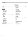
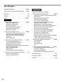
Table of contents
Safety precautions .........................................................4-6
Remote Controller buttons and display .........................7-9
Initialization .......................................................................9
Quick Menu ....................................................................10
Menus ........................................................................10-23
For user
Function setup ........................................................10-11
Weekly timer
Holiday timer
Quiet timer
Room heater
Tank heater
Sterilization
System check .........................................................11-12
Energy monitor
Water temperatures
Error history
Compressor
Heater
Personal setup .......................................................12-13
Touch sound
LCD contrast
Backlight
Backlight intensity
Clock format
Date & Time
Language
Unlock password
Service contact ............................................................13
Contact 1 / Contact 2
For installer
Installer setup
System setup ...........................................................14-18
Optional PCB connectivity
Zone & Sensor
Heater capacity
Anti freezing
Tank connection
Buffer tank connection
Tank heater
Base pan heater
Alternative outdoor sensor
Bivalent connection
External SW
Solar connection
External error signal
Demand control
SG ready
External compressor SW
Circulation liquid
Heat-Cool SW
Operation setup ......................................................18-22
Heat
Cool
Auto
Tank
Service setup ...........................................................22-23
Pump maximum speed
Pump down
Dry concrete
Service contact
Cleaning instructions ......................................................24
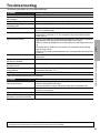
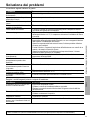
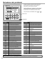
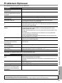
Troubleshooting .........................................................25-26
Information ......................................................................27

English
3
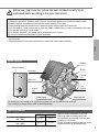
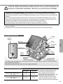
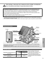
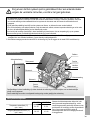
Outdoor
Unit
Power Supply
Solar Panel
Radiator
Shower
Fan Coil
Unit
Floor
Heating
Water Tank Unit
Indoor Unit
Remote Controller
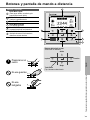
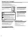
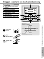
The illustrations in this manual are for explanation purposes only and may differ from the actual unit.
They are subject to change without notice for future improvement.
Operating conditions
HEATING *
1
COOLING
Water outlet temperature (°C)
(Min. / Max.)
20 / 55 5 / 20
Outdoor ambient temperature (°C)
(Min. / Max.)
-20 / 35 16 / 43
When the outdoor temperature is out of the
range in the table, the heating capacity will
drop signifi cantly and the outdoor unit may stop
operating for its protection.
The unit will restart automatically after the outdoor
temperature returns to the specifi ed range.
System overview
Before use, make sure the system has been installed correctly by an
authorised dealer according to the given instructions.
• Panasonic Air-to-Water Heatpump is a split system, consisting of two units: indoor and outdoor units. This system
is designed to operate with Panasonic Water Tank Unit. Unless used together with the Panasonic Water Tank Unit,
Panasonic does not guarantee any normal operation nor the reliability of the system.
• These operating instructions describe how to operate the system using the indoor and outdoor units.
• As for the operation of other products such as water tank, radiator, external thermo controller, and underfl oor units, refer
to the operating instructions of each product.
• Some functions described in this manual may not be applicable to your system.
• Consult your nearest authorised dealer for further information.
*1 The system is locked to operate without COOL mode. It can be unlocked only by authorised installers or our authorised
service partners.
*2 Only displayed when COOL mode is unlocked (This means when COOL mode is available)

4
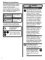
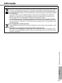
To prevent personal injury, injury to
others or property damage, please
comply with the following:
Incorrect operation due to failure to
follow instructions below may cause
harm or damage, the seriousness of
which is classifi ed as below:
WARNING
This sign warns of
death or serious
injury.
CAUTION
This sign warns of
injury or damage
to property.
The instructions to be followed are
classifi ed by the following symbols:
This symbol denotes
an action that is
PROHIBITED.
These symbols denote
actions COMPULSORY.
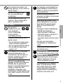
WARNING
Indoor unit and outdoor unit
This appliance may be used by
children aged from 8 years and
above and persons with reduced
physical, sensory or mental
capabilities or lack of experience
and knowledge if they have been
given supervision or instruction
concerning use of the appliance
in a safe way and understand
the hazards involved. Children
shall not play with the appliance.
Cleaning and user maintenance
shall not be made by children
without supervision.
Please consult an authorised
dealer or specialist to clean the
internal parts, repair, install,
remove and reinstall the unit.
Improper installation and
handling will cause leakage,
electric shock or fi re.
Confi rm with an authorised
dealer or specialist on usage of
any specifi ed refrigerant type.
Using refrigerant type other than
the specifi ed may cause product
damage, burst and injury etc.
Do not install the unit in
a potentially explosive or
fl ammable atmosphere. Failure
to do so could result in fi re.
Do not insert your fi ngers
or other objects into the
indoor or outdoor unit; the
rotating parts may cause
injury.
Safety precautions

English
5
Do not touch the outdoor unit
during lightning, it may cause an
electric shock.
Do not sit or step on the
unit, you may fall down
accidentally.
Do not install the indoor unit
outdoors. This is designed for
indoor installation only.
Power supply
Do not use a
modifi ed cord, joint
cord, extension
cord or unspecifi ed
cord to prevent
overheating and fi re.
To prevent overheating, fi re or
electric shock:
• Do not share the same power
outlet with other equipment.
• Do not operate with wet hands.
• Do not bend or twist power
supply cord.
If the supply cord is damaged,
it must be replaced by the
manufacturer, service agent or
similarly qualifi ed persons in
order to avoid a hazard.
This unit is equipped with
Residue Current Circuit Breaker
(RCCB). Ask an authorised
dealer to check RCCB operation
regularly, especially after
installation, inspection, and
maintenance. RCCB malfunction
may result in electric shock and/
or fi re.
It is strongly recommended that
Install Residual Current Device
(RCD) on-site to prevent electric
shock and/or fi re.
Before obtaining access to
terminals, all supply circuits must
be disconnected.
Stop using the product if any
abnormality/failure occurs and
disconnect the power supply.
(Risk of smoke/fi re/electric
shock)
Examples of abnormality/failure
• RCCB trips frequently.
• Burning smell is observed.
• Abnormal noise or vibration of
the unit is observed.
• Hot water leaks from the indoor
unit.
Contact your local dealer
immediately for maintenance/
repair.
Wear gloves during inspection
and maintenance.
This equipment must be earthed
to prevent electrical shock or fi re.
Prevent electric shock by
disconnecting the power supply
- Before cleaning or servicing.
- When extended non-use.
This appliance is for multiple
uses. To avoid electric shock,
burn and/or fatal injury, make
sure to disconnect all power
supplies before accessing any
terminal in the indoor unit.
Safety precautions

6
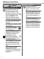
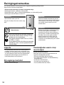
CAUTION
Indoor unit and outdoor unit
Do not wash the indoor unit
with water, benzine, thinner
or scouring powder to avoid
damage or corrosion on the unit.
Do not install the unit close
to any combustibles or in a
bathroom. Otherwise, it may
cause electric shock and/or fi re.
Do not touch the water discharge
pipe of the indoor unit during
operation.
Do not place any material on the
unit or under it.
Do not touch the sharp
aluminium fi n; sharp parts
may cause injury.
Do not use the system during
sterilization in order to prevent
scalding with hot water, or
overheating of shower.
Prevent water leakage by
ensuring that the drainage pipe
is connected properly.
After a long period of use, make
sure the installation rack is not
deteriorated. The deteriorated
rack may cause the unit to fall
down.
Ask an authorised dealer
to determine the level of
sterilization function fi eld settings
according to the local laws and
regulations.
Remote Controller
Do not wet the Remote
Controller. Failure to do so may
result in electric shock and/or
fi re.
Do not press the buttons on the
Remote Controller using hard
and sharp objects. Failure to do
so may cause damage to the
unit.
Do not wash the Remote
Controller using water, benzine,
thinner or scouring powder.
Do not inspect or maintain the
Remote Controller by yourself.
Consult an authorised dealer in
order to prevent personal injury
caused by incorrect operation.
Safety precautions

English
7
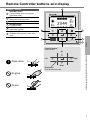
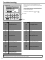
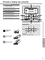
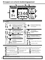
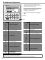
Remote Controller buttons and display
Buttons / Indicator
1
Quick Menu button
(For more details, refer to the separate
Quick Menu Guide.)
2
Back button
Returns to the previous screen
3 LCD Display
4
Main Menu button
For function setup
5
ON/OFF button
Starts/Stops operation
6
Operation indicator
Illuminates during operation, blinks during
alarm.
Press centre
No glove
No pen
2
1
4
5
6
3
Cross key buttons
Selects an item.
Enter button
Fixes the selected content.
Up
Down
Left Right
Safety precautions / Remote Controller buttons and display

8
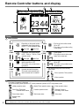
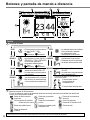
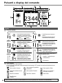
Remote Controller buttons and display
Display
1 Mode selection
AUTO
• Depending on the preset outdoor
temperature, the system selects
HEAT or *
1
COOL operation mode.
Auto Heat Auto Cool
*
1,
*
2
COOL • The fan coil unit is either turned
ON or OFF.
• The outdoor unit provides cooling
to the system.
AUTO
+ TANK
• Depending on the preset outdoor
temperature, the system selects
HEAT + TANK or *
1
COOL + TANK
operation mode.
Auto Heat Auto Cool
*
1,
*
2
COOL
+ TANK
• The outdoor unit provides cooling
to the system.
• The system controls the booster
heater in the water tank.
HEAT
• The panel/fl oor HEAT operation is
either turned ON or OFF.
• The outdoor unit provides heat to
the system.
TANK • The water tank is either turned
ON or OFF.
• The outdoor unit provides heat to
the water tank.
HEAT
+ TANK
• The outdoor unit provides heat to
the water tank and the system.
• This mode can be selected only
when the water tank is installed.
* The direction icons point to the currently
active mode.
• Room operation / Tank operation.
• Deice operation.
2
Operation icons
The status of operation is displayed.
Icon will not display (under operation OFF screen) whenever operation is OFF except weekly timer.
Holiday operation status Weekly Timer operation status Quiet operation status
Zone: Room Thermostat
→Internal sensor status
Powerful operation status
Demand Control or
SG ready or SHP status
Room Heater status Tank Heater status Solar status
Bivalent status
(Boiler)
*1 The system is locked to operate without COOL mode. It can be unlocked only by authorised installers or our authorised service partners.
*2 Only displayed when COOL mode is unlocked (This means when COOL mode is available).
2 43
1
5
6
7

English
9
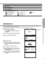
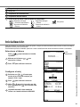
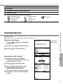
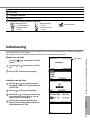
Initialization
Before starting to install the various menu settings, please initiate the Remote Controller by selecting the language of
operation and installing the date and time correctly.
It is recommended that the installer conducts the following initialization of the Remote Controller.
Selecting the language
LCD blinking
Press and wait while the display is
initializing.
1
Scroll with
and to select the language.
2
Press
to confi rm the selection.
Setting the clock
1
Select with
or how to display the time,
either 24h or am/pm format (for example, 15:00
or 3 pm).
2
Press
to confi rm the selection.
3
Use
and to select year, month, day,
hour and minutes. (Press to confi rm the
selection each time.)
4
Once the time is set, time and day will appear
on the display even if the Remote Controller is
turned OFF.
3 Temperature of each zone
4 Time and day
5 Water Tank temperature
6 Outdoor temperature
7 Sensor type/Set temperature type icons
Water Temperature
→Compensation curve
Water Temperature
→Direct
Pool only
Room Thermostat
→External
Room Thermostat
→Internal
Remote Controller buttons and display / Initialization

10
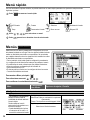
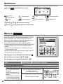
Menus
For user
Select menus and determine settings according to the system
available in the household. All initial settings must be done by an
authorised dealer or a specialist. It is recommended that all alterations
of the initial settings are also done by an authorised dealer or a
specialist.
• After initial installation, you may manually adjust the settings.
• The initial setting remains active until the user changes it.
• The Remote Controller can be used for multiple installations.
• Ensure the operation indicator is OFF before setting.
• The system may not work properly if set wrongly.
Please consult an authorised dealer.
To display <Main Menu>:
To select menu:
To confi rm the selected content:
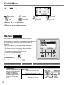
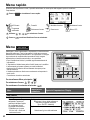
After the initial settings have been completed, you can select a quick menu from the following options and edit the setting.
1
Press
to display the quick menu.
Force DHW Powerful Quiet Force Heater
Timer Force Defrost Error Reset R/C Lock
2
Use
to select menu.
3
Press
to turn on/off the select menu.
Quick Menu
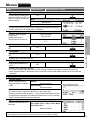
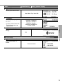
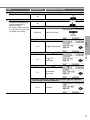
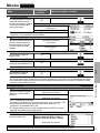
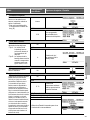
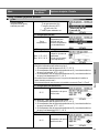
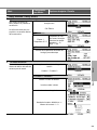
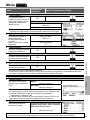
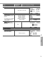
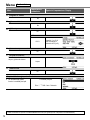
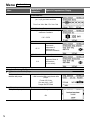
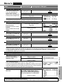
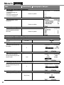
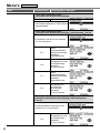
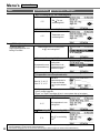
Menu Default Setting Setting Options / Display
Function setup
1
Weekly timer
Once the weekly timer is set up,
User can edit from Quick Menu.
To set up to 6 patterns of
operation on a weekly basis.
• Disabled if Heat-Cool SW is
pressed or if Force Heater
is on.
Timer setup
Select day of the week and
set the patterns needed
(Time / Operation ON/OFF / Mode)
Timer copy
Select day of the week

English
11
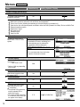
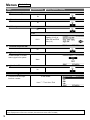
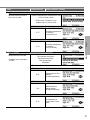
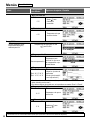
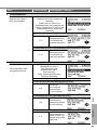
Menu Default Setting Setting Options / Display
2
Holiday timer
To save energy, a holiday period
may be set to either turn OFF the
system or lower the temperature
during the period.
OFF
ON
Holiday start and end.
Date and time
OFF or lowered temperature
• Weekly timer setting may be temporarily disabled during Holiday timer setting but
it will be restored once the Holiday timer is completed.
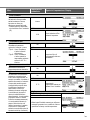
3
Quiet timer
To operate quietly during the
preset period.
6 patterns may be set.
Level 0 means the mode is off.
Time to start Quiet :
Date and time
Level of quietness:
0 ~ 3
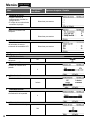
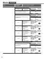
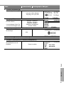
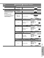
4
Room heater
To set the room heater ON or
OFF.
OFF
5
Tank heater
To set the tank heater ON or
OFF.
OFF
• Available only if connected to the tank.
6
Sterilization
To set the auto sterilization ON
or OFF.
OFF
• Available only if connected to the tank.
• Do not use the system during sterilization in order to prevent scalding with hot water, or overheating of shower.
• Ask an authorised dealer to determine the level of sterilization function fi eld settings according to the local laws and
regulations.
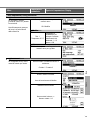
System check
1
Energy monitor
Present or historical chart of
energy consumption, generation
or COP.
Present
Select and retrieve
Historical chart
Select and retrieve
• COP= Coeffi cient of Performance.
• For historical chart, the period is selected from 1 day/1 week/1year.
• Energy consumption (kWh) of heating, *
1
cooling, tank and total may be retrieved.
• The total power consumption is an estimated value based on AC 230 V and may
differ from value measured by precise equipment.
2
Water temperatures
Shows all water temperatures in
each area.
Actual water temperature of 8 items:
Inlet / Outlet / Zone 1 / Zone 2 / Tank / Buffer
tank / Solar / Pool
Select and retrieve
Menus
For user
Quick Menu / Menus
*1 The system is locked to operate without COOL mode. It can be unlocked only by authorised installers or our authorised service partners.
*2 Only displayed when COOL mode is unlocked (This means when COOL mode is available).

12
Menus
For user
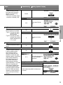
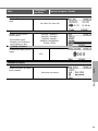
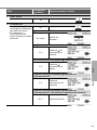
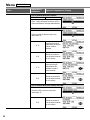
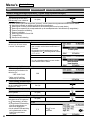
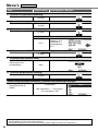
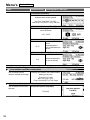
Menu Default Setting Setting Options / Display
3
Error history
• Refer to Troubleshooting for
error codes.
• The most recent error code is
displayed at the top.
Select and retrieve
4
Compressor
Shows the compressor
performance.
Select and retrieve
5
Heater
Total hours of ON time for Room
heater/Tank heater.
Select and retrieve
Personal setup
1
Touch sound
Turns the operation sound ON/
OFF.
ON
2
LCD contrast
Sets the screen contrast.
3
3
Backlight
Sets the duration of screen
backlight.
1 min
4
Backlight intensity
Sets screen backlight brightness.
4
5
Clock format
Sets the type of clock display.
24h

English
13
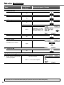
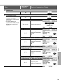
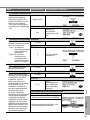
Menu Default Setting Setting Options / Display
6
Date & Time
Sets the present date and time.
Year / Month / Day / Hour / Min
7
Language
Sets the display language for the
top screen.
• For Dutch, Greek, Finnish and
Turkish, please refer to the
English version.
ENGLISH / FRANÇAIS /
DEUTSCH / ITALIANO /
ESPAÑOL / DANISH /
SWEDISH / NORWEGIAN /
POLISH / CZECH
8
Unlock password
4 digit password for all the
settings.
0000
Service contact
1
Contact 1 / Contact 2
Preset contact number for
installer.
Select and retrieve
Menus

14
Menus
For installer
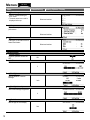
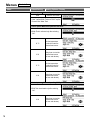
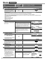
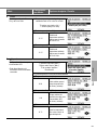
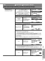
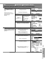
Menu Default Setting Setting Options / Display
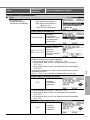
Installer setup System setup
1
Optional PCB connectivity
To connect to the external PCB
required for servicing.
No
• If the external PCB is connected (optional), the system will have following additional functions:
1
Buffer tank connection and control over its function and temperature.
2
Control over 2 zones (including the swimming pool and the function to heat water in it).
3
Solar function (the solar thermal panels connected to either the DHW (Domestic Hot Water) Tank or the Buffer Tank.
4
External compressor switch.
5
External error signal.
6
SG ready control.
7
Demand control.
8
Heat-Cool SW
2
Zone & Sensor
To select the sensors and to
select either 1 zone or 2 zone
system.
Zone
• After selecting 1 or 2 zone system, proceed to
the selection of room or swimming pool.
• If the swimming pool is selected, the
temperature must be selected for
T temperature between 2 °C ~10 °C.
Sensor
* For room thermostat, there is a further
selection of external or internal.
3
Heater capacity
To reduce the heater power if
unnecessary.*
3 kW / 6 kW / 9 kW
3 kW
* Options of kW vary depending
on the model.
4
Anti freezing
To activate or deactivate the
water freeze prevention when
the system is OFF
Yes
5
Tank connection
To connect tank to the system.
No
6
Buffer tank connection
To connect tank to the system
and if selected YES, to set
T temperature.
• The optional PCB connectivity
must be selected YES to
enable the function.
• If the optional PCB connectivity
is not selected, the function will
not appear on the display.
No
Yes
5 °C Set
T for Buffer Tank

English
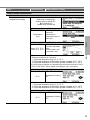
15
Menu Default Setting Setting Options / Display
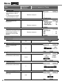
7
Tank heater
To select external or internal
tank heater and if External is
selected, set a timer for the
heater to come on.
* This option is available if Tank
connection is selected (YES).
Internal
External
0:20
Tank heater ON time
set.
8
Base pan heater
To select whether or not optional
base pan heater is connected.
* Type A - The base pan heater
activates only during
deice operation.
* Type B -The base pan heater
activates when outdoor
ambient temperature is
5 °C or lower.
No
Yes
A
Set base pan heater
type*.
9
Alternative outdoor sensor
To select an alternative outdoor
sensor.
No
10
Bivalent connection
To select a bivalent connection
to allow an additional heat
source such as a boiler to
heat-up the buffer tank and
domestic hot water tank when
heatpump capacity is insuffi cient
at low outdoor temperature.
The bivalent feature can be
set-up either in alternative
mode (heatpump and boiler
operate alternately), or in parallel
mode (both heatpump and
boiler operate simultaneously),
or in advance parallel mode
(heatpump operates and boiler
turns on for buffer-tank and/or
domestic hot water depending
on the control pattern setting
options).
No
Yes
-5 °C
Set outdoor temperature
for turn ON Bivalent
connection.
Yes After selecting the outdoor temperature
Control pattern
Alternative / Parallel / Advanced parallel
• Select advanced parallel for bivalent use of
the tanks.
Menus

16
Menu Default Setting Setting Options / Display
Control pattern Advanced parallel
Heat Selection of the tank
• “Heat” implies Buffer Tank and “DHW” implies
Domestic Hot Water Tank.
Control pattern
Advanced parallel Heat Yes
• Buffer Tank is activated only after selecting
“Yes”.
-8 °C
Set the temperature
threshold to start the
bivalent heat source.
0:30
Delay timer to start the
bivalent heat source
(in hour and minutes).
-2 °C
Set the temperature
threshold to stop the
bivalent heat source.
0:30
Delay timer to stop the
bivalent heat source
(in hour and minutes).
Control pattern Advanced parallel DHW Yes
• DHW Tank is activated only after selecting
“Yes”.
0:30
Delay timer to start the
bivalent heat source
(in hour and minutes).
Menus
For installer

English
17
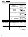
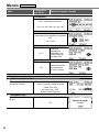
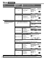
Menu Default Setting Setting Options / Display
11
External SW
No
12
Solar connection
• The optional PCB connectivity
must be selected YES to
enable the function.
• If the optional PCB connectivity
is not selected, the function will
not appear on the display.
No
Yes
Buffer tank Selection of the tank
Yes After selecting the tank
10 °C Set
T ON temperature
Yes After selecting the tank T ON temperature
5 °C
Set
T OFF
temperature
Yes After selecting the tank T ON temperature T OFF temperature
5 °C
Set Antifreeze
temperature
Yes After selecting the tank T ON temperature T OFF temperature
After setting the antifreeze temperature
80 °C Set Hi limit
Menus

18
Menu Default Setting Setting Options / Display
13
External error signal
No
14
Demand control
No
15
SG ready
No
Yes
120 %
Capacity (1) & (2) of
Buffer Tank and DHW
Tank (in %)
16
External compressor SW
No
17
Circulation liquid
To select whether to circulate
water or glycol in the system.
Water
18
Heat-Cool SW
No
Installer setup Operation setup
1
To access to the four major
functions or modes.
4 main modes
Heat / *
1,
*
2
Cool / Auto / Tank
Menus
For installer
*1 The system is locked to operate without COOL mode. It can be unlocked only by authorised installers or our authorised service partners.
*2 Only displayed when COOL mode is unlocked (This means when COOL mode is available).

English
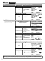
19
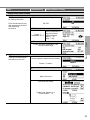
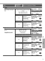
Menu Default Setting Setting Options / Display
Installer setup Operation setup
2
Heat
To set various water & ambient
temperatures for heating.
Water temp. for heating ON /
Outdoor temp. for heating OFF /
T for heating ON /
Outdoor temp. for heater ON
Water temp. for heating ON
Compensation
curve
Heating ON
temperatures in
compensation curve or
direct input.
Water temp. for heating ON Compensation curve
X axis: -5 °C, 15 °C
Y axis: 55 °C, 35 °C
Input the 4 temperature
points
(2 on horizontal X axis,
2 on vertical Y axis).
• Temperature range: X axis: -15 °C ~ 15 °C, Y axis: See below
• Temperature range for the Y axis input:
1. If High water temperature is NO: 20 °C ~ 55 °C
2. If High water temperature is YES & Back up heater is enabled: 25 °C ~ 65 °C
3. If High water temperature is YES & Back up heater is disabled: 35 °C ~ 65 °C
• If 2 zone system is selected, the 4 temperature points must also be input for Zone 2.
• “Zone 1” and “Zone 2” will not appear on the display if only 1 zone system.
Water temp. for heating ON Direct
35 °C
Temperature for heating
ON
• Min. ~ Max. range is conditional as follows:
1. If High water temperature is NO: 20 °C ~ 55 °C
2. If High water temperature is YES & Back up heater is enabled: 25 °C ~ 65 °C
3. If High water temperature is YES & Back up heater is disabled: 35 °C ~ 65 °C
Outdoor temp. for heating OFF
24 °C
Temperature for heating
OFF
Menus

20
Menu Default Setting Setting Options / Display
T for heating ON
5 °C
Set T for heating
ON.
Outdoor temp. for heater ON
0 °C
Temperature for
heater ON
3
*
1,
*
2
Cool
To set various water & ambient
temperatures for cooling.
Water temperatures for cooling ON
and
T for cooling ON.
Water temp. for cooling ON
Compensation curve
Cooling ON
temperatures in
compensation curve or
direct input.
Water temp. for cooling ON Compensation curve
X axis: 20 °C, 30 °C
Y axis: 15 °C, 10 °C
Input the 4 temperature
points
(2 on horizontal X axis,
2 on vertical Y axis)
• If 2 zone system is selected, the 4 temperature points must also be input for Zone 2.
• “Zone 1” and “Zone 2” will not appear on the display if only 1 zone system.
Water temp. for cooling ON Direct
10 °C
Set temperature for
Cooling ON
T for cooling ON
5 °C Set
T for cooling ON
Menus
For installer
*1 The system is locked to operate without COOL mode. It can be unlocked only by authorised installers or our authorised service partners.
*2 Only displayed when COOL mode is unlocked (This means when COOL mode is available).
La pagina si sta caricando...
La pagina si sta caricando...
La pagina si sta caricando...
La pagina si sta caricando...
La pagina si sta caricando...
La pagina si sta caricando...
La pagina si sta caricando...
La pagina si sta caricando...
La pagina si sta caricando...
La pagina si sta caricando...
La pagina si sta caricando...
La pagina si sta caricando...
La pagina si sta caricando...
La pagina si sta caricando...
La pagina si sta caricando...
La pagina si sta caricando...
La pagina si sta caricando...
La pagina si sta caricando...
La pagina si sta caricando...
La pagina si sta caricando...
La pagina si sta caricando...
La pagina si sta caricando...
La pagina si sta caricando...
La pagina si sta caricando...
La pagina si sta caricando...
La pagina si sta caricando...
La pagina si sta caricando...
La pagina si sta caricando...
La pagina si sta caricando...
La pagina si sta caricando...
La pagina si sta caricando...
La pagina si sta caricando...
La pagina si sta caricando...
La pagina si sta caricando...
La pagina si sta caricando...
La pagina si sta caricando...
La pagina si sta caricando...
La pagina si sta caricando...
La pagina si sta caricando...
La pagina si sta caricando...
La pagina si sta caricando...
La pagina si sta caricando...
La pagina si sta caricando...
La pagina si sta caricando...
La pagina si sta caricando...
La pagina si sta caricando...
La pagina si sta caricando...
La pagina si sta caricando...
La pagina si sta caricando...
La pagina si sta caricando...
La pagina si sta caricando...
La pagina si sta caricando...
La pagina si sta caricando...
La pagina si sta caricando...
La pagina si sta caricando...
La pagina si sta caricando...
La pagina si sta caricando...
La pagina si sta caricando...
La pagina si sta caricando...
La pagina si sta caricando...
La pagina si sta caricando...
La pagina si sta caricando...
La pagina si sta caricando...
La pagina si sta caricando...
La pagina si sta caricando...
La pagina si sta caricando...
La pagina si sta caricando...
La pagina si sta caricando...
La pagina si sta caricando...
La pagina si sta caricando...
La pagina si sta caricando...
La pagina si sta caricando...
La pagina si sta caricando...
La pagina si sta caricando...
La pagina si sta caricando...
La pagina si sta caricando...
La pagina si sta caricando...
La pagina si sta caricando...
La pagina si sta caricando...
La pagina si sta caricando...
La pagina si sta caricando...
La pagina si sta caricando...
La pagina si sta caricando...
La pagina si sta caricando...
La pagina si sta caricando...
La pagina si sta caricando...
La pagina si sta caricando...
La pagina si sta caricando...
-
 1
1
-
 2
2
-
 3
3
-
 4
4
-
 5
5
-
 6
6
-
 7
7
-
 8
8
-
 9
9
-
 10
10
-
 11
11
-
 12
12
-
 13
13
-
 14
14
-
 15
15
-
 16
16
-
 17
17
-
 18
18
-
 19
19
-
 20
20
-
 21
21
-
 22
22
-
 23
23
-
 24
24
-
 25
25
-
 26
26
-
 27
27
-
 28
28
-
 29
29
-
 30
30
-
 31
31
-
 32
32
-
 33
33
-
 34
34
-
 35
35
-
 36
36
-
 37
37
-
 38
38
-
 39
39
-
 40
40
-
 41
41
-
 42
42
-
 43
43
-
 44
44
-
 45
45
-
 46
46
-
 47
47
-
 48
48
-
 49
49
-
 50
50
-
 51
51
-
 52
52
-
 53
53
-
 54
54
-
 55
55
-
 56
56
-
 57
57
-
 58
58
-
 59
59
-
 60
60
-
 61
61
-
 62
62
-
 63
63
-
 64
64
-
 65
65
-
 66
66
-
 67
67
-
 68
68
-
 69
69
-
 70
70
-
 71
71
-
 72
72
-
 73
73
-
 74
74
-
 75
75
-
 76
76
-
 77
77
-
 78
78
-
 79
79
-
 80
80
-
 81
81
-
 82
82
-
 83
83
-
 84
84
-
 85
85
-
 86
86
-
 87
87
-
 88
88
-
 89
89
-
 90
90
-
 91
91
-
 92
92
-
 93
93
-
 94
94
-
 95
95
-
 96
96
-
 97
97
-
 98
98
-
 99
99
-
 100
100
-
 101
101
-
 102
102
-
 103
103
-
 104
104
-
 105
105
-
 106
106
-
 107
107
-
 108
108


Panasonic WHSDC03H3E5 Istruzioni per l'uso
- Categoria
- Riscaldatori di spazio
- Tipo
- Istruzioni per l'uso
- Questo manuale è adatto anche per
in altre lingue
- español: Panasonic WHSDC03H3E5 Instrucciones de operación
- Nederlands: Panasonic WHSDC03H3E5 Handleiding
Documenti correlati
-
Panasonic WHUD09HE5 Istruzioni per l'uso
-
Panasonic WHSXC12H9E8 Istruzioni per l'uso
-
-
-
-
-
-
-
-
Altri documenti
-
Tesy AquaThermica Eco 260 S Manuale utente
-
-
Duratech HS40 Guida utente
-
-
Duratech HS35 Manuale utente
-
Tesy AquaThermica Compact 100 Manuale utente
-
Tesy 206963 Manuale utente
-
 Kaysun High Temperature Hydraulic Module Manuale utente
-
Duratech Sun Spring Manuale utente
-
Hitachi PC-ARFHE Manuale utente
