Philips FR 740 & FR740 Manuale del proprietario
- Categoria
- Radio
- Tipo
- Manuale del proprietario

Surround sound receiver
FR740
FR760
MX740
La pagina si sta caricando...

3
English ....................................................4
Français.................................................24
Español .................................................44
Deutsch.................................................64
Nederlands ...........................................84
EnglishFrançaisEspañolDeutschNederlands
Italiano
Italiano................................................104

GENERAL INFORMATION
4
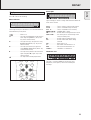
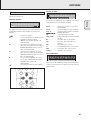
This receiver is supplied including:
– a remote control
– 2 batteries for the remote control, size AA
– a system bus cable for the CINEMA LINK connection
– a loop antenna
– a wire antenna
– 5 loudspeakers including 5 speaker cables (MX 740 only)
– a quick installation card (MX 740 only)
– this instruction booklet
Clean the receiver with a soft,
slightly dampened, lint-free cloth.
Do not use any cleaning agents as
they may have a corrosive effect.
Do not expose the receiver to
humidity, rain, sand or excessive heat
(caused by heating equipment or
direct sunlight).
If you have stacked the components of your system, the
receiver must be on top. Place the receiver on a flat,
hard, stabile surface. Do not cover any vents and leave
50 cm above and 10 cm left and right of the receiver
free for ventilation.
For good reception the loop antenna should not be placed on
top of, or beneath VCRs, CD recorders, DVD players, TVs and
other radiation sources.
All redundant packing material has been omitted. We have
done our utmost to make the packaging easily separable into
three mono materials: cardboard (box), polystyrene foam
(buffer) and polyethylene (bags, protective foam sheet).
Your set consists of materials which can be recycled if
disassembled by a specialized company. Please observe the
local regulations regarding the disposal of packing materials,
exhausted batteries and old equipment.
“DOLBY”, “DOLBY DIGITAL”, “PRO LOGIC” and the
double-D symbol 2 are trademarks of Dolby Laboratories.
Trademark acknowledgment
Environmental information
Setup
Maintenance
Scope of supply
English
General information
Scope of supply..................................................................................4
Maintenance......................................................................................4
Setup ..................................................................................................4
Environmental information.................................................................4
Trademark acknowledgment..............................................................4
Controls .................................................................................................5
Remote control
Remote control usage........................................................................6
Remote control buttons .....................................................................7
Connectors............................................................................................8
Connections
Audio connections..............................................................................9
System control bus, CINEMA LINK .................................................10
Video connections (FR 760 only)......................................................10
Mains ...............................................................................................11
Speaker connections........................................................................11
TV as the center speaker.................................................................11
Antenna connections .......................................................................11
FRONT AV / GAME cap (FR 760 only)..............................................11
System setup
Positioning of the speakers .............................................................12
Speaker setup and testing...............................................................12
Power handling ................................................................................12
Headphones .....................................................................................12
Display.................................................................................................13
Menus
Receiver menu..................................................................................14
TV menu ...........................................................................................15
Source selection
SOURCE SELECTOR..........................................................................16
About 6 CHANNEL / DVD INPUT.....................................................16
Playback, recording
Playing a source...............................................................................17
Adjusting the sound.........................................................................17
Recording from a source..................................................................17
Surround sound
About surround sound......................................................................18
Switching surround sound ...............................................................18
Surround sound settings..................................................................18
Tuner
Tuning to radio stations ...................................................................19
Switching FM sensitivity .................................................................19
Storing radio stations ......................................................................19
Tuning to stored radio stations........................................................20
Resorting stored radio station.........................................................20
Naming radio stations .....................................................................20
Clearing station names....................................................................20
RDS R..............................................................................................21
RDS News and Traffic Announcement............................................21
Technical data
Receiver............................................................................................22
Speakers (supplied with MX 740 only)............................................22
Troubleshooting
Warning............................................................................................23
Troubleshooting................................................................................23
This product complies with the radio interference
requirements of the European Community.
As an ENERGY STAR
®
partner, Philips has determined that
this product meets the ENERGY STAR
®
guidelines for energy efficiency.
La pagina si sta caricando...
La pagina si sta caricando...
La pagina si sta caricando...
La pagina si sta caricando...

9
English
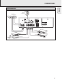
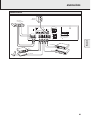
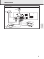
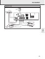
CONNECTIONS
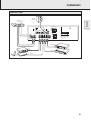
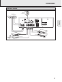
Audio connections
VIDEO IN/OUT
DVD MON TV/SAT
IN OUT
OUT
REC
IN
IN
PLAY
TV CD CDR/TAPE
AUDIO IN/OUT
L
R
IN
PLAY
OUT
REC
IN IN
IN
PLAY
OUT
REC
PRE-OUT
CENTER
6 CHANNEL / DVD INPUT
FRONTSURR.
CENTER
SUB-
WOOFER
VCR
L
R
VCR
IN
CINEMA
LINK
SUBWOOFER
PRE-OUT
ANTENNA
AM LOOP
FRONT SPEAKERS
L
R
EACH SPEAKER ≥ 6 Ω
CENTER
Designed and developed by Philips in the
European Community
CAUTION
RISK OF ELECTRIC SHOCK
DO NOT OPEN
AVIS
RISQUE DE CHOC
ELECTRIQUE
Manufactured under licence from Dolby
Laboratories Licencing Corporation.
"DOLBY", "PRO-LOGIC" and the Double-D
Symbol are Trademarks of Dolby
Laboratories Licencing Corporation.
R
L
EACH SPEAKER ≥ 6 Ω
SURROUND SPEAKERS
AUDIO IN
AUDIO OUT
IN
OUT
VCR
SAT RECEIVER
CD RECORDER
CD PLAYER
DVD PLAYER
(6 Channel Output)
POWERED
SUBWOOFER

10
English
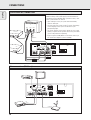
CONNECTIONS
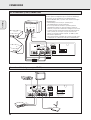
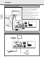
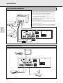
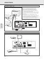
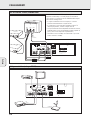
System control bus, CINEMA LINK
Video connections (FR 760 only)
VIDEO IN/OUT
DVD MON TV/SAT
IN OUT
OUT
REC
IN
IN
PLAY
TV CD CDR/TAPE
AUDIO IN/OUT
L
R
IN
PLAY
OUT
REC
IN IN
IN
PLAY
OUT
REC
PRE-OUT
CENTER
6 CHANNEL / DVD INPUT
FRONTSURR.
CENTER
SUB-
WOOFER
VCR
L
R
VCR
IN
CINEMA
LINK
SUBWOOFER
PRE-OUT
ANTENNA
AM LOOP
FRONT SPEAKERS
L
R
EACH SPEAKER ≥ 6 Ω
CENTER
Designed and developed by Philips in the
European Community
CAUTION
RISK OF ELECTRIC SHOCK
DO NOT OPEN
AVIS
RISQUE DE CHOC
ELECTRIQUE
Manufactured under licence from Dolby
Laboratories Licencing Corporation.
"DOLBY", "PRO-LOGIC" and the Double-D
Symbol are Trademarks of Dolby
Laboratories Licencing Corporation.
R
L
EACH SPEAKER ≥ 6 Ω
SURROUND SPEAKERS
DVD PLAYER
MONITOR / TV
VIDEO IN
VIDEO OUT
VCR
SAT RECEIVER
VIDEO IN/OUT
DVD MON TV/SAT
IN OUT
OUT
REC
IN
IN
PLAY
TV CD CDR/TAPE
AUDIO IN/OUT
L
R
IN
PLAY
OUT
REC
IN IN
IN
PLAY
OUT
REC
PRE-OUT
CENTER
6 CHANNEL / DVD INPUT
FRONTSURR.
CENTER
SUB-
WOOFER
VCR
L
R
VCR
IN
CINEMA
LINK
SUBWOOFER
PRE-OUT
ANTENNA
AM LOOP
FRONT SPEAKERS
L
R
EACH SPEAKER ≥ 6 Ω
CENTER
Designed and developed by Philips in the
European Community
CAUTION
RISK OF ELECTRIC SHOCK
DO NOT OPEN
AVIS
RISQUE DE CHOC
ELECTRIQUE
Manufactured under licence from Dolby
Laboratories Licencing Corporation.
"DOLBY", "PRO-LOGIC" and the Double-D
Symbol are Trademarks of Dolby
Laboratories Licencing Corporation.
R
L
EACH SPEAKER ≥ 6 Ω
SURROUND SPEAKERS
TV to AMP
AUX to AMP
TV
AUX
EXT 1 EXT 2 EXT 3
DVD PLAYER
VCR
TV
optional
(TV = CENTER)
CINEMA LINK
A
If the receiver and your Philips TV (or even better in
addition a Philips VCR or DVD player) with Cinemalink are
connected with the CINEMA LINK system bus control, some
extra system benefits are offered:
– Upon starting a source, the system will automatically
switch to that input.
– You may control the system via the TV screen. Depending
on the language of the TV, this can be done in your
preferred language.
– The TV can function as the center speaker of your system,
making a separate center speaker unnecessary. (The cable
A has to be purchased separately.)
– By pressing the standby button on the remote control you
can switch the complete system to standby.

11
English
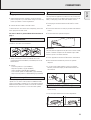
CONNECTIONS
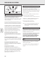
The type plate is located on the rear of the receiver.
1 Check whether the mains voltage as shown on the type
plate corresponds to your local mains voltage. If it does not,
consult your dealer or service organization.
2 Connect the mains cable to the wall socket.
To disconnect the set from the mains completely, remove the
mains plug from the wall socket.
For users in the U. K.: please follow the instructions on
page 2.
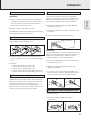
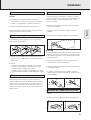
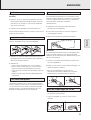
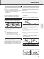
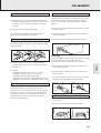
The speaker connections on the receiver are click-fit
connectors. Use them as shown below.
1 Always connect the coloured (or marked) wire to the
coloured terminal and the black (or unmarked) wire to the
black terminal.
2 Connect:
– Left front speaker to L (red and black)
– Right front speaker to R (red and black)
– Center speaker to CENTER (blue and black)
– Left surround speaker to SURROUND L (grey and black)
– Right surround speaker to SURROUND R (grey and black)
You may use your Philips TV with CINEMA LINK as the center
speaker. For TVs with a scart connector an additional audio
cinch-to-scart cable is needed. For TV’s with cinch connectors
additional cinch cables are needed. Look into the instruction
manual of your TV on how to use it as the center speaker.
AM (MW) antenna
The loop antenna supplied is for indoor use only. Position the
antenna as far away as possible from the receiver, the TV, the
cables, a DVD player, a VCR and other radiation sources.
1 Fit the plug of the frame antenna to AM LOOP as shown
below.
2 Position the antenna as far away as possible from radiation
sources.
3 Turn the antenna for optimum reception.
FM antenna
The wire antenna supplied can only be used to receive nearby
stations. For better reception we recommend using a cable
antenna system or an outdoor antenna.
1 Fit the supplied wire antenna to FM 75 Ω as shown below.
2 Move the antenna in different positions for optimum
reception.
• If you are using a cable antenna system or an outdoor
antenna, fit the antenna plug to FM 75 Ω instead of the
wire antenna.
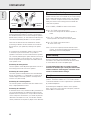
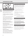
• To remove the FRONT AV / GAME cap, press on the right
side of the cap.
• Insert the cap from below to close the compartment.
PHONES
FRONT AV / GAME
PHONES
FRONT A
V / GAME
FRONT AV / GAME cap (FR 760 only)
FM 75 Ω
FM 75 Ω
AM LOOP
ANTENNA
Antenna connections
TV as the center speaker
8 mm
1
2
3
Speaker connections
Mains
La pagina si sta caricando...
La pagina si sta caricando...
La pagina si sta caricando...
La pagina si sta caricando...
La pagina si sta caricando...
La pagina si sta caricando...
La pagina si sta caricando...
La pagina si sta caricando...
La pagina si sta caricando...
La pagina si sta caricando...
La pagina si sta caricando...
La pagina si sta caricando...
La pagina si sta caricando...
La pagina si sta caricando...
La pagina si sta caricando...
La pagina si sta caricando...
La pagina si sta caricando...
La pagina si sta caricando...

30
Français
CONNEXIONS
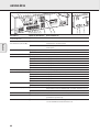
Bus de commande système, CINEMA LINK
Connexions vidéo (uniquement pour FR 760)
VIDEO IN/OUT
DVD MON TV/SAT
IN OUT
OUT
REC
IN
IN
PLAY
TV CD CDR/TAPE
AUDIO IN/OUT
L
R
IN
PLAY
OUT
REC
IN IN
IN
PLAY
OUT
REC
PRE-OUT
CENTER
6 CHANNEL / DVD INPUT
FRONTSURR.
CENTER
SUB-
WOOFER
VCR
L
R
VCR
IN
CINEMA
LINK
SUBWOOFER
PRE-OUT
ANTENNA
AM LOOP
FRONT SPEAKERS
L
R
EACH SPEAKER ≥ 6 Ω
CENTER
Designed and developed by Philips in the
European Community
CAUTION
RISK OF ELECTRIC SHOCK
DO NOT OPEN
AVIS
RISQUE DE CHOC
ELECTRIQUE
Manufactured under licence from Dolby
Laboratories Licencing Corporation.
"DOLBY", "PRO-LOGIC" and the Double-D
Symbol are Trademarks of Dolby
Laboratories Licencing Corporation.
R
L
EACH SPEAKER ≥ 6 Ω
SURROUND SPEAKERS
DVD PLAYER
MONITOR / TV
VIDEO IN
VIDEO OUT
VCR
SAT RECEIVER
Si le récepteur et votre téléviseur Philips (et mieux encore si
à cela s’ajoute un magnétoscope ou un lecteur DVD Philips)
sont reliés, par un Cinemalink, à la commande du bus
système CINEMA LINK, le système offre certains avantages
supplémentaires :
– Au démarrage d‘une source, le système passe
automatiquement à l‘entrée concernée.
–
Il vous est possible de contrôler le système à partir de
l‘équipement du téléviseur. Selon la langue au niveau du
téléviseur, ceci peut être réalisé dans la langue de votre choix.
– Le téléviseur peut fonctionner comme enceinte central de
votre système, de sorte qu‘il n‘est pas nécessaire de
prévoir une enceinte centrale séparée. (Le câble A doit
être acheté séparément.)
– Vous pouvez mettre l’ensemble du système en mode veille
en appuyant sur le bouton de veille de la télécommande.
VIDEO IN/OUT
DVD MON TV/SAT
IN OUT
OUT
REC
IN
IN
PLAY
TV CD CDR/TAPE
AUDIO IN/OUT
L
R
IN
PLAY
OUT
REC
IN IN
IN
PLAY
OUT
REC
PRE-OUT
CENTER
6 CHANNEL / DVD INPUT
FRONTSURR.
CENTER
SUB-
WOOFER
VCR
L
R
VCR
IN
CINEMA
LINK
SUBWOOFER
PRE-OUT
ANTENNA
AM LOOP
FRONT SPEAKERS
L
R
EACH SPEAKER ≥ 6 Ω
CENTER
Designed and developed by Philips in the
European Community
CAUTION
RISK OF ELECTRIC SHOCK
DO NOT OPEN
AVIS
RISQUE DE CHOC
ELECTRIQUE
Manufactured under licence from Dolby
Laboratories Licencing Corporation.
"DOLBY", "PRO-LOGIC" and the Double-D
Symbol are Trademarks of Dolby
Laboratories Licencing Corporation.
R
L
EACH SPEAKER ≥ 6 Ω
SURROUND SPEAKERS
TV to AMP
AUX to AMP
TV
AUX
EXT 1 EXT 2 EXT 3
DVD PLAYER
VCR
TV
optional
(TV = CENTER)
CINEMA LINK
A

31
Français
CONNEXIONS
La plaquette signalétique est située à l‘arrière de
l‘équipement.
1 Vérifiez si la tension secteur référencée sur la plaquette
signalétique correspond à votre tension secteur locale. Si
ce n‘est pas le cas, consultez votre concessionnaire ou
l‘organisation de service après-vente.
2 Branchez le câble secteur à la prise murale.
Pour débrancher complètement l’appareil du secteur, retirez la
fiche d’alimentation de la prise de courant.
Les connexions au niveau du récepteur sont des connecteurs
à clips. Pratiquez comme illustré ci-dessous.
1 Connectez toujours le fil en couleurs (ou référencé) à la
borne en couleurs et le fil noir (ou non référencé) à la borne
noire.
2 Connectez :
– L‘enceinte avant gauche à L (rouge et noir)
– L‘enceinte avant droite à R (rouge et noir)
– L‘enceinte central à CENTER (bleu et noir)
– L‘enceinte surround gauche à SURROUND L (gris et noir)
– L‘enceinte surround droite à SURROUND R (gris et noir)
Vous pouvez utiliser votre téléviseur Philips avec
CINEMA LINK comme enceinte centrale. Pour les téléviseurs
équipés d‘un connecteur scart, un câble cinch-to-scart audio
supplémentaire est requis. Pour les téléviseurs avec
connecteurs cinch, des câbles cinch complémentaires sont
requis. Référez-vous au manuel de votre téléviseur pour savoir
comment il peut faire fonction d‘enceinte centrale.
Antenne AM (MW)
L‘antenne-cadre comprise à la livraison est uniquement
destinée à l‘usage intérieur. Positionnez l‘antenne aussi loin
que possible du récepteur, du téléviseur, des câbles, d‘un
lecteur DVD, d‘un VCR et d‘autres sources de radiation.
1 Introduisez la fiche de l‘antenne-cadre dans AM LOOP
comme illustré ci-dessous.
2 Positionnez l‘antenne aussi loin que possible des sources
de radiation.
3 Tournez l‘antenne pour optimaliser la réception.
Antenne FM
L‘antenne-câble comprise à la livraison peut uniquement être
utilisée pour recevoir des stations proches. Pour améliorer la
réception, nous recommandons l‘usage d‘un système
d‘antenne par câble ou d‘une antenne extérieure.
1 Fixez l‘antenne-câble comprise à la livraison à FM 75 Ω
comme illustré ci-dessous.
2 Déplacez l‘antenne dans différentes positions pour
optimaliser la réception.
• Si vous utilisez un système d‘antenne par câble ou une
antenne extérieure, introduisez la fiche d‘antenne dans la
prise FM 75 Ω en lieu et place de l‘antenne prévue.
• Pour ôter le cache FRONT AV / GAME, appuyez sur le côté
droit de ce dernier.
• Introduisez le cache par le bas pour fermer le
compartiment.
PHONES
FRONT AV / GAME
PHONES
FRONT A
V / GAME
Cache FRONT AV / GAME (uniquement FR 760)
FM 75 Ω
FM 75 Ω
AM LOOP
ANTENNA
Connexions d‘antenne
Téléviseur faisant fonction d‘enceinte centrale
8 mm
1
2
3
Connexions des enceintes
Secteur
La pagina si sta caricando...
La pagina si sta caricando...
La pagina si sta caricando...
La pagina si sta caricando...
La pagina si sta caricando...
La pagina si sta caricando...
La pagina si sta caricando...
La pagina si sta caricando...
La pagina si sta caricando...
La pagina si sta caricando...
La pagina si sta caricando...
La pagina si sta caricando...
La pagina si sta caricando...
La pagina si sta caricando...
La pagina si sta caricando...
La pagina si sta caricando...
La pagina si sta caricando...
La pagina si sta caricando...

50
Español
CONEXIONES
Sistema de control en bus, CINEMA LINK
Si el receptor y la TV Philips (o incluso mejor, añadiendo un
reproductor de vídeo o de DVD Philips) con Cinemalink están
conectados con el control de barra del sistema CINEMA
LINK, se ofrecen beneficios extras para el sistema:
– Cuando inicie una fuente, el sistema selecciona
automáticamente esa entrada.
– Se puede controlar el sistema por medio de la pantalla del
televisor. Independientemente del idioma del televisor, Vd.
puede elegir el idioma que prefiera.
– El televisor puede hacer las veces de altavoz central del
sistema, haciendo innecesario el uso de un altavoz central
(El cable A debe comprarse aparte.)
– Puede poner en espera todo el sistema pulsando el botón
de puesta en espera en el mando a distancia.
Conexiones de vídeo (sólo con FR 760)
VIDEO IN/OUT
DVD MON TV/SAT
IN OUT
OUT
REC
IN
IN
PLAY
TV CD CDR/TAPE
AUDIO IN/OUT
L
R
IN
PLAY
OUT
REC
IN IN
IN
PLAY
OUT
REC
PRE-OUT
CENTER
6 CHANNEL / DVD INPUT
FRONTSURR.
CENTER
SUB-
WOOFER
VCR
L
R
VCR
IN
CINEMA
LINK
SUBWOOFER
PRE-OUT
ANTENNA
AM LOOP
FRONT SPEAKERS
L
R
EACH SPEAKER ≥ 6 Ω
CENTER
Designed and developed by Philips in the
European Community
CAUTION
RISK OF ELECTRIC SHOCK
DO NOT OPEN
AVIS
RISQUE DE CHOC
ELECTRIQUE
Manufactured under licence from Dolby
Laboratories Licencing Corporation.
"DOLBY", "PRO-LOGIC" and the Double-D
Symbol are Trademarks of Dolby
Laboratories Licencing Corporation.
R
L
EACH SPEAKER ≥ 6 Ω
SURROUND SPEAKERS
DVD PLAYER
MONITOR / TV
VIDEO IN
VIDEO OUT
VCR
SAT RECEIVER
VIDEO IN/OUT
DVD MON TV/SAT
IN OUT
OUT
REC
IN
IN
PLAY
TV CD CDR/TAPE
AUDIO IN/OUT
L
R
IN
PLAY
OUT
REC
IN IN
IN
PLAY
OUT
REC
PRE-OUT
CENTER
6 CHANNEL / DVD INPUT
FRONTSURR.
CENTER
SUB-
WOOFER
VCR
L
R
VCR
IN
CINEMA
LINK
SUBWOOFER
PRE-OUT
ANTENNA
AM LOOP
FRONT SPEAKERS
L
R
EACH SPEAKER ≥ 6 Ω
CENTER
Designed and developed by Philips in the
European Community
CAUTION
RISK OF ELECTRIC SHOCK
DO NOT OPEN
AVIS
RISQUE DE CHOC
ELECTRIQUE
Manufactured under licence from Dolby
Laboratories Licencing Corporation.
"DOLBY", "PRO-LOGIC" and the Double-D
Symbol are Trademarks of Dolby
Laboratories Licencing Corporation.
R
L
EACH SPEAKER ≥ 6 Ω
SURROUND SPEAKERS
TV to AMP
AUX to AMP
TV
AUX
EXT 1 EXT 2 EXT 3
DVD PLAYER
VCR
TV
optional
(TV = CENTER)
CINEMA LINK
A

51
Español
CONEXIONES
La placa tipo está situada en la parte posterior del
receptor.
1 Compruebe que la tensión indicada en la placa tipo
corresponde con el voltaje de la red local. De lo contrario,
consulte con su distribuidor u organización de servicio.
2 Conecte el cable de alimentación al enchufe mural.
Para desconectar por completo el equipo de la red, retirar el
conector de la toma de red de la pared.
Las conexiones de los altavoces del receptor son conexiones
de acoplamiento con clic y palanca. Siga las instrucciones
que se indican a continuación.
1 Conecte siempre el cable de color (o marcado) al terminal
del mismo color y el cable negro (o sin marcar) al terminal
de color negro.
2 Conecte:
– El altavoz frontal izquierdo al terminal L (rojo y negro)
– El altavoz frontal derecho al terminal R (rojo y negro)
– El altavoz central a CENTER (azul y negro)
–
El altavoz envolvente izquierdo a SURROUND L (gris y negro)
– El altavoz envolvente derecho a SURROUND R (gris y negro)
Puede utilizar su televisor Philips con CINEMA LINK como un
altavoz central. Para un televisor con una conexión tipo
«scart» (de alfileres) se necesita un cable adicional de audio
«cinch-to-scart». Para un televisor con conexiones «cinch» (de
clavijas) se necesitan cables «cinch» adicionales. Mire el
manual de instrucciones de su televisor para utilizarlo como
altavoz central.
Antena AM (MW)
La antena de cuadro suministrada es sólo para uso interior.
Coloque la antena tan lejos como sea posible del receptor, el
televisor, los cables, el reproductor DVD, el VCR y otras
fuentes de radiación.
1 Introduzca la clavija de la antena de cuadro en AM LOOP
como se muestra abajo.
2 Coloque la antena lo más lejos posible de fuentes de
radiación.
3 Gire y mueva la antena para obtener la mejor recepción.
Antena FM
La antena alámbrica suministrada sólo puede utilizarse para
recibir emisoras cercanas. Para obtener una recepción mejor
le recomendamos que utilice un sistema de antena por cable
o una antena exterior.
1 Conecte la antena alámbrica suministrada al terminal
FM 75 Ω como se indica a continuación.
2 Coloque la antena en diferentes posiciones hasta obtener
una recepción óptima.
• Si utiliza un sistema de antena por cable o una antena
exterior, conecte la clavija al terminal FM 75 Ω en vez de la
antena alámbrica.
• Para quitar la tapa FRONT AV / GAME, presione su lado
derecho.
• Inserte la tapa desde abajo para cerrar el compartimento.
PHONES
FRONT AV / GAME
PHONES
FRONT A
V / GAME
Tapa FRONT AV / GAME (sólo en el FR 760)
FM 75 Ω
FM 75 Ω
AM LOOP
ANTENNA
Conexiones de las antenas
El TV como altavoz central
8 mm
1
2
3
Conexiones de los altavoces
Alimentación
La pagina si sta caricando...
La pagina si sta caricando...
La pagina si sta caricando...
La pagina si sta caricando...
La pagina si sta caricando...
La pagina si sta caricando...
La pagina si sta caricando...
La pagina si sta caricando...
La pagina si sta caricando...
La pagina si sta caricando...
La pagina si sta caricando...
La pagina si sta caricando...
La pagina si sta caricando...
La pagina si sta caricando...
La pagina si sta caricando...
La pagina si sta caricando...
La pagina si sta caricando...
La pagina si sta caricando...

70
Deutsch
ANSCHLÜSSE
Falls der Receiver und Ihr Philips TV Gerät (oder noch besser
zusätzlich ein Philips VCR oder DVD-Spieler) mit Cinemalink
an den CINEMA LINK System Kontrollbus angeschlossen sind,
werden einige zusätzliche Leistungen angeboten:
– Beim Starten eines Ausgangsgerätes schaltet das System
automatisch auf diesen Eingang.
– Sie können das System über den TV-Bildschirm steuern.
Abhängig von der Sprache des TVs, können Sie dies in Ihrer
bevorzugten Sprache tun.
– Da der TV als Center Lautsprecher fungieren kann, erübrigt
sich ein separater Center Lautsprecher. (Das Kabel A muß
separat gekauft werden.)
– Durch Drücken der Bereitschaft-Taste auf der Fernbedienung
können Sie das komplette System in Bereitschaft schalten.
System Kontrollbus, CINEMA LINK
Videoanschlüsse (nur FR 760)
VIDEO IN/OUT
DVD MON TV/SAT
IN OUT
OUT
REC
IN
IN
PLAY
TV CD CDR/TAPE
AUDIO IN/OUT
L
R
IN
PLAY
OUT
REC
IN IN
IN
PLAY
OUT
REC
PRE-OUT
CENTER
6 CHANNEL / DVD INPUT
FRONTSURR.
CENTER
SUB-
WOOFER
VCR
L
R
VCR
IN
CINEMA
LINK
SUBWOOFER
PRE-OUT
ANTENNA
AM LOOP
FRONT SPEAKERS
L
R
EACH SPEAKER ≥ 6 Ω
CENTER
Designed and developed by Philips in the
European Community
CAUTION
RISK OF ELECTRIC SHOCK
DO NOT OPEN
AVIS
RISQUE DE CHOC
ELECTRIQUE
Manufactured under licence from Dolby
Laboratories Licencing Corporation.
"DOLBY", "PRO-LOGIC" and the Double-D
Symbol are Trademarks of Dolby
Laboratories Licencing Corporation.
R
L
EACH SPEAKER ≥ 6 Ω
SURROUND SPEAKERS
DVD PLAYER
MONITOR / TV
VIDEO IN
VIDEO OUT
VCR
SAT RECEIVER
VIDEO IN/OUT
DVD MON TV/SAT
IN OUT
OUT
REC
IN
IN
PLAY
TV CD CDR/TAPE
AUDIO IN/OUT
L
R
IN
PLAY
OUT
REC
IN IN
IN
PLAY
OUT
REC
PRE-OUT
CENTER
6 CHANNEL / DVD INPUT
FRONTSURR.
CENTER
SUB-
WOOFER
VCR
L
R
VCR
IN
CINEMA
LINK
SUBWOOFER
PRE-OUT
ANTENNA
AM LOOP
FRONT SPEAKERS
L
R
EACH SPEAKER ≥ 6 Ω
CENTER
Designed and developed by Philips in the
European Community
CAUTION
RISK OF ELECTRIC SHOCK
DO NOT OPEN
AVIS
RISQUE DE CHOC
ELECTRIQUE
Manufactured under licence from Dolby
Laboratories Licencing Corporation.
"DOLBY", "PRO-LOGIC" and the Double-D
Symbol are Trademarks of Dolby
Laboratories Licencing Corporation.
R
L
EACH SPEAKER ≥ 6 Ω
SURROUND SPEAKERS
TV to AMP
AUX to AMP
TV
AUX
EXT 1 EXT 2 EXT 3
DVD PLAYER
VCR
TV
optional
(TV = CENTER)
CINEMA LINK
A

71
Deutsch
ANSCHLÜSSE
Das Typenschild befindet sich an der Rückseite des
Receivers.
1 Prüfen Sie, ob die am Typenschild angegebene Spannung
mit der örtlichen Netzspannung übereinstimmt. Sollte dies
nicht der Fall sein, wenden Sie sich an Ihren Fachhändler
oder an Ihre Servicestelle.
2 Schließen Sie das Netzkabel an die Netzsteckdose an.
Um das Gerät vollständig vom Netz zu trennen, ziehen Sie den
Stecker aus der Steckdose.
Die Lautsprecheranschlüsse am Receiver sind Schnapp-
klemmen. Verwenden Sie diese wie unten abgebildet.
1 Verbinden Sie immer die farbige (oder markierte) Ader mit
der farbigen Klemme und die schwarze (oder unmarkierte)
Ader mit der schwarzen Klemme.
2 Verbinden Sie:
– Linker vorderer Lautsprecher mit L (rot und schwarz)
– Rechter vorderer Lautsprecher mit R (rot und schwarz)
– Center Lautsprecher mit CENTER (blau und schwarz)
– Linker Surround Lautsprecher mit SURROUND L (grau und
schwarz)
– Rechter Surround Lautsprecher mit SURROUND R (grau
und schwarz)
Sie können Ihren Philips TV mit CINEMA LINK als Center
Lautsprecher verwenden. Für TVs mit einem Scart Anschluß
wird ein zusätzliches Audio Cinch-an-Scart Kabel benötigt. Für
TVs mit Cinch Anschlüssen werden zusätzliche Cinch Kabel
benötigt. Befolgen Sie die Bedienungsanleitung Ihres TV’s
bezüglich der Verwendung als Center Lautsprecher.
AM (MW) Antenne
Die mitgelieferte Rahmenantenne ist ausschließlich für den
Gebrauch in Räumen bestimmt. Positionieren Sie die Antenne
soweit wie möglich entfernt vom Receiver, TV, den Kabeln,
einem DVD-Spieler, einem VCR und anderen
Strahlungsquellen.
1 Verbinden Sie den Stecker der Rahmenantenne mit
AM LOOP wie unten abgebildet.
2 Positionieren Sie die Antenne soweit wie möglich von
Strahlungsquellen entfernt.
3 Richten Sie die Antenne für optimalen Empfang aus.
FM Antenne
Die mitgelieferte Drahtantenne kann nur zum Empfang naher
Sender verwendet werden. Für einen besseren Empfang
empfehlen wir die Verwendung eines Kabelantennen-Systems
oder einer Außenantenne.
1 Stecken Sie die mitgelieferte Drahtantenne an FM 75 Ω
wie unten abgebildet an.
2 Bewegen Sie die Antenne in verschiedene Richtungen, um
optimalen Empfang zu erhalten.
• Falls Sie ein Kabelantennen-System oder eine
Außenantenne verwenden, verbinden Sie anstelle der
Drahtantenne den Antennenstecker mit FM 75 Ω .
• Um die FRONT AV / GAME Kappe zu entfernen, drücken Sie
auf die rechte Seite der Kappe.
• Setzen Sie die Kappe von unten ein, um das Fach zu
schließen.
PHONES
FRONT AV / GAME
PHONES
FRONT A
V / GAME
FRONT AV / GAME Kappe (nur FR 760)
FM 75 Ω
FM 75 Ω
AM LOOP
ANTENNA
Antennenanschlüsse
TV als Center Lautsprecher
8 mm
1
2
3
Lautsprecheranschlüsse
Netzbetrieb
La pagina si sta caricando...
La pagina si sta caricando...
La pagina si sta caricando...
La pagina si sta caricando...
La pagina si sta caricando...
La pagina si sta caricando...
La pagina si sta caricando...
La pagina si sta caricando...
La pagina si sta caricando...
La pagina si sta caricando...
La pagina si sta caricando...
La pagina si sta caricando...
La pagina si sta caricando...

BEDIENINGSKNOPPEN
85
1 POWER / STANDBY.......Om de receiver aan en uit te
zetten.
2 CINEMA LINK ................Om de systeembus tussen de
receiver en de tv in en uit te
schakelen.
3 ..........................................Sensor voor de
infraroodafstandsbediening.
4 ..........................................Display
5 SOURCE SELECTOR ......Om te kiezen tussen de
verschillende audio- en
videoaansluitingen.
6 VOLUME..........................Om het volumeniveau hoger of
lager in te stellen.
7 FRONT AV.......................Om de ingang FRONT AV / GAME
te kiezen (enkel bij de FR 760).
8 TREBLE............................Om, indien gebruikt combinatie
met VOLUME, de hoge tonen in
te stellen.
9 BASS...............................Om, indien gebruikt combinatie
met VOLUME, de lage tonen in
te stellen.
0 LOUDNESS.....................Om de LOUDNESS-functie in en
uit te schakelen.
! NEXT 2 ...........................TUNER: om een zender te
zoeken.
MENU: om naar het volgende
menuniveau te gaan.
@ ENTER / OK.....................Om de keuzes binnen een menu
te bevestigen.
# TUNER PRESET X MENU NAVIGATOR
TUNER: om de volgende of
vorige geprogrammeerde zender
te kiezen.
MENU: om naar boven en
beneden te lopen in een menu.
$ 1 PREV. / EXIT ...............TUNER: om een zender te zoeken.
MENU: om naar het vorige
menuniveau te gaan.
% SETUP MENU ................Om het menu te openen en te
sluiten.
^ SENS. ..............................Om een hoge of lage
afstemgevoeligheid in te stellen.
& NEWS/TA........................Om de RDS-nieuwsbericht- en
RDS-verkeersinformatiefuncties
in en uit te schakelen.
* TUNER AM/FM ..............Om het golfgebied van de tuner
te kiezen.
( RADIO TEXT ...................Om door de verschillende
soorten RDS-informatie te lopen.
) SURR. MODE..................Doorloopt de verschillende
luidsprekerconfiguraties.
¡ HALL................................Om de HALL-functie in en uit te
schakelen.
™ SURROUND ON/OFF .....Schakelt tussen de laatst
geselecteerde surround modus
en stereo.
POWER / STANDBY
CINEMA LINK
PHONES
CINEMA SOUND CENTER
LOUDNESS
BASS
TREBLE
AV
SOURCE SELECTOR
VOLUME
SURROUND
SURR. MODE
HALL
TUNER AM/FM
RADIO TEXT
SENS.
NEWS/TA
PREV. / EXIT
SETUP MENU
NEXT
TER / OK
ON/OFF
MENU
NAVIGATOR
TUNER
PRESET
FRONT AV / GAME
6CH/DVD
1 23 4 5
6
7
8
9
0!@#$%^&*()¡™
Nederlands
La pagina si sta caricando...
La pagina si sta caricando...
La pagina si sta caricando...
La pagina si sta caricando...

90
Nederlands
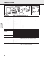
AANSLUITINGEN
Systeembus, CINEMA LINK
Videoaansluitingen (enkel bij de FR 760)
Als de receiver en uw Philips TV (of nog beter met extra
Philips VCR of DVD-speler) met CinemaLink worden
aangesloten op het CINEMA LINK-systeembussturing,
worden enige extra systeemmogelijkheden geboden:
– Wanneer u een geluidsbron inschakelt dan schakelt het
systeem automatisch naar die ingang.
– U kunt het systeem bedienen via het tv-scherm. Afhankelijk
van de talen waarover uw tv beschikt, kan dat in een taal
naar keuze.
– De tv kan dienst doen als middenluidspreker van uw
systeem zodat u geen aparte middenluidspreker nodig heeft.
(De kabel A moet afzonderlijk worden aangekocht.)
– Door op de standby-knop van de afstandsbediening te drukken,
kunt u het volledige systeem overschakelen op standby.
VIDEO IN/OUT
DVD MON TV/SAT
IN OUT
OUT
REC
IN
IN
PLAY
TV CD CDR/TAPE
AUDIO IN/OUT
L
R
IN
PLAY
OUT
REC
IN IN
IN
PLAY
OUT
REC
PRE-OUT
CENTER
6 CHANNEL / DVD INPUT
FRONTSURR.
CENTER
SUB-
WOOFER
VCR
L
R
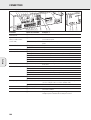
VCR
IN
CINEMA
LINK
SUBWOOFER
PRE-OUT
ANTENNA
AM LOOP
FRONT SPEAKERS
L
R
EACH SPEAKER ≥ 6 Ω
CENTER
Designed and developed by Philips in the
European Community
CAUTION
RISK OF ELECTRIC SHOCK
DO NOT OPEN
AVIS
RISQUE DE CHOC
ELECTRIQUE
Manufactured under licence from Dolby
Laboratories Licencing Corporation.
"DOLBY", "PRO-LOGIC" and the Double-D
Symbol are Trademarks of Dolby
Laboratories Licencing Corporation.
R
L
EACH SPEAKER ≥ 6 Ω
SURROUND SPEAKERS
DVD PLAYER
MONITOR / TV
VIDEO IN
VIDEO OUT
VCR
SAT RECEIVER
VIDEO IN/OUT
DVD MON TV/SAT
IN OUT
OUT
REC
IN
IN
PLAY
TV CD CDR/TAPE
AUDIO IN/OUT
L
R
IN
PLAY
OUT
REC
IN IN
IN
PLAY
OUT
REC
PRE-OUT
CENTER
6 CHANNEL / DVD INPUT
FRONTSURR.
CENTER
SUB-
WOOFER
VCR
L
R
VCR
IN
CINEMA
LINK
SUBWOOFER
PRE-OUT
ANTENNA
AM LOOP
FRONT SPEAKERS
L
R
EACH SPEAKER ≥ 6 Ω
CENTER
Designed and developed by Philips in the
European Community
CAUTION
RISK OF ELECTRIC SHOCK
DO NOT OPEN
AVIS
RISQUE DE CHOC
ELECTRIQUE
Manufactured under licence from Dolby
Laboratories Licencing Corporation.
"DOLBY", "PRO-LOGIC" and the Double-D
Symbol are Trademarks of Dolby
Laboratories Licencing Corporation.
R
L
EACH SPEAKER ≥ 6 Ω
SURROUND SPEAKERS
TV to AMP
AUX to AMP
TV
AUX
EXT 1 EXT 2 EXT 3
DVD PLAYER
VCR
TV
optional
(TV = CENTER)
CINEMA LINK
A

91
Nederlands
AANSLUITINGEN
Het typeplaatje bevindt zich op de achterkant van de
receiver.
1 Controleer of de netspanning op het typeplaatje
overeenkomt met de plaatselijke netspanning. Is dit niet het
geval, neem dan contact op met uw leverancier of
serviceorganisatie.
2 Verbind het netsnoer met het stopcontact.
Om het toestel volledig van het net te scheiden moet de
netstekker uit de muurcontactdoos worden getrokken.
De luidsprekeraansluitingen op de receiver zijn
klemaansluitingen. Sluit aan zoals hieronder aangegeven.
1 Sluit altijd de gekleurde (of gemerkte) draad aan op de
gekleurde aansluiting en de zwarte (of niet-gemerkte) draad
op de zwarte aansluiting.
2 Verbind:
– De linkervoorluidspreker met L (rood en zwart)
– De rechtervoorluidspreker met R (rood en zwart)
– De middenluidspreker met (blauw en zwart)
– De linker-surround-luidspreker met SURROUND L (grijs
en zwart)
– De rechter-surround-luidspreker met SURROUND R (grijs
en zwart)
U kunt uw Philips-tv met CINEMA LINK als middenluidspreker
gebruiken. Voor tv’s met een scart-aansluiting heeft u een
extra audioverloopkabel (van cinch naar scart) nodig. Voor tv’s
met cinch-aansluitingen heeft u extra cinch-kabels nodig. Kijk
in de gebruiksaanwijzing van uw tv om te weten hoe u uw tv
als middenluidspreker kunt gebruiken.
AM (MW)-antenne
De raamantenne is uitsluitend voor gebruik binnenshuis.
Plaats de antenne zo ver mogelijk uit de buurt van de receiver,
de tv, de kabels, een DVD-speler, een viderecorder of andere
stralingsbronnen.
1 Sluit de stekker van de raamantenne aan op AM LOOP
zoals hieronder aangegeven.
2 Plaats de antenne zo ver mogelijk uit de buurt van
stralingsbronnen.
3 Draai de antenne voor een zo goed mogelijke ontvangst.
FM-antenne
De bijgeleverde draadantenne dient enkel voor het ontvangen
van zenders in de buurt. Voor een betere ontvangst adviseren
wij u gebruik te maken van het kabelantennesysteem of van
een buitenantenne.
1 Sluit de bijgeleverde draadantenne aan op FM 75 Ω zoals
hieronder aangegeven.
2 Zet de antenne in verschillende standen voor een zo goed
mogelijke ontvangst.
• Als u gebruik maakt van het kabelantennesysteem of van
een buitenantenne, sluit deze dan aan op FM 75 Ω in
plaats van de draadantenne.
• Om de FRONT AV / GAME kap te verwijderen, moet u aan
de rechterkant van de kap drukken.
• Zet de kap in langs onder om het compartiment af te
sluiten.
PHONES
FRONT AV / GAME
PHONES
FRONT A
V / GAME
FRONT AV / GAME kap (enkel bij de FR 760)
FM 75 Ω
FM 75 Ω
AM LOOP
ANTENNA
Antenneaansluitingen
Uw tv als middenluidspreker
8 mm
1
2
3
Luidsprekeraansluitingen
Netaansluiting
La pagina si sta caricando...
La pagina si sta caricando...
La pagina si sta caricando...
La pagina si sta caricando...
La pagina si sta caricando...
La pagina si sta caricando...
La pagina si sta caricando...
La pagina si sta caricando...
La pagina si sta caricando...
La pagina si sta caricando...
La pagina si sta caricando...
La pagina si sta caricando...

INFORMAZIONI GENERALI
104
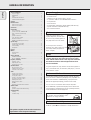
Questo ricevitore viene fornito completo di:
– un telecomando
– 2 batterie per il telecomando, formato AA
– un cavo bus di sistema per il collegamento CINEMA LINK
– un’antenna a telaio
– un’antenna metallica
–
5 altoparlanti, compresi 5 cavi per altoparlante (solo per MX 740)
– una scheda per installazione rapida (solo per MX 740)
– questo manuale di istruzioni
Pulire il ricevitore con un panno
morbido e non peloso, leggermente
inumidito. Non usare detergenti,
perché possono avere un’azione
corrosiva.
Non esporre il ricevitore ad umidità,
pioggia, sabbia o calore eccessivo
(generato dall’impianto di
riscaldamento o dai raggi solari diretti).
Se i componenti del sistema sono impilati, il ricevitore
deve essere posizionato in cima ad essi. Poggiare il
ricevitore su una superficie in piano, solida e stabile.
Non coprire le aperture di ventilazione e lasciare una
distanza libera per la ventilazione pari a 50 cm al di
sopra ed a 10 cm a sinistra e a destra del ricevitore.
Per una buona ricezione, non posizionare l’antenna a telaio al
di sopra o al di sotto di VCR, registratori CD, lettori DVD, TV
ed altre sorgenti di radiazioni.
Non è stato utilizzato materiale d’imballaggio in eccesso. È stato
fatto il possibile per rendere il materiale d’imballaggio facilmente
scomponibile in tre monomateriali: cartone (scatola), polistirene
espanso (paracolpi) e polietilene (buste, fogli protettivi in espanso).
L’apparecchio è composto da materiali che possono essere
riciclati, se smontati da una ditta specializzata. Rispettare le
norme locali sullo smaltimento dei materiali di imballaggio,
batterie esaurite ed apparecchiature obsolete.
«DOLBY», «DOLBY DIGITAL», «PRO LOGIC» ed il simbolo con la
doppia D 2 sono marchi di fabbrica della Dolby Laboratories.
Riconoscimento dei marchi di fabbrica
Informazioni ambientali
Regolazione
Manutenzione
Materiale in dotazione
Informazioni generali
Materiale in dotazione...................................................................104
Manutenzione ................................................................................104
Regolazione....................................................................................104
Informazioni ambientali .................................................................104
Riconoscimento dei marchi di fabbrica .........................................104
Comandi ............................................................................................105
Telecomando
Uso del telecomando .....................................................................106
Pulsanti del telecomando ..............................................................107
Connettori .........................................................................................108
Collegamenti
Collegamenti audio........................................................................109
Bus di controllo del sistema, CINEMA LINK .................................110
Collegamenti video (solo per FR 760)............................................110
Rete ................................................................................................111
Collegamenti degli altoparlanti .....................................................111
TV come altoparlante centrale ......................................................111
Collegamenti dell’antenna.............................................................111
FRONT AV / GAME cap (solo FR 760)............................................111
Regolazione del sistema
Posizionamento degli altoparlanti .................................................112
Regolazione e test degli altoparlanti.............................................112
Controllo dell’alimentazione..........................................................112
Cuffie..............................................................................................112
Display...............................................................................................113
Menu
Menu del ricevitore........................................................................114
Menu della TV................................................................................115
Selezione sorgente
SOURCE SELECTOR........................................................................116
Informazioni su 6 CHANNEL / DVD INPUT....................................116
Riproduzione, registrazione
Riproduzione di una sorgente........................................................117
Regolazione del suono...................................................................117
Registrazione da una sorgente......................................................117
Suono surround
Informazioni sul suono surround....................................................118
Attivazione del suono surround.....................................................118
Regolazioni del suono surround.....................................................118
Sintonizzatore
Sintonizzazione sulle stazioni radio...............................................119
Attivazione della sensibilità FM....................................................119
Memorizzazione delle stazioni radio .............................................119
Sintonizzazione sulle stazioni radio memorizzate .........................120
Riordinamento delle stazioni radio memorizzate ..........................120
Denominazione delle stazioni radio...............................................120
Cancellazione dei nomi delle stazioni ...........................................120
RDS R............................................................................................121
Notiziario RDS ed Informazioni sul traffico...................................121
Dati tecnici
Ricevitore .......................................................................................122
Altoparlanti (forniti solo con MX 740)...........................................122
Individuazione dei malfunzionamenti
Attenzione......................................................................................123
Individuazione dei malfunzionamenti ............................................123
Italiano
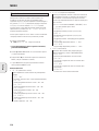
Questo apparecchio soddisfa i requisiti previsti
dalle normative della Comunità Europea in materia
di radiointerferenze.
Come partner ENERGY STAR
®
Philips ha constatato che questo
prodotto soddisfa le direttive ENERGY STAR
®
in
materia di efficienza energetica.

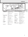
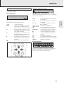
COMANDI
105
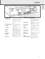
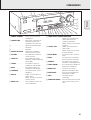
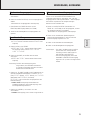
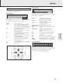
1 POWER / STANDBY.......Accende e spegne il ricevitore.
2 CINEMA LINK ................Accende e spegne il bus di
controllo del sistema tra il
ricevitore e la TV.
3 ..........................................Sensore per il telecomando a
raggi infrarossi.
4 ..........................................Display
5 SOURCE SELECTOR ......Seleziona i diversi connettori
audio e video.
6 VOLUME..........................Aumenta e diminuisce il livello
del volume.
7 FRONT AV.......................Seleziona l’entrata FRONT AV /
GAME (solo per FR 760).
8 TREBLE............................Regola i toni acuti, se utilizzato
con VOLUME.
9 BASS...............................Regola i toni bassi, se utilizzato
con VOLUME.
0 LOUDNESS.....................Accende e spegne LOUDNESS.
! NEXT 2 ...........................TUNER: ricerca le stazioni radio.
MENU: porta al livello
successivo di menu.
@ ENTER / OK.....................Conferma i valori di menu
selezionati.
# TUNER PRESET X MENU NAVIGATOR
TUNER: porta alla precedente o
successiva stazione radio
memorizzata.
MENU: sposta verso l’alto e
verso il basso.
$ 1 PREV. / EXIT ...............TUNER: ricerca le stazioni radio.
MENU: porta al livello
precedente di menu.
% SETUP MENU ................Attiva e disattiva il menu.
^ SENS. ..............................Sposta fra sensibilità alta e
bassa del sintonizzatore.
& NEWS/TA........................Attiva e disattiva il notiziario RDS
e le informazioni sul traffico RDS.
* TUNER AM/FM Sposta fra le gamme di lunghezze
d’onda del sintonizzatore.
( RADIO TEXT ...................
Scorre le diverse informazioni RDS.
) SURR. MODE..................Si sposta attraverso le diverse
configurazioni dell’altoparlante.
¡ HALL................................Accende e spegne HALL.
™ SURROUND ON/OFF .....Si sposta tra le tipologie
surround e stereo selezionate
per ultime.
POWER / STANDBY
CINEMA LINK
PHONES
CINEMA SOUND CENTER
LOUDNESS
BASS
TREBLE
AV
SOURCE SELECTOR
VOLUME
SURROUND
SURR. MODE
HALL
TUNER AM/FM
RADIO TEXT
SENS.
NEWS/TA
PREV. / EXIT
SETUP MENU
NEXT
TER / OK
ON/OFF
MENU
NAVIGATOR
TUNER
PRESET
FRONT AV / GAME
6CH/DVD
1 23 4 5
6
7
8
9
0!@#$%^&*()¡™
Italiano

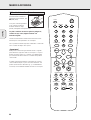
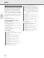
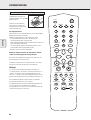
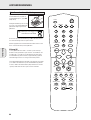
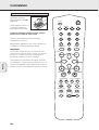
TELECOMANDO
106
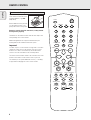
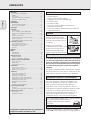
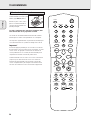
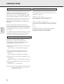
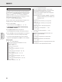
Aprire il comparto batterie del
telecomando ed inserirvi
2 batterie alcaline di tipo AA
(R06, UM-3).
Estrarre le batterie esaurite o se
si pensa di non utilizzare il
telecomando per lungo tempo.
Le batterie contengono sostanze chimiche, pertanto
devono essere smaltite in modo corretto.
I pulsanti sul telecomando funzionano come quelli
corrispondenti sul ricevitore.
Apparecchiature aggiuntive possono essere controllate solo
se operano con il sistema di codici RC-5 ed RC-6.
Importante!
Per spostare la sorgente del suono sul ricevitore bisogna
premere il tasto relativo per più di 1 secondo. Se lo si preme
per meno di 1 secondo si trasferisce al telecomando la
gestione dei comandi per il prodotto selezionato.
Il telecomando resta sintonizzato sulla sorgente selezionata
sino a quando non si preme un altro pulsante dello stesso. Ciò
consente di azionare delle sorgenti aggiuntive (ad esempio di
avvolgere un nastro), senza cambiare la sorgente sul ricevitore.
Uso del telecomando
2
AA
TV
MENU
H
1
3
2
4
6
5
7
9
8
0
+
b
-
íëÅ
Ç
É
±
DVD/6CH
OK
CINEMA LINK
GUIDE
DISC
FR.D/INDEXPAUSE
SURR. ON/OFFDISPLAY/T-C NEWS/TA
SURR. MODESMART SOUND
REAR
CHANNEL
TEST TONELOUDNESS
CHANNEL/TRACK
TUNER
CD CDR/TAPE VCR TV
Italiano

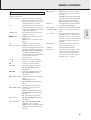
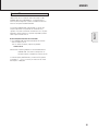
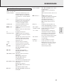
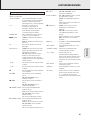
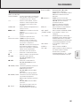
TELECOMANDO
107
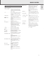
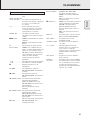
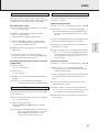
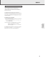
2 ................................Mette il ricevitore in modo standby.
TUNER, CD, CDR/TAPE,
TV, VCR, DVD/6CH........Sposta il telecomando sui comandi dei
diversi prodotti. Seleziona le sorgenti
se premuto per più di 1 secondo.
1–0................................Immette i numeri di brani, stazioni o
frequenze. I numeri composti da due
cifre devono essere immessi entro
2 secondi.
CINEMA LINK...............Attiva e disattiva il collegamento fra il
ricevitore e la TV.
MENU GUIDE ..............TUNER: attiva e disattiva il menu del
ricevitore.
DVD, TV: attiva e disattiva il menu
DVD/TV.
OK.................................Conferma le opzioni del menu.
Pulsanti con le frecce...TUNER: Consente di spostarsi
attraverso il menu. Le frecce verso
sinistra/verso destra spostano nella
sintonia verso l’alto/il basso.
CD, CDR: Le frecce verso sinistra/verso
destra ricercano indietro/in avanti, le
frecce verso l’alto/il basso selezionano
il brano successivo/precedente.
+A...........................Aumenta il volume del ricevitore.
-A...........................Diminuisce il volume del ricevitore.
H ................................Mette in sordina il sonoro del ricevitore.
ÉATV ......................Aumenta il volume della TV.
CD, CDR, VCR, DVD: Avvia la
riproduzione.
ÇATV ......................Diminuisce il volume della TV.
CD, CDR, VCR, DVD: Arresta la
riproduzione.
í
CHANNEL/TRACK
...Seleziona la precedente stazione del
sintonizzatore preimpostata.
VCR: Riavvolge il nastro.
CD, CDR, DVD: Seleziona il brano
precedente.
TV: Seleziona il canale precedente.
ë
CHANNEL/TRACK
...Seleziona la successiva stazione del
sintonizzatore preimpostata.
VCR: Avvolge velocemente in avanti il
nastro.
CD, CDR, DVD: Seleziona il brano
successivo.
TV: Seleziona il canale successivo.
Å PAUSE...................CD, CDR, VCR, DVD: Arresta
momentaneamente la riproduzione.
DISC FR.D./INDEX ........Variatori di CD-, CDR-, DVD:
Sposta al disco successivo.
TUNER: Sposta su FREQUENCY DIRECT.
VCR: Attiva e disattiva la ricerca
dell’indice.
b DISPLAY/T-C...........TUNER: Sposta fra nome della
stazione, frequenza e testo della radio.
CD, CDR: Sposta fra le diverse
visualizzazioni dell’ora.
TV: Attiva e disattiva il televideo.
DVD: Sposta fra titolo e capitolo.
NEWS/TA .....................Attiva e disattiva le funzioni NEWS e
TRAFFIC ANNOUNCEMENT.
SURR. ON/OFF..............Attiva e disattiva SURROUND SOUND.
±SMART SOUND ......Scorre attraverso i diversi suoni
intelligenti.
+/- REAR ...............Aumenta/diminuisce il volume degli
altoparlanti posteriori. Mentre è attivo il
rivelatore acustico di test, è possibile
aumentare/diminuire con questi pulsanti
il volume degli altoparlanti in funzione.
SURR. MODE................Scorre attraverso i diversi modi
surround.
LOUDNESS ...................Attiva e disattiva LOUDNESS.
TEST TONE ...................Attiva e disattiva il rivelatore acustico di
test. Mentre è attivo il rivelatore
acustico di test, è possibile
aumentare/diminuire con +/- REAR
il volume degli altoparlanti in funzione.
Pulsanti del telecomando
Italiano

108
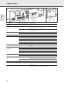
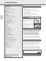
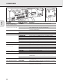
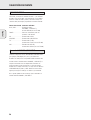
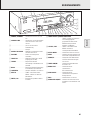
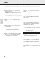
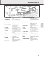
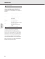
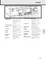
CONNETTORI
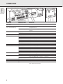
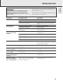
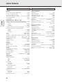
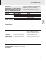
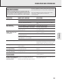
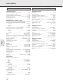
Connettori Nome del connettore Collegare a :
Presa cuffie 6,3 mm 1 PHONES Cuffia con spina da 6,3 mm.
anteriormente.
Ingressi sorgenti anteriori 2 FRONT AV / GAME Prese audio di destra e di sinistra per accessori quali le video
camere e audio e video le consolle dei giochi.
(solo FR 760)
3 FRONT AV / GAME Prese video per accessori quali le video camere e le consolle dei
giochi.
FRONT SPEAKERS 4 R, L Altoparlante anteriore sinistro e destro.
5 CENTER Altoparlante centrale.
SURROUND SPEAKERS 6 R, L Altoparlante surround sinistro e destro.
AUDIO IN/OUT 8 CDR/TAPE OUT Entrata di un registratore CD o di una piastra di registrazione.
9 CDR/TAPE IN Uscita di un registratore CD o di una piastra di registrazione.
0 CD IN Uscita di un lettore di CD.
! TV IN Uscita di una TV.
@ VCR OUT Entrata di un videoregistratore.
# VCR IN Uscita di un videoregistratore.
Entrata a 6 canali $
6 CHANNEL /DVD INPUT
Uscita a 6 canali di apparecchiature, come riproduttori DVD o di
dischi laser.
VIDEO IN/OUT (solo per FR 760) % DVD IN Uscita di un riproduttore DVD.
^ MON OUT Entrata di un monitor (ad es. la TV).
* VCR IN Uscita di un videoregistratore.
( VCR OUT Entrata di un videoregistratore (per registrare).
¡ TV IN Uscita di una TV.
Connettori dell’antenna &
AM LOOP
Antenna a telaio in dotazione.
) FM 75 Ω Antenna metallica in dotazione o antenna esterna.
Uscite preamplificate 7 CENTER PRE-OUT Entrata di una TV, se utilizzata come altoparlante centrale (possibile
solo se è collegato il bus di sistema CINEMA LINK).
™
SUBWOOFER PRE-OUT
Entrata di un subwoofer alimentato.
Bus di controllo del sistema £ CINEMA LINK Prese bus di controllo del sistema di una TV Philips con CINEMA LINK.
Presa di alimentazione ≤ AC OUTLET Alimenta la stessa tensione di rete. Carico totale massimo
consentito di 100 W.
Conduttore di rete ∞ Dopo avere eseguito tutti gli altri collegamenti,
collegare questo conduttore di rete alla presa a muro.
POWER / STANDBY
CINEMA LINK
PHONES
SURROU
N
ON/O
F
TOTAL 100W MAX. SWITCHED
AC OUTLET
230V
~50 Hz
CAUTION
RISK OF ELECTRIC SHOCK
DO NOT OPEN
AVIS
RISQUE DE CHOC ELECTRIQUE
NE PAS OUVRIR
Designed
and
developed
by Philips
in the
European Community
IN
PLAY
OUT
REC
IN
PLAY
OUT
REC
IN
IN
OUT
OUT
REC
IN
PLAY
ANTENNA
FM
75
Ω
VIDEO IN/OUT
AM LOOP
DVD
MON
VCR
TV
SUBWOOFER
PRE-OUT
VCR
TV
CD
CDR/T
APE
AUDIO IN/OUT
IN
IN
PRE-OUT
CENTER
Manufactured
under
licence
from
Dolby
Laboratories
Licencing
Corporation.
"DOLBY",
"PRO-LOGIC"
and the Double-D
Symbol
are Trademarks
of Dolby
Laboratories
Licencing
Corporation.
FRONT SPEAKERS
L
R
EACH SPEAKER
≥ 6 Ω
CENTER
SURROUND SPEAKERS
R
L
EACH SPEAKER ≥ 3 Ω
L
R
L
R
FRONT
SURR.
CENTER
SUB-
WOOFER
6 CHANNEL / DVD INPUT
CINEMA
LINK
124567890!@#
$
%^&*() ¡™ ≤ ∞
£
3
Italiano
La pagina si sta caricando...
La pagina si sta caricando...
La pagina si sta caricando...
La pagina si sta caricando...
La pagina si sta caricando...
La pagina si sta caricando...
La pagina si sta caricando...
La pagina si sta caricando...
La pagina si sta caricando...
La pagina si sta caricando...
La pagina si sta caricando...
La pagina si sta caricando...
La pagina si sta caricando...
La pagina si sta caricando...
La pagina si sta caricando...
La pagina si sta caricando...
-
 1
1
-
 2
2
-
 3
3
-
 4
4
-
 5
5
-
 6
6
-
 7
7
-
 8
8
-
 9
9
-
 10
10
-
 11
11
-
 12
12
-
 13
13
-
 14
14
-
 15
15
-
 16
16
-
 17
17
-
 18
18
-
 19
19
-
 20
20
-
 21
21
-
 22
22
-
 23
23
-
 24
24
-
 25
25
-
 26
26
-
 27
27
-
 28
28
-
 29
29
-
 30
30
-
 31
31
-
 32
32
-
 33
33
-
 34
34
-
 35
35
-
 36
36
-
 37
37
-
 38
38
-
 39
39
-
 40
40
-
 41
41
-
 42
42
-
 43
43
-
 44
44
-
 45
45
-
 46
46
-
 47
47
-
 48
48
-
 49
49
-
 50
50
-
 51
51
-
 52
52
-
 53
53
-
 54
54
-
 55
55
-
 56
56
-
 57
57
-
 58
58
-
 59
59
-
 60
60
-
 61
61
-
 62
62
-
 63
63
-
 64
64
-
 65
65
-
 66
66
-
 67
67
-
 68
68
-
 69
69
-
 70
70
-
 71
71
-
 72
72
-
 73
73
-
 74
74
-
 75
75
-
 76
76
-
 77
77
-
 78
78
-
 79
79
-
 80
80
-
 81
81
-
 82
82
-
 83
83
-
 84
84
-
 85
85
-
 86
86
-
 87
87
-
 88
88
-
 89
89
-
 90
90
-
 91
91
-
 92
92
-
 93
93
-
 94
94
-
 95
95
-
 96
96
-
 97
97
-
 98
98
-
 99
99
-
 100
100
-
 101
101
-
 102
102
-
 103
103
-
 104
104
-
 105
105
-
 106
106
-
 107
107
-
 108
108
-
 109
109
-
 110
110
-
 111
111
-
 112
112
-
 113
113
-
 114
114
-
 115
115
-
 116
116
-
 117
117
-
 118
118
-
 119
119
-
 120
120
-
 121
121
-
 122
122
-
 123
123
-
 124
124


Philips FR 740 & FR740 Manuale del proprietario
- Categoria
- Radio
- Tipo
- Manuale del proprietario
in altre lingue
- English: Philips FR 740 & FR740 Owner's manual
- français: Philips FR 740 & FR740 Le manuel du propriétaire
- español: Philips FR 740 & FR740 El manual del propietario
- Deutsch: Philips FR 740 & FR740 Bedienungsanleitung
- Nederlands: Philips FR 740 & FR740 de handleiding