Blade Blade mCX2 Manuale del proprietario
- Categoria
- Giocattoli telecomandati
- Tipo
- Manuale del proprietario

Instruction Manual | Bedienungsanleitung
Manuel d’utilisation | Manuale di Istruzioni
RTF
CAUTION: Attempting to fly the helicopter without completely reading the manual may cause injury to yourself and people
in the vicinity, as well as damage to the helicopter.
ACHTUNG: Der Versuch, den Helikopter zu fliegen, ohne das Handbuch vollständig zu lesen, kann Verletzungen an Ihnen
selbst und Menschen in der Nähe, wie auch Schäden am Helikopter verursachen.
ATTENTION: tenter de faire voler l’hélicoptère sans avoir lu l’intégralité du manuel peut provoquer des blessures (à
vous-même et aux personnes alentour) ainsi que des dégâts à l’hélicoptère.
ATTENZIONE: Un tentativo di far volare l’elicottero senza aver letto completamente il manuale può avere come risultato
una lesione del manovratore e delle persone circostanti, nonchè danni all’elicottero stesso.

2
EN
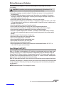
WARNING: Read the ENTIRE instruction manual to become familiar with the features of the product before
operating. Failure to operate the product correctly can result in damage to the product, personal property
and cause serious injury.
This is a sophisticated hobby product. It must be operated with caution and common sense and requires some
basic mechanical ability. Failure to operate this Product in a safe and responsible manner could result in injury or
damage to the product or other property. This product is not intended for use by children without direct adult su-
pervision. Do not attempt disassembly, use with incompatible components or augment product in any way without
the approval of Horizon Hobby, Inc. This manual contains instructions for safety, operation and maintenance. It is
essential to read and follow all the instructions and warnings in the manual, prior to assembly, setup or use, in
order to operate correctly and avoid damage or serious injury.
Age Recommendation: Not for children under 14 years. This is not a toy.
The following terms are used throughout the product literature to indicate various levels of potential harm when
operating this product:
NOTICE: Procedures, which if not properly followed, create a possibility of physical property damage AND a little
or no possibility of injury.
CAUTION: Procedures, which if not properly followed, create the probability of physical property damage AND a
possibility of serious injury.
WARNING: Procedures, which if not properly followed, create the probability of property damage, collateral
damage, and serious injury OR create a high probability of superficial injury.
Additional Safety Precautions and Warnings
• Alwayskeepasafedistanceinalldirectionsaroundyourmodeltoavoidcollisionsorinjury.Thismodeliscon-
trolled by a radio signal subject to interference from many sources outside your control. Interference can cause
momentary loss of control.
• Alwaysoperateyourmodelinopenspacesawayfromfull-sizevehicles,trafcandpeople.
• Alwayscarefullyfollowthedirectionsandwarningsforthisandanyoptionalsupportequipment(chargers,
rechargeablebatterypacks,etc.).
• Alwayskeepallchemicals,smallpartsandanythingelectricaloutofthereachofchildren.
• Alwaysavoidwaterexposuretoallequipmentnotspecicallydesignedandprotectedforthispurpose.Moisture
causes damage to electronics.
• Neverplaceanyportionofthemodelinyourmouthasitcouldcauseseriousinjuryorevendeath.
• Neveroperateyourmodelwithlowtransmitterbatteries.
NOTICE
All instructions, warranties and other collateral documents are subject to change at the sole discretion of
HorizonHobby,Inc.Forup-to-dateproductliterature,visithorizonhobby.comandclickonthesupporttabforthis
product.
Meaning of Special Language

3EN
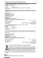
Troubleshooting
If you encounter any difficulties while charging, setting up, testing functions or flying your Blade mCX2,
see page 17 to contact the appropriate Horizon Product Support office.
Specifications
Fuselage Length ............7.9in(200mm)
Height ....................4.7in(120mm)
MainRotorDiameter .........7.5in(190mm)
Weight with Battery .........1.0oz(28g)
MainMotors ...............Microcoreless(2installed)
Battery ...................1-Cell3.7V150mAhLiPo(included)
Charger ..................1-Cell3.7VDCLiPo(included)
Transmitter ................MLP4DSM2.4GHzDSM4-channel(RTF Only)
On-Board Electronics ........5-in-1receiver/servos/mixer/ESCs/gyro(installed)
Table of Contents
Troubleshooting ................................................................3
Specifications ..................................................................3
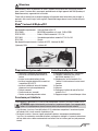
Blade® mCX2 Contents ...........................................................4
First Flight Preparation ...........................................................4
FlyingChecklist .................................................................4
BatteryWarningsandGuidelines ....................................................5
LowVoltageCutoff(LVC) ..........................................................5
Battery Charging ................................................................ 6
InstallingtheTransmitterBatteries(RTFONLY) .........................................6
Installing the Flight Battery ........................................................7
Transmitter and Receiver Binding ...................................................7
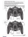
Transmitter Control Identification. . . . . . . . . . . . . . . . . . . . . . . . . . . . . . . . . . . . . . . . . . . . . . . . . . . . 9
Control Test ...................................................................10
Channel 5 Information ...........................................................12
5-in-1ControlUnitDescription,ArmingandMotorControlTest ............................12
Understanding the Primary Flight Controls ...........................................14
Dual Rates ...................................................................15
Choosing a Flying Area ..........................................................15
Flying the Blade mCX2 ..........................................................15
Advanced Swashplate Settings ....................................................16
TroubleshootingGuide. . . . . . . . . . . . . . . . . . . . . . . . . . . . . . . . . . . . . . . . . . . . . . . . . . . . . . . . . . . 17
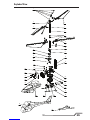
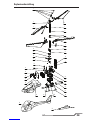
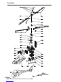
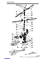
ExplodedViewPartsListing .......................................................18
ExplodedView .................................................................19
Replacement Parts List ..........................................................20
Option Parts ..................................................................20
Limited Warranty ...............................................................22
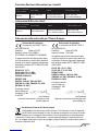
Warranty and Service Contact Information. . . . . . . . . . . . . . . . . . . . . . . . . . . . . . . . . . . . . . . . . . . . 23
Customer Service Information ..................................................... 23
Compliance Information for the European Union .......................................24

4
EN
Warning
An RC helicopter is not a toy! If misused, it can cause serious bodily harm and damage to property. Fly
onlyinopenareas,preferablyatAMA(AcademyofModelAeronautics)approvedyingsites,following
all instructions.
Keep items that can get entangled in the rotor blades away from the main and tail blades, including
looseclothing,pencilsandscrewdrivers.Especiallykeepyourhandsawayfromtherotorblades.
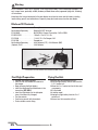
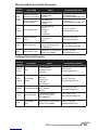
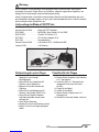
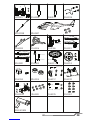
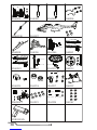
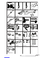
Blade® mCX2 Contents
Item Description
Not Available Separately ......Blade mCX2 RTF Airframe
EFLH1064B. . . . . . . . . . . . . . . . MLP4DSM4-ChannelTransmitter,2.4GHzDSMX
EFLB1501S25 ..............150mAh1-Cell3.7VLi-Po
EFLC1000 .................1-Cell3.7VLi-PoCharger,0.3A
EFLH1209 .................Screwdriver
Not Available Separately ......8AABatteries(RTF),4AABatteries(BNF)
(Optional)FUG4 .............4 AA Batteries
First Flight Preparation
• Remove and inspect contents
• Install four of the included AA batteries in
the charger
• Begin charging the flight battery
• Install the remaining four AA batteries in the
transmitter (RTF ONLY)
• Install the flight battery in the helicopter
(onceithasbeenfullycharged)
• Test the controls
• Familiarize yourself with the controls
• Find a suitable area for flying
Flying Checklist
❏Always turn the transmitter on first
❏ Plug the flight battery into the lead from the
5-in-1 control unit
❏ Allow the 5-in-1 control unit to initialize and
arm properly
❏Fly the model
❏Land the model
❏ Unplug the flight battery from the 5-in-1
control unit
❏Always turn the transmitter off last
*Transmitter and 4 AA Batteries not included with BNF Version

5EN
Battery Warnings and Guidelines
Theincludedbatterycharger(EFLC1000)hasbeendesignedtosafelychargetheincluded
Li-Po battery.
CAUTION:Allinstructionsandwarningsmustbefollowedexactly.MishandlingofLi-Po
batteries can result in a fire, personal injury, and/or property damage.
•Byhandling,chargingorusingtheincludedLi-Pobattery,youassumeallrisksassociatedwith
lithium batteries.
•Ifatanytimethebatterybeginstoballoonorswell,discontinueuseimmediately.Ifchargingor
discharging, discontinue and disconnect. Continuing to use, charge or discharge a battery that is
ballooning or swelling can result in fire.
•Alwaysstorethebatteryatroomtemperatureinadryareaforbestresults.
•Alwaystransportortemporarilystorethebatteryinatemperaturerangeof40–120ºF(4.44–48.88º
C).Donotstorebatteryoraircraftinacarordirectsunlight.Ifstoredinahotcar,thebatterycanbe
damaged or even catch fire.
•Alwayschargebatteriesawayfromammablematerials.
•Alwaysinspectthebatterybeforechargingandneverchargedamagedbatteries.
•Alwaysdisconnectthebatteryaftercharging,andletthechargercoolbetweencharges.
•Alwaysconstantlymonitorthetemperatureofthebatterypackwhilecharging.
•ONLYUSEACHARGERSPECIFICALLYDESIGNEDTOCHARGELI-POBATTERIES.Failuretocharge
the battery with a compatible charger may cause fire resulting in personal injury and/or property
damage.
•NeverdischargeLi-Pocellstobelow3Vunderload.
•Nevercoverwarninglabelswithhookandloopstrips.
•Neverleavechargingbatteriesunattended.
•Neverchargebatteriesoutsiderecommendedlevels.
•Neverattempttodismantleoralterthecharger.
•Neverallowminorstochargebatterypacks.
•Neverchargebatteriesinextremelyhotorcoldplaces(recommendedbetween40–120°For
4.44–48.88°C)orplaceindirectsunlight.
Low Voltage Cuto (LVC)
When a Li-Po battery is discharged below 3V, the battery may be damaged and may no longer accept
a charge. The mCX2’s 5-in-1 control unit protects the flight battery from over-discharge using Low
VoltageCutoff(LVC).Beforethebatterychargedecreasestoomuch,LVCremovespowersupplyfrom
themotor.PowertothemotordecreasesandtheLEDonthe5-in-1controlunitblinks,showingsome
battery power is reserved for flight control and safe landing.
When the motor power decreases, please land the aircraft immediately and recharge the flight battery.
DisconnectandremovetheLi-Pobatteryfromtheaircraftafterusetopreventtrickledischarge.Before
storage,chargetheLi-Pobatterytofullcapacity.Duringstoragemakesurethebatterychargedoes
not go below 3V.
NOTICE: Repeated flying to LVC will damage the battery.

6
EN
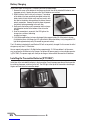
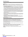
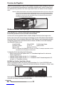
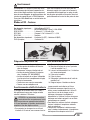
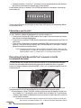
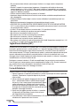
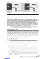
Battery Charging
Follow these steps to charge the Li-Po battery with the included charger:
1. Remove the cover on the bottom of the charger and install four of the included AA batteries, not-
ing proper polarity. Replace the cover after the AA batteries are installed.
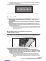
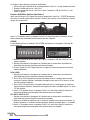
2. Slide the battery into the slot on the charger. The endcap
of the battery has been specifically designed to allow the
batterytobeslidintothesloteasilyoneway(usuallywith
thelabelonthebatteryfacingoutward)topreventreverse
polarityconnection.However,checkforproperalignment
andpolaritybeforeproceedingtothenextstep.
3.Gentlypressthebatteryanditsconnectorintothecharge
jack/connectorlocatedatthebottomoftheslotonthe
charger.
4. Once the connection is successful, the LED light on the
charger turns solid red, indicating
charging has begun.
5.Afullydischargedbattery(notover-discharged)takesapproximately30–40minutestocharge.
Asthebatterynearsfullcharge,theLEDlightwillblink.WhenthebatteryisfullychargedtheLED
lightblinksapproximatelyevery20secondsorgoesoutentirely.
The Li-Po battery included with your Blade mCX2 will arrive partially charged. For this reason the initial
chargemayonlytake15–20minutes.
YoucanexpecttochargetheLi-Poightbatteryapproximately15–20timesbeforeitwillbeneces-
sary to replace the AA batteries in the charger. An optional 6V power supply is also available separate-
ly(EFLC1005).ThispowersupplywillallowyoutochargeathomewithouttheneedforAAbatteries.
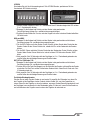
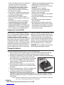
Installing the Transmitter Batteries (RTF ONLY)
InstallfouroftheincludedAAbatteriesinthetransmitter.Checkforproperoperationofthetransmitter
byswitchingthepowerswitchon(totheleft).TheLEDlightatthetopofthetransmittershouldbegin
to glow solid red while the transmitter beeps.

7EN
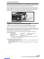
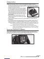
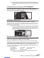
Installing the Flight Battery
Once the Li-Po battery is fully charged, you can install it in the helicopter. This is done by sliding it into
the battery mounting supports/slots just below the main gears. Slide the battery into the slots with the
labelfacingdownwardandtheconnectororientedtowardthebackofthehelicopter.
Be sure to slide the battery into the slots until the endcap of the battery comes into contact with the
rear battery support. This allows you to achieve the correct center of gravity for the best overall flight
performance.However,besurethebatteryisnotpushedfarenoughforwardthatitmakescontact
with the servo gears, as this could cause damage to the gears and a potential crash.
Transmitter and Receiver Binding
The Blade mCX2 RTF comes bound to the MLP4DSM transmitter included.
The BNF version requires you to bind to your own compatible DSMX Aircraft Transmitter.
To bind or re-bind your mCX2 to your chosen transmitter please follow the directions below:
BindingistheprocessofprogrammingthereceiverofthecontrolunittorecognizetheGUID(Globally
UniqueIdentier)codeofasinglespecictransmitter.Youneedto‘bind’yourchosenSpektrumDSMX
technology equipped aircraft transmitter to the receiver for proper operation.
FollowingaresomeoftheSpektrumDSMX-equippedtransmittersandmodulesthatbindtothe
receiver of your Blade mCX2.
E-iteMLP4DSM E-iteLP5DSM ParkZoneVaporTransmitter
PKZEmber2Transmitter JR12X2.4 SpektrumDX5e
SpektrumDX6i SpektrumDX7/DX7se
Note:TheSpektrumDX6(SPM2460)isequippedwithDSM(notDSMX)technologyandisnotcompat-
ible with the receiver of the Blade mCX2.
The following steps outline the binding process:
• Makesuretheightbatteryisdisconnectedfromthe5-in-1unitandthetransmitteristurnedoff.
• Plug the flight battery into the 5-in-1 unit.
• Plug the flight battery into the 5-in-1 unit. After 5 seconds the LED on the 5-in1 unit will begin
flashing.

8
EN
MLP4DSM and ParkZone Vapor/Ember 2 Transmitters
AfterverifyingtheLEDisashingonthereceiver/5-in-1,PUSHdirectlydownontheleft-handstick
whileswitchingthetransmitteron(youwillfeela‘click’whenyoupushinontheendofthestick).
Afterapproximately5–10secondsthereceiver/5-in-1shouldbeboundtothetransmitterandyou
should now have full control and function.
LP5DSM
IfyoudecidetouseanE-iteLP5DSMtransmitter,pleasepositionyourchannelreversaldipswitches
as follows.
1. Plug the flight battery into the 5-in-1 unit. After 5 seconds the LED on the 5-in-1 unit will
begin flashing.
2.Movethesticksandswitchesonthetransmittertothedesiredfailsafepositions(lowthrottleand
neutralcontrolpositions).
3. Turn the transmitter on. The red LED located under the door on the bottom left front of the trans-
mitterwillblinkrapidly.
DX5e and DX6i
1.Movethesticksandswitchesonthetransmittertothedesiredfailsafepositions(lowthrottleand
neutralcontrolpositions).
2. For the DX5e: Pull and hold the Trainer Switch on the transmitter while turning the transmitter on.
Release the trainer switch once the LEDs on the front of the transmitter flash.
3. For the DX6i: Pull and hold the Trainer Switch on the transmitter while turning the transmitter on.
Release the trainer switch once “BIND” Flashes on the LCD screen of the transmitter.
4.Afterapproximately5–10secondsthereceiver/5-in-1shouldbeboundtothetransmitterandyou
should have full control and function.
DX7, DX7se, X9303, or 12X:
1.Movethesticksandswitchesonthetransmittertothedesiredfailsafepositions(lowthrottleand
neutralcontrolpositions)
2.Pressthebindbuttononthebackofthetransmitterwhileturningthetransmitteron.Thebind
buttononthebackofthetransmitterwillash.Releasethebuttonafter2–3seconds.
3.Afterapproximately5-10secondsthereceiver/5-in-1shouldbeboundtothetransmitterandyou
should now have full control and function.
Additional Binding Information
Prior to each flight, power on your transmitter and wait about five seconds before you plug the flight
battery into the receiver. This allows time for the transmitter to scan and secure two open frequencies.
Ifyouplugtheightbatteryintooquicklyandmissthelink,thereceivermayinadvertentlyenterbind
mode. If this occurs leave the transmitter on, then disconnect and reconnect the flight battery.


10
EN
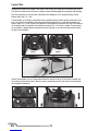
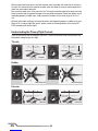
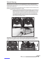
Control Test
Although each Blade mCX2 model is test flown at the factory, you should test the controls prior to the
rstighttoensurenoneoftheservos,linkagesorpartsweredamagedduringshippingandhandling.
Turnthetransmitteronrstandlowerthethrottlestickcompletely.Then,plugthebatteryintothe
battery lead of the 5-in-1 unit.
Theconnectorsonthebatteryandbatteryleadarekeyedtopreventreversepolarityconnection.How-
ever, if you force them together in the wrong orientation/wrong polarity it is possible to damage the
battery and/or 5-in-1 unit. To help further prevent a reverse polarity connection, one side of the endcap
on the battery and the connector on the battery lead of the 5-in-1 unit have a red dot. The connectors
areorientedforaproperpolarityconnectionwhenthereddotsareonthesameside(usuallytoward
thetopofthehelicopter).
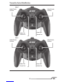
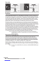
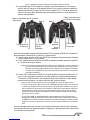
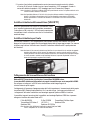
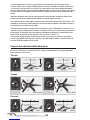
Mode1
Mode2
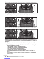
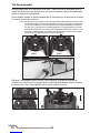
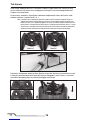
Positionthehelicoptertoviewitfrombehind.Movetheelevatorstickonthetransmitterforwardand
afttocheckelevatorpitchcontrol.Whenthestickispushedforward,theright-handservoshouldpull
the swashplate downward.
M2
M1

11 EN
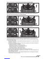
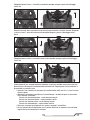
Withthestickpulledback,theright-handservoshouldpushtheswashplateupward.
M2
M1
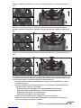
Movetheright-handstickleftandrighttocheckaileronrollcontrol.Whenthestickispushedtothe
left, the left-hand servo should pull the swashplate downward.
M2
M1
Withthestickpushedright,theleft-handservoshouldpushtheswashplateupward.
M2
M1
If at any time during the test the controls respond in the opposite direction, it may be necessary to
reverse/change the direction of operation of the flight controls. Follow these steps to change the direc-
tion the various flight controls:
• Be certain that the battery is disconnected from the battery lead of the 5-in-1 control unit and the
transmitter is turned off.
• Pushdownontheappropriatedigitaltrimbuttononthetransmitterforthecontrolyouwouldlike
tochangethedirectionof.Forexample:
Top elevator trim button—elevator channel normal
Bottom elevator trim button—elevator channel reversed
Left aileron trim button—aileron channel normal
Right aileron trim button—aileron channel reversed
• Continue to hold the appropriate trim button while turning the transmitter on.
• Holdthedigitaltrimbuttondownforapproximatelyveseconds,untilaseriesofbeeps/tonesare
heard confirming the selection.
• Connect the battery to the 5-in-1 and complete the flight control test, confirming that all controls
are operating in the correct directions.

12
EN
IfyoudecidetouseanE-iteLP5DSMtransmitter,pleasepositionyourchannelreversaldipswitches
as follows:
If you’ve confirmed proper control operation of your Blade mCX2, unplug the flight battery.
Channel 5 Information
Channel 5 affects rate settings of the 5-in-1 Control Unit.
• IfusingthestockMLP4DSMTransmitter,pleasereadPage21ofthismanualforDualRate
information.
• IfusinganLP5DSMTransmitter,pleaseturntheChannel5knobclockwise
completely.
• IfusinganyotherDSMXcompatibletransmitter,pleaseensureChannel5issettodefaultservo
reversalandtheswitchorknobissettoapositionthatallowsfulltravelcontrol.
Note:Thiscaneasilybetestedbyinducingfullcyclic(Aileron/Elevator)inputandmovingtheswitchor
knob.There’sapproximately10–15%lessservotraveldependingonwhatpositionChannel5isin.
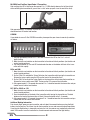
5-in-1 Control Unit Description, Arming and Motor Control Test
The unique Control Unit installed on your Blade mCX2 is a lightweight combination of main motor
electronicspeedcontrols,mixer,gyro,servosandSpektrumDSMXcompatiblereceiver.The5-in-1unit
is also equipped with a status indicator LED.
Thefollowingchecklistcontainsthestepstoensureproperarmingandoperationofthecontrolunit,as
well as proper motor response:
❏BeforeeachightALWAYSturnthetransmitteronbeforeconnectingtheightbatterytothe
5-in-1 unit. Never connect the flight battery to the 5-in-1 unit before powering the transmitter on
first. After each flight, always disconnect the flight battery from the 5-in-1 unit before powering
the transmitter off.
Note: the only time you should connect the flight battery to the 5-in-1 unit before powering the
transmitter on is when you are binding the receiver of the 5-in-1 unit to the transmitter. Please see the
Transmitter and Receiver Binding section of this manual for more information.
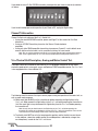
❏ThethrottlestickMUSTbesetinthelowestpossibleposition,andthethrottletrimmustbeset
tothemiddleoralowerthanmiddleposition(themiddlepositionisindicatedbyalongerthan
usualbeep/tone),inorderforthe5-in-1unittoarm.

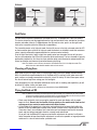
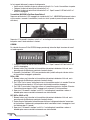
13 EN
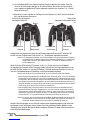
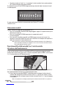
If this is the first test flight, or a test flight following repairs, you should also center the rudder,
aileron and elevator trims.
Mode1Mode2
Setthrottlesticktolowestposition.
Rudder Trim
Throttle Trim
Aileron Trim
Elevator Trim
Rudder Trim
Elevator Trim
Aileron Trim
Throttle Trim
Setthrottlesticktolowestposition.
After confirming that the transmitter has been turned on and that the LED is glowing solid RED, it is
now safe to connect the flight battery to the 5-in-1 unit.
❏ With the transmitter turned on and the LED glowing solid BLUE, it is now safe to connect the
flight battery to the 5-in-1 unit.
❏ With battery power applied to the 5-in-1 unit, the status indicator LED should glow solid RED
within a few seconds.
Note:Itisextremelyimportantthatyoudonotmove,swayorpretendtoythehelicopteroncethe
flight battery is connected because the initialization process and calibration of the gyro has
begun. If you do move the helicopter before the LED is solid RED, disconnect the flight battery
from the 5-in-1 unit and repeat the initialization process.
❏ When the status LED becomes solid RED, the control unit is initialized and ready for flight. Also,
aslongasyousetthethrottlestickandtrimtothecorrectpositionsduringtheinitialization
process, the ESCs/motors will now be armed. Use caution as both rotor blades will now spin with
throttlestickinput.
Note: If the status LED does not become solid RED, please review the following:
•IfafterBLUEstatusLEDbecomessolid,butyouhavenocontrolofthemotors,youhaveapositive
RadioFrequency(RF)linkbetweenthetransmitterandreceiver,butthethrottlestickandthrottletrim
maynotbesettothecorrectpositions.Checkthatthethrottlestickisinthelowestpossibleposition,
and the throttle trim is set to the middle or a lower than the middle position. If you now have control
ofthemotors,proceedtothenextstepofthechecklist.
•IfREDstatusLEDisoffcompletely,youdonothaveapositiveRFlinkbetweenthetransmitterand
receiver.CheckthatthetransmitterhasbeenpoweredonandtheLEDindicatoronthetransmitter
is glowing solid RED. If the transmitter is powered on and functioning properly, disconnect the flight
battery from the 5-in-1 unit, then reconnect it. The 5-in-1 unit should initialize and arm properly.
Once you place the helicopter in a safe area, free of obstructions, and are clear of the rotor blades, you
cansafelypowerupthemodeltocheckforproperoperationofthemotors.
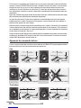
Advancethethrottlestickupwardslowly,justuntilbothrotorbladesbegintospin.DONOTattemptto
fly the helicopter at this time. Note the direction each of the rotor blades spins. When viewed from the
top,theuppermainrotorbladesshouldspincounterclockwiseandthelowermainrotorbladesshould
spinclockwise.Ifeithersetofrotorbladesisoperatinginthewrongdirection,disconnectthebattery
and reverse the polarity of the corresponding motor’s input power leads.
After confirming the rotor blades rotate in the correct direction, confirm that both rotor blades respond
properly to rudder control inputs.

14
EN
Withtherotorbladesspinningatalowlevelofpower,movetherudder(left-hand)stickallthewayto
the right. This should cause the speed of the upper main rotor blade to increase, and the speed of the
lower main rotor blade to decrease.
Next,movetherudderstickallthewaytotheleft.Thisshouldcausethespeedofthelowermainrotor
blade to increase and the speed of the upper main rotor blade to decrease. If both rotor blades are not
responding properly to rudder input, simply reverse the locations of their motor plugs on the 5-in-1
unit.
With both rotor blades rotating in the correct directions and responding properly to rudder inputs, your
Blade mCX2 is ready for flight. But you will need to review the following sections of the manual BE-
FORE proceeding with the first flight.
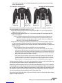
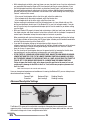
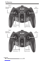
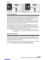
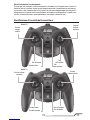
Understanding the Primary Flight Controls
IfyouarenotfamiliarwiththecontrolsofyourmCPX,takeafewminutestofamiliarizeyourselfwith
them before attempting your first flight.
Throttle
Rudder
Elevator
Ascend Decend
NoseYawsLeft NoseYawsRight
Forward Backward

15 EN
Dual Rates
TheMLP4DSMtransmitterincludedwithyourBlademCX2RTFisequippedwithadualratefeature.
This feature allows the pilot the toggle between the high and low control rates available for the aileron,
elevator and rudder channels. To toggle between the high and low rates, push in on the right-hand
stickonthetransmitter(whilethetransmitterispoweredon).
Thetransmittercomessetinhigh-ratemode.Youcantellyouareinthehigh-ratemodewhentheLED
onthetransmitterglowssolidred.Inhigh-ratemodethecontrolsareallowedtoreachtheirmaximum
values,typicallypreferredbyexperiencedpilotsformaximumcontrolauthority.
Pushtheright-handstickinwhileinhigh-ratemodetoenterlow-ratemode.Youcantellyouarein
thelow-ratemodewhentheLEDonthetransmitterblinkscontinuously.Thelow-ratemodeistypically
preferredby(andbestfor)rst-time,low-timeandotherpilotsmostinterestedinreducedcontrolthat
allows for smoother and more easily controlled hovering and flying.
Note: The throttle curve in the low rate mode is also different than it is in the high rate mode. This
makeslow-rate-modethrottlesmootherandeasiertocontrol.
Choosing a Flying Area
When ready for your first flight, select a relatively open indoor area free of people and obstructions.
WhileitispossibleforexperiencedpilotstoytheBlademCX2inrelativelysmallindoorareaswith
greatsuccess,westronglyrecommendanareawithatleast10-feetby10-feetofoorspaceandno
lessthan8-footceilingswhenmakingyourrstfewights.
Once you properly trim your helicopter and become familiar with its handling and capabilities, you will
be able to fly in other smaller, less open areas.
Note:TheBlademCX2isdesignedandintendedtobeownINDOORSONLY.
Flying the Blade mCX2
Note: In addition to reviewing the flight maneuvers outlined below, we recommend you watch Videos
located on the product page for the Blade mCX2 on www.horizonhobby.com to see many of these
maneuvers and adjustments performed by the helicopter and pilot.
• Slowlyraisethethrottlestick,increasingthespeedofthemainrotorbladesuntilthemodel
begins to lift off. Do not raise the throttle stick too quickly as the model could climb too fast
causing you to lose control or make contact with objects above.
• Liftthemodeloffthegroundjustafewinchesandconcentrateonbalancingthethrottlestick
positionsothatthemodelholdsasteadyhoveraltitude.Insomecasesitmaybebesttomake
a few short “hops” to an altitude of just a few inches until you become familiar with the control
inputs and trim settings required to maintain a steady hover and altitude.
As you will find, the Blade mCX2 requires minor throttle adjustments to maintain its altitude in
hover.Remembertokeepthesethrottleadjustmentsasminimalaspossibleaslargeadjustments
could result in a loss of control and/or a possible crash.
Aileron
Left Right

16
EN
• Whileattemptingtoestablishalow-levelhover,youcanalsochecktoseeifanytrimadjustments
arerequiredtohelpkeeptheBlademCX2fromconstantlydriftinginvariousdirections.Ifyou
find the helicopter constantly drifts without any directional control input, it will be best to land
themodelbeforemakinganyadjustmentstothetrimsettings.Additionaldetailsregardingthe
location and function of the trim buttons can be found in the “Understanding the Primary Flight
Controls” section of this manual.
- If the nose of the helicopter drifts to the left or right, adjust the rudder trim.
-Ifthehelicopterdriftsforwardorbackward,adjusttheelevatortrim.
- If the helicopter drifts to the left or right, adjust the aileron trim.
Continuemakingtrimadjustmentsuntilthehelicopterhoversatalowaltitudewithverylittle
drifting and directional control input. If the Blade mCX2 is your first helicopter model, it may be
besttohavethehelpofanexperiencedhelicopterpilottotrimthemodelforyoubeforemaking
your first flight.
• With your Blade mCX2 properly trimmed and maintaining a stable low-level hover, practice using
the rudder, elevator and aileron controls to familiarize yourself with the helicopter’s responses to
controlinputs.Remembertokeepthecontrolinputsasminimalaspossible.
When comfortable with low-level hovering, you can transition to hovering and flying the helicop-
ter at higher altitudes of three to four feet. At these higher altitudes you will become comfortable
with the flight characteristics of the Blade mCX2.
• If you feel the helicopter drifting out of control during flight, release all of the
controlsexceptforthrottle.Youwillneedthrottletomaintainaltitude,butbecauseoftheinherent
stabilityofthecoaxial,counter-rotatingbladedesign,theBlademCX2willreturntoastable
hover on its own, if space allows.
• Don’tbeafraidtosetthehelicopterdownonthegroundquicklybyloweringthethrottlewhen
approachingwallsorotherobstaclestohelppreventmainrotorbladestrikes.
• IN THE EVENT OF A CRASH OR ROTOR BLADE STRIKE, NO MATTER HOW MINOR OR MAJOR,
LOWER THE THROTTLE STICK TO THE LOWEST POSSIBLE POSITION AS QUICKLY AS POSSI-
BLE TO PREVENT DAMAGE TO THE ESCS OF THE 5-IN-1 UNIT. ALSO BE SURE THE THROTTLE
TRIM IS SET TO THE MIDDLE POSITION OR TO A LOWER THAN THE MIDDLE POSITION.
Failure to lower the throttle stick to the lowest possible position in the event of a crash
could result in damage to the ESCs in the 5-in-1 unit, which may require replacement of
the 5-in-1 unit.
Note: Crash damage is not covered under warranty.
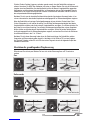
OnceyouhavegainedexperienceandcondenceinhoveringtheBlademCX2,youcanattemptmore
advanced maneuvers including:
ForwardFlight BackwardFlight SkiddingTakeoffs
Pirouettes SpotLandings SkiddingLandings
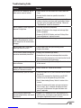
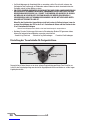
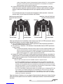
Advanced Swashplate Settings
Short Swashplate
Control Balls
Long Swashplate
Control Balls
The Blade mCX2 comes with an adjustable swashplate. Advanced pilots may benefit from a more
aggressivesetup.Toachieveamoreaggressivesetup,popoffthelowerrotorheadlinksandmove
them onto the longer set of inner swashplate control balls.

17 EN
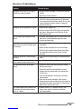
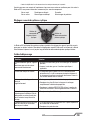
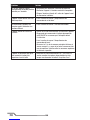
Troubleshooting Guide
Problem Solution
Aircraft will not “throttle up” but all
other controls seem to function.
•Lowerthrottlestickandthrottletrimtotheirlowestset-
tings.
•Reversethrottlechannelonspecictransmitterif
applicable.
Upperrotorhead/hubisbroken. •ReplacewithEFLH2412bycarefullyremovingthe(2)
screws in the lower main gear and transferring all unbro-
kenpartstothenewupperrotorhead/hub.Followthe
“ExplodedView”sectionofthemanual.
Aircraft appears to show significant
decrease in flight time.
•Rechargeightbatterycompletely.
•ReplaceAAbatteriesinthechargerandrechargeight
battery completely.
•ReplaceEFLB1501S25batteryandread“BatteryWarn-
ingsandGuidelines”sectionofmanual.
Charger light stays on after Li-Po
battery is disconnected or remains
onforlongerthan40minuteswhen
charging.
•ReplaceAAbatteriesinthecharger.
Aircraft hovers with a “toilet bowl”
effect type circle on its own.
•Loosenupperrotorhubybarretainingscrew.
•Replacerotorblades.
LED on Aircraft remains flashing and
cannot be controlled by transmitter.
•Unplug,thenreconnectightbattery.
•RebindAircrafttoyourdesiredcompatibletransmitter.
•Movetransmitter(poweredon)afewfeetfromtheAircraft
prior to reconnecting the flight battery.
Aircraft appears to drift towards a
certain direction.
•Read“UnderstandingthePrimaryFlightControls”section
of this manual.
Controls appear to be reversed after
binding to a different transmitter.
•Read“ControlTest”sectionofthismanual.
Aircraft constantly spins on its own. •Centertheruddertrimonyourtransmitterandre-initialize
the aircraft.
•Unplug,thenreconnecttheightbatteryandDONOT
move or sway the helicopter during initialization.
•Read“UnderstandingPrimaryControls”sectionofthis
manual.
•Loosen(2)screwsonthelowermaingearandensure
there is slight “play” in between the upper and lower
main gears. Lube between the upper and lower main
gears if applicable.
Aircraft does not function after
connecting flight battery and aircraft
smells burnt.
•Replace5-in-1board(EFLH2401)andensuretheRED
polaritymarksarefacingthesamedirectionwhencon-
necting the flight battery to the 5-in-1 board.

18
EN
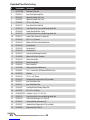
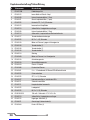
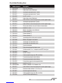
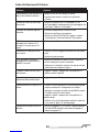
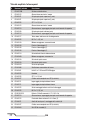
Exploded View Parts Listing
# Item Number Description
1 EFLH2219B Stabilizer Flybar Set
2 EFLH2412 Inner Shaft with Head/Hub
3 EFLH2421 UpperMainBladeSet(1pr)
4 EFLH2421 UpperMainBladeSet(1pr)
5 EFLH2225 ST1.2x5(2)Screw
6 EFLH2412 Inner Shaft with Head/Hub
7 EFLH2213 OuterShaft,MainGearandBushingHolderSet
8 EFLH2420 LowerMainBladeSet(1pair)
9 EFLH2213 OuterShaft,MainGearandBushingHolderSet
10 EFLH2217 LowerRotorHeadandLinkageSet
11 EFLH2225 M1.2x1.8(2)Screw
12 EFLH2410 MotorwithPinion,Counterclockwise
13 EFLH2416 Swashplate(1)
14 EFLH2416 Swashplate(1)
15 EFLH2416 Swashplate(1)
16 EFLH2214 Outer Shaft Retaining Collar Set
17 EFLH2409 MotorwithPinion,Clockwise
18 EFLH2418 Servo Pushrod Set
19 EFLH2418 Servo Pushrod Set
20 EFLH2424 MainFrameSet
21 EFLH1066 ReplacementServoMechanics
22 EFLH2401 5-in-1ControlUnit,RX/Servos/ESCs/Mxr/Gyro
23 EFLH2225 Washers
24 EFLH2225 ST1.2x5(2)Screw
25 EFLH2427 CompleteRedCanopywithLEDs(installed)
26 EFLH2211 InnerShaftMainGear
27 EFLH2211 InnerShaftMainGear
28 EFLH2222 LandingSkidandBatteryMountSet
29 EFLH2225 M1.2x2.5(2)Screw
30 EFLB1501S25 150mAh1-Cell3.7V14CLi-Po
31 EFLH2213 OuterShaft,MainGearandBushingHolderSet
32 EFLH2215 OuterShaftBearing3x6x2mm(2)
33 EFLH3021 CanopyMountingGrommets(8)
34 EFLH2427 CompleteRedCanopywithLEDs(installed)
35 EFLH2404 ReplacementLEDSet(4)


20
EN
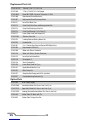
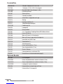
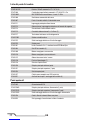
Replacement Parts List
EFLB1501S25 150mAh1-Cell3.7V14CLi-Po
EFLC1000 1-Cell3.7V0.3ADCLi-PoCharger
EFLH1064B BladeMLP4DSM4-channelTransmitter,2.4GHz
EFLH1066 ReplacementServoMechanics
EFLH1067 Replacement Servo Retaining Collars
EFLH2211 InnerShaftMainGear
EFLH2213 OuterShaft,MainGearandBushingHolderSet
EFLH2214 Outer Shaft Retaining Collar Set
EFLH2215 OuterShaftBearing3x6x2mm(2)
EFLH2217 LowerRotorHeadandLinkageSet
EFLH2219B Stabilizer Flybar Set
EFLH2222 LandingSkidandBatteryMountSet
EFLH2225 Hardware Set
EFLH2401 5-in-1ControlUnit,Receiver/Servos/ESCs/Mixer/Gyro
EFLH2404 ReplacementLEDSet(4)
EFLH2409 MotorwithPinion,Clockwise
EFLH2410 MotorwithPinion,Counter-Clockwise
EFLH2412 Inner Shaft with Head/Hub
EFLH2416 Swashplate(1)
EFLH2418 Servo Pushrod Set
EFLH2420 LowerMainBladeSet(1pr)
EFLH2421 UpperMainBladeSet(1pr)
EFLH2424 MainFrameSet
EFLH2427 CompleteRedCanopywithLEDs(Installed)
EFLH3021 CanopyMountingGrommets(8)
Option Parts
EFLC1005 6V AC Power Supply
EFLH2220GL LowerMainBladeSet,Glow-in-the-Dark(1pr)
EFLH2221GL UpperMainBladeSet,Glow-in-the-Dark(1pr)
EFLH2222GL LandingSkidandBatteryMountSet,Glow-in-the-Dark
EFLH2428 Carbon Fiber Tail Boom with Fin
EFLH3023 CarbonFiberTrainingGearSet
La pagina si sta caricando...
La pagina si sta caricando...
La pagina si sta caricando...
La pagina si sta caricando...
La pagina si sta caricando...
La pagina si sta caricando...
La pagina si sta caricando...
La pagina si sta caricando...
La pagina si sta caricando...
La pagina si sta caricando...
La pagina si sta caricando...
La pagina si sta caricando...
La pagina si sta caricando...
La pagina si sta caricando...
La pagina si sta caricando...
La pagina si sta caricando...
La pagina si sta caricando...
La pagina si sta caricando...
La pagina si sta caricando...
La pagina si sta caricando...
La pagina si sta caricando...
La pagina si sta caricando...
La pagina si sta caricando...
La pagina si sta caricando...
La pagina si sta caricando...
La pagina si sta caricando...
La pagina si sta caricando...
La pagina si sta caricando...
La pagina si sta caricando...
La pagina si sta caricando...
La pagina si sta caricando...
La pagina si sta caricando...
La pagina si sta caricando...
La pagina si sta caricando...
La pagina si sta caricando...
La pagina si sta caricando...
La pagina si sta caricando...
La pagina si sta caricando...
La pagina si sta caricando...
La pagina si sta caricando...
La pagina si sta caricando...
La pagina si sta caricando...
La pagina si sta caricando...
La pagina si sta caricando...
La pagina si sta caricando...
La pagina si sta caricando...
La pagina si sta caricando...
La pagina si sta caricando...
La pagina si sta caricando...
La pagina si sta caricando...
La pagina si sta caricando...
La pagina si sta caricando...
La pagina si sta caricando...
La pagina si sta caricando...
La pagina si sta caricando...
La pagina si sta caricando...
La pagina si sta caricando...
La pagina si sta caricando...
La pagina si sta caricando...
La pagina si sta caricando...
La pagina si sta caricando...
La pagina si sta caricando...
La pagina si sta caricando...
La pagina si sta caricando...
La pagina si sta caricando...
La pagina si sta caricando...
La pagina si sta caricando...
La pagina si sta caricando...
La pagina si sta caricando...
La pagina si sta caricando...
La pagina si sta caricando...
La pagina si sta caricando...
-
 1
1
-
 2
2
-
 3
3
-
 4
4
-
 5
5
-
 6
6
-
 7
7
-
 8
8
-
 9
9
-
 10
10
-
 11
11
-
 12
12
-
 13
13
-
 14
14
-
 15
15
-
 16
16
-
 17
17
-
 18
18
-
 19
19
-
 20
20
-
 21
21
-
 22
22
-
 23
23
-
 24
24
-
 25
25
-
 26
26
-
 27
27
-
 28
28
-
 29
29
-
 30
30
-
 31
31
-
 32
32
-
 33
33
-
 34
34
-
 35
35
-
 36
36
-
 37
37
-
 38
38
-
 39
39
-
 40
40
-
 41
41
-
 42
42
-
 43
43
-
 44
44
-
 45
45
-
 46
46
-
 47
47
-
 48
48
-
 49
49
-
 50
50
-
 51
51
-
 52
52
-
 53
53
-
 54
54
-
 55
55
-
 56
56
-
 57
57
-
 58
58
-
 59
59
-
 60
60
-
 61
61
-
 62
62
-
 63
63
-
 64
64
-
 65
65
-
 66
66
-
 67
67
-
 68
68
-
 69
69
-
 70
70
-
 71
71
-
 72
72
-
 73
73
-
 74
74
-
 75
75
-
 76
76
-
 77
77
-
 78
78
-
 79
79
-
 80
80
-
 81
81
-
 82
82
-
 83
83
-
 84
84
-
 85
85
-
 86
86
-
 87
87
-
 88
88
-
 89
89
-
 90
90
-
 91
91
-
 92
92


Blade Blade mCX2 Manuale del proprietario
- Categoria
- Giocattoli telecomandati
- Tipo
- Manuale del proprietario
in altre lingue
- English: Blade Blade mCX2 Owner's manual
- français: Blade Blade mCX2 Le manuel du propriétaire
- Deutsch: Blade Blade mCX2 Bedienungsanleitung