La pagina si sta caricando...

GB
F
D
2
I
1 GENERAL
1.1 GENERAL
INFORMATION
1.2 SYMBOLS
1.3 Electrical characteristics
table
2 MOUNTING
INSTRUCTIONS
2.1 OPENING SIDES
2.2 MOUNTING, SETTING
AND CONNECTION OF
ON-BOARD MACHINE
CONTROL PANELS
B0642, B0643
2.1.1 Mounting
2.2.2 Programming
2.2.3 Mounting air
temperature probe (only
for model B0642)
2.2.4 Setting auxiliary
functions dip-switches A
and B
2.2.5 Setting CP presence
contact input
2.2.6 B0642 connections
2.2.7 B0643 connections
2.3 MOUNTING B0373
2.4 CONNECTIONS
2.4.1 CP presence contact
input connection
3 USE
3.1 ELECTRONIC
CONTROL WITH LED
BAR ON-BOARD THE
MACHINE (B0642)
3.1.1 General switching on
3.1.2 MODE button
3.1.3 Activation
3.1.4 Manual heating/cooling
selection
3.1.5 Stand By
3.1.6 Temperature selection
3.1.7 LED indications
3.1.8 Error signals
3.1.9 Automatic functioning
3.1.10 Silent functioning
3.1.11 Night functioning
1 GENERALITES
1.1 INFORMATIONS
GENERALES
1.2 SYMBOLES
1.3 Tableau caractéristiques
électriques
2 INSTRUCTIONS DE
MONTAGE
2.1 OUVERTURE FLANCS
2.2 MONTAGE,
PARAMETRAGE
ET CONNEXIONS
DES PUPITRES DE
COMMANDE SUR
LA MACHINE B0642,
B0643
2.1.1 Montage
2.2.2 Programmation
2.2.3 Montage du capteur
de température air
(uniquement pour modèle
B0642)
2.2.4 Paramétrage des
fonctions auxiliaires dip-
switch A et B
2.2.5 Paramétrage entrée
contact présence CP
2.2.6 Connexions B0642
2.2.7 Connexions B0643
2.3 MONTAGE B0373
2.4 BRANCHEMENTS
2.4.1 Connexion entrée
contact présence CP
3 UTILISATION
3.1 COMMANDE
ELECTRONIQUE AVEC
BARRE A DIODES SUR
MACHINE (B0642)
3.1.1 Allumage général
3.1.2 Touche MODE
3.1.3 Activation
3.1.4 Sélection manuelle
chauffage/
refroidissement.
3.1.5 Veille
3.1.6 Sélection de la
température
3.1.7 Indication des diodes
3.1.8 Signaux d’erreur
3.1.9 Fonctionnement
automatique
3.1.10 Fonctionnement
silencieux
3.1.11 Fonctionnement
nocturne
6
6
8
8
10
10
10
12
14
16
18
18
20
22
24
26
28
30
32
32
32
32
32
34
34
34
36
38
40
40
1 ALLGEMEINES
1.1 ALLGEMEINE
INFORMATIONEN
1.2 SYMBOLGEBUNG
1.3 Tabelle der
elektrischen
Eigenschaften
2 MONTAGEANLEITUNG
2.1 ÖFFNUNG DER
SEITEN
2.2 MONTAGE, SETUP UND
PROGRAMMIERUNG
DER BEDIENTAFEL AN
BORD DER MASCHINE
B642, B643
2.1.1 Montage
2.2.2 Programmierung
2.2.3 Montage der
Lufttemperatursonde
(nur für Modell B0642)
2.2.4 Setup der
Hilfsfunktionen Dip-
Switch A und B
2.2.5 Einstellung Eingang
Kontakt Vorhandensein
CP
2.2.6 Anschlüsse B0642
2.2.7 Anschlüsse B0643
2.3 MONTAGE B0373
2.4 ANSCHLÜSSE
2.4.1 Anschluss Eingang
Kontakt Vorhandensein
CP
3 BEDIENUNG
3.1 ELEKTRONISCHE
STEUERUNG MIT LED-
LEISTE AN BORD DER
MASCHINE (B0642)
3.1.1 Haupteinschaltung
3.1.2 MODE-Taste
3.1.3 Aktivierung
3.1.4 Manuelle Wahl
Heizung / Kühlung
3.1.5 Stand-by
3.1.6 Temperaturwahl
3.1.7 Angabe der Led
3.1.8 Fehlermeldung
3.1.9 Automatikbetrieb
3.1.10 Geräuscharmer
Betrieb
3.1.11 Nachtbetrieb
1 GENERALITA’
1.1 INFORMAZIONI
GENERALI
1.2 SIMBOLOGIA
1.3 Tabella caratteristiche
elettriche
2 ISTRUZIONI
MONTAGGIO
2.1 APERTURA FIANCHI
2.2 MONTAGGIO,
SETTAGGIO E
CONNESSIONI
PANNELLI DI
COMANDO A BORDO
MACCHINA B0642,
B0643
2.1.1 Montaggio
2.2.2 Programmazione
2.2.3 Montaggio sonda
temperatura aria (solo
per modello B0642)
2.2.4 Settaggio funzioni
ausiliarie dip-switch A
e B
2.2.5 Impostazione ingresso
contatto presenza CP
2.2.6 Connessioni B0642
2.2.7 Connessioni B0643
2.3 MONTAGGIO B0373
2.4 COLLEGAMENTI
2.4.1 Connessione ingresso
contatto presenza CP
3 USO
3.1 COMANDO
ELETTRONICO
CON BARRA LED A
BORDO MACCHINA
(B0642)
3.1.1 Accensione generale
3.1.2 Tasto MODE
3.1.3 Attivazione
3.1.4 Selezione manuale
riscaldamento/
raffrescamento
3.1.5 Stand By
3.1.6 Selezione della
temperatura
3.1.7 Indicazione dei led
3.1.8 Segnalazioni d’errore
3.1.9 Funzionamento
automatico
3.1.10 Funzionamento
silenzioso
3.1.11 Funzionamento
notturno

GB
F
D
4
I
3.1.12 Funzionamento alla
massima velocità di
ventilazione
3.1.13 Segnalazioneltro
sporco
3.1.14 Disattivazione
3.1.15 Spegnimento per
lunghi periodi
3.2 CONTROLLO
REMOTO A MURO
BROADCAST (B0373)
3.2.1 Accensione generale
3.2.2 Tasto MODE
3.2.3 Attivazione
3.2.4 Selezione manuale
riscaldamento/
raffrescamento
3.2.5 Stand By
3.2.6 Selettore temperatura
3.2.7 Indicazione dei led
3.2.8 Funzionamento
automatico
3.2.9 Funzionamento
silenzioso
3.2.10 Funzionamento
notturno
3.2.11 Funzionamento alla
massima velocità di
ventilazione
3.2.12 Segnalazioneltro
sporco
3.2.13 Disattivazione
3.2.14 Spegnimento per
lunghi periodi
3.3 COMANDO
ELETTRONICO PER
REMOTIZZAZIONE
BROADCAST A
BORDO MACCHINA
(B0643)
3.1.12 Operation at
maximum ventilation
speed
3.1.13 Dirty lter signal
3.1.14 Deactivation
3.1.15 Shut-down for long
periods
3.2 BROADCAST WALL-
MOUNTED REMOTE
CONTROL (B0373)
3.2.1 General switching on
3.2.2 MODE button
3.2.3 Activation
3.2.4 Manual heating/cooling
selection
3.2.5 Stand By
3.2.6 Temperature selector
3.2.7 LED indications
3.2.8 Automatic functioning
3.2.9 Silent functioning
3.2.10 Night functioning
3.2.11 Operation at maximum
ventilation speed
3.2.12 Dirty lter signal
3.2.13 Deactivation
3.2.14 Shut-down for long
periods
3.3 ELECTRONIC
CONTROL FOR
BROADCAST
REMOTE CONTROL
ON-BOARD THE
MACHINE (B0643)
3.1.12 Fonctionnement à la
vitesse maximale de
ventilation
3.1.13 Indicationltre
encrassé
3.1.14 Désactivation
3.1.15 Extinction pendant de
longues périodes
3.2 CONTROLE A
DISTANCE MURAL
BROADCAST (B0373)
3.2.1 Allumage général
3.2.2 Touche MODE
3.2.3 Activation
3.2.4 Sélection manuelle
chauffage/
refroidissement.
3.2.5 Veille
3.2.6 Sélecteur de
température
3.2.7 Indication des diodes
3.2.8 Fonctionnement
automatique
3.2.9 Fonctionnement
silencieux
3.2.10 Fonctionnement
nocturne
3.2.11 Fonctionnement à la
vitesse maximale de
ventilation
3.2.12 Indicationltre
encrassé
3.2.13 Désactivation
3.2.14 Extinction pendant de
longues périodes
3.3 COMMANDE
ELECTRONIQUE
POUR COMMANDE
A DISTANCE
BROADCAST SUR
MACHINE (B0643)
42
42
42
42
44
46
46
46
46
48
48
48
50
52
52
54
54
54
54
56
3.1.12 Betrieb bei maximaler
Belüftungsgeschwindigkeit
3.1.13 Meldung Filter
verschmutzt
3.1.14 Deaktivierung
3.1.15 Ausschalten für lange
Zeiträume
3.2 FERNSTEUERUNG
AN DER WAND
BROADCAST (B0373)
3.2.1 Haupteinschaltung
3.2.2 MODE-Taste
3.2.3 Aktivierung
3.2.4 Manuelle Wahl
Kühlung / Heizung
3.2.5 Stand-by
3.2.6 Temperaturwähler
3.2.7 Angabe der Led
3.2.8 Automatikbetrieb
3.2.9 Geräuscharmer
Betrieb
3.2.10 Nachtbetrieb
3.2.11 Betrieb bei maximaler
Belüftungsgeschwindigkeit
3.2.12 Meldung Filter
verschmutzt
3.2.13 Deaktivierung
3.2.14 Ausschalten für lange
Zeiträume
3.3 ELEKTRONISCHE
STEUERUNG FÜR
FERNBETRIEB
BROADCAST
AN BORD DER
MASCHINE (B0643)

GB
F
D
6
I
1
GENERALITA’
INFORMAZIONI GENERALI
Il presente manuale è destinato
esclusivamente al tecnico
installatore qualificato ed
autorizzato, che dovrà essere
adeguatamente istruito ed in
possesso di tutti i requisiti
psicosici richiesti a norma
di legge.
Tutte le operazioni dovranno
essere eseguite con cura e a
regola d’arte, in conformità
delle norme di sicurezza sul
lavoro vigenti.
Dopo aver tolto l’imballo assicurarsi
dell'integrità e della completezza
del contenuto. In caso di non
rispondenza rivolgersi all'Agenzia
OLIMPIA SPLENDID che ha venduto
l'apparecchio.
È vietato modicare i dispositivi
di sicurezza o di regolazione
senza l’autorizzazione e le
indicazioni del costruttore
dell’apparecchio.
È vietato disperdere e lasciare
alla portata di bambini il materiale
dell'imballo in quanto può essere
potenziale fonte di pericolo.
Gli interventi di riparazione o
manutenzione devono essere
eseguiti dal Servizio Tecnico
di Assistenza o da personale
qualificato secondo quanto
previsto dal presente libretto.
Non modificare o manomettere
l’apparecchio in quanto si
possono creare situazioni di
pericolo ed il costruttore
dell’apparecchio non sarà
responsabile di eventuali danni
provocati.
SMALTIMENTO
Il simbolo sul prodotto o sulla
confezione indica che il prodotto
non deve essere considerato
comeunnormaleriutodome-
stico, ma deve essere portato nel
punto di raccolta appropriato per
il riciclaggio di apparecchiature
elettriche ed elettroniche.
Provvedendo a smaltire questo
prodotto in modo appropriato,
si contribuisce a evitare poten-
ziali conseguenze negative per
l’ambiente e per la salute, che
potrebbero derivare da uno smal-
timento inadeguato del prodotto.
Per informazioni più dettagliate
sul riciclaggio di questo prodotto,
contattare l’ufcio comunale, il
servizio locale di smaltimento
riutioilnegozioincuièstato
acquistato il prodotto.
Questa disposizione è valida
solamente negli Stati membri
dell’UE.
1
1.1
GENERAL
GENERAL INFORMATION
This manual is dedicated
exclusively for the qualied,
authorised installation
technician who must be
adequately trained and
possess all the necessary
psychophysical requirements
requested by law.
All the operations must be
performed with care and good
workmanship in compliance
with the safety at work
regulations in force.
After unpacking, make sure that all
the components are present. If not,
contact the OLIMPIA SPLENDID
agent who sold the appliance to you.
It is forbidden to modify the safety or
adjustment devices or adjust without
authorisation and indications of the
manufacturer.
It is forbidden to dispose of, or
leave in the reach of children, the
packaging materials which could
become a source of danger.
All repair or maintenance
interventions must be performed by
the technical service department or
by professionally qualied personnel
as foreseen in this booklet. Do not
modify or intervene on the appliance
as this could create dangerous
situations and the manufacturer will
not be responsible for any damage
caused.
DISPOSAL
This symbol on the product or its
packaging indicates that the
appliance cannot be treated as
normal domestic trash, but must be
handed in at a collection point for
recycling electric and electronic
appliances.
Your contribution to the correct
disposal of this product protects the
environment and the health of your
fellow men. Health and the
environment are endangered by
incorrect disposal.
Further information about the
recycling of this product can be
obtained from your local town hall,
your refuse collection service, or in
the store at which you bought the
product.
This regulation is valid only in EU
member states.
GENERALITES
INFORMATIONS GENERALES
Le présent manuel est destiné
exclusivement au technicien
installateur qualié et autorisé,
qui devra être correctement
formé et remplir toutes les
conditions psychophysiques
requises par la loi.
Toutes les opérations devront
être effectuées avec soin
et selon les règles de l'art,
conformément aux normes de
sécurité sur le lieu de travail
en vigueur.
Après avoir enlevé l'emballage, s'assurer
de l'intégrité et du caractère complet
du contenu. En cas de non conformité,
s'adresser à l'agence OLIMPIA
SPLENDID qui a vendu l'appareil.
Ilestdéfendudemodierlesdispositifsde
sécurité ou de réglage sans l'autorisation
et les indications du constructeur de
l'appareil.
Il est défendu de jeter dans la nature
ou de laisser à la portée des enfants le
matériau d'emballage car il peut être une
source potentielle de danger.
Les interventions de réparation ou
d'entretien doivent être effectuées par le
Service technique d'assistance ou par du
personnelqualiéselonlesindications
duprésentmanuel.Nepasmodierou
altérer l'appareil car cela pourrait créer
des situations de danger et le fabricant
de l'appareil n'est pas responsable des
éventuels dommages provoqués.
ELIMINATION
Ce symbole apposé sur le produit ou
son emballage indique que ce produit
ne doit pas être jeté au titre des
ordures ménagères normales, mais
doit être remis à un centre de collecte
pour le recyclage des appareils
électriques et électroniques.
En contribuant à une élimination
correcte de ce produit, vous protégez
l'environnement et la santé d'autrui.
L'environnement et la santé sont mis
en danger par une élimination
incorrecte du produit.
Pour toutes informations
complémentaires concernant le
recyclage de ce produit, adressezvous
à votre municipalité, votre
service des ordures ou au magasin
où vous avez acheté le produit.
Cette consigne n'est valable que pour
les états membres de l'UE.
ALLGEMEINES
ALLGEMEINE
INFORMATIONEN
Dieses Handbuch ist
zur ausschließlichen
Benutzung durch den
autorisierten Fachtechniker
bestimmt, der angemessen
eingewiesen zu sein und die
gesetzlich vorgeschriebenen
psychophysischen
Voraussetzungen zu erfüllen
hat.
Alle Eingriffe sind sorgfältig
und nach den Regeln der Kunst
sowie in Übereinstimmung mit
den geltenden
eitssicherheitsbestimmungen
durchzuführen.
Stellen Sie nach Entfernung der
Verpackung die Unversehrtheit
und Vollständigkeit des Inhalts
sicher. Wenden Sie sch bei
Unstimmigkeiten an die OLIMPIA
SPLENDID Niederlassung, bei der
Sie das Gerät gekauft haben.
Es ist verboten die Sicherheits-
oder Regelvorrichtungen ohne
Genehmigung und Anweisungen
des Herstellers des Gerätes zu
ändern.
Es ist verboten, das
Verpackungsmaterial für Kinder
zugänglich zu lassen, da dieses eine
mögliche Gefahrenquelle darstellt.
Reparatur- oder Wartungseingriffe
sind vom technischen Kundendienst
oder durch Fachpersonal den
Vorschriften in diesem Handbuch
gemäß auszuführen. Ändern oder
öffnen Sie das Gerät nicht, da es
dabei zu Gefährdungssituationen
kommen könnte und der Hersteller
des Gerätes nicht für eventuell
herbeigeführte Schäden haftbar ist.
ENTSORGUNG
Dieses Symbol auf dem Produkt
oder seiner Verpackung weist darauf
hin, dass dieses Produkt nicht als
normaler Haushaltsabfall zu
behandeln ist, sondern an einem
Sammelpunkt für das Recycling von
elektrischen und elektronischen
Geräten abgegeben werden muss.
Durch Ihren Beitrag zum korrekten
Entsorgen dieses Produktes
schützen Sie die Umwelt und die
Gesundheit Ihrer Mitmenschen.
Umwelt und Gesundheit werden
durch falsches Entsorgen gefährdet.
Weitere Informationen über das
Recycling dieses Produktes erhalten
Sie von Ihrem Rathaus, Ihrer
Müllabfuhr oder dem Geschäft, in
dem Sie das Produkt gekauft haben.
Diese Vorschrift ist nur gültig für
Mitgliedstaaten der EU.

GB
F
D
8
I
1
SIMBOLOGIA
I pittogrammi riportati nel
seguente capitoloconsentono
di fornire rapidamente ed in modo
univoco informazioni necessarie
alla corretta utilizzazione della
macchina in condizioni di
sicurezza.
Indice
- I paragrafi preceduti da
questo simbolo contengono
informazioni e prescrizioni
molto importanti,
particolarmente per quanto
riguarda la sicurezza.
Il mancato rispetto può
comportare:
- pericolo per l’incolumità degli
operatori
- perdita della garanzia
contrattuale
- declinazione di responsabilità
da parte della ditta costruttrice.
Pericolo generico
- che l’operazione descritta
presenta, se non effettuata
nel rispetto delle normative di
sicurezza, il rischio di subire
dannisici.
Pericolo elettrico
- che l’operazione descritta
presenta, se non effettuata
nel rispetto delle normative di
sicurezza, il rischio di subire
dannisicidovutialcontatto
con elementi sotto tensione
elettrica.
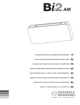
TABELLA
CARATTERISTICHE
ELETTRICHE(g.1)
G Tensione di alimentazione
H Sezione minima cavi
alimentazione
I Limiti min e max temperatura
di funzionamento
L Limiti min e max umidità
relativa di funzionamento
Per i dati degli assorbimenti
elettrici fare riferimento alla
targa delle caratteristiche
tecniche dell’unità.
1.2
1.3
SYMBOLS
The pictograms in the next
chapter provide the necessary
information for correct, safe
use of the machine in a rapid,
unmistakable way.
Index
- Paragraphs marked with this
symbol contain very important
information and recommenda-
tions, particularly as regards
safety.
Failure to comply with them may
result in:
- danger of injury to the opera-
tors
- loss of the warranty
- refusal of liability by the ma-
nufacturer.
Generic danger
- Signals to the personnel that
the operation described could
cause physical injury if not
performed according to the
safety rules.
Electrical hazard
- If the operation is not carried
out in compliance with the sa-
fety regulations there is a risk
of suffering physical injury due
to contact with components
under tension.
ELECTRICAL
CHARACTERISTICS TABLE
(g. 1)
G Power supply
H Power supply cable minimum
section
I Min and max operating
temperature limits
L Min and max operating
relative humidity
For information on electrical
consumption see the technical
features plate on the unit.
SYMBOLOGIE
Les pictogrammes reportés au
chapitre suivant permettent de
fournir rapidement et de ma-
nière univoque les informations
nécessaires pour une utilisation
correcte de la machine dans des
conditions de sécurité.
Index
- Les paragraphes précédés
par ce symbole contiennent
des informations et des pre-
scriptions très importantes,
notamment pour ce qui con-
cerne la sécurité.
Le non-respect peut comporter:
- danger pour la sécurité des
opérateurs.
- perte de la garantie du con-
trat.
- dégagement de la responsa-
bilité du fabricant.
Danger général
- Signale au personnel con-
cerné que l’opération décrite
présente, si elle n’est pas
effectuée conformément aux
normes de sécurité, le risque
de provoquer des dommages
physiques.
Danger électrique
- que l’opération décrite
présente, si elle n’est pas
effectuée dans le respect
des normes de sécurité, le
risque d’accidents dus au
contact avec des éléments
sous tension électrique.
TABLEAU DES
CARACTERISTIQUES
ELECTRIQUES(g.1)
G Tension d’alimentation
H Section minimum câbles
d’alimentation
I Limites mini et maxi
température de
fonctionnement
L Limites mini et maxi humidité
relative de fonctionnement
Pour les données des
absorptions électriques,
se reporter à la plaque des
caractéristiques de l’unité.
BILDSYMBOLE
Die im folgenden Kapitel
aufgeführten Bildsymbole liefern
schnell und eindeutig Informatio-
nen zum korrekten und sicheren
Gebrauch des Gerätes.
Inhaltsverzeichnis
- Die Paragrafen, denen dieses
Symbol vorausgeht, enthalten
sehr wichtige Informationen
und Vorschriften, insbeson-
dere bezüglich der Sicherheit.
Die Nichtbeachtung dieser Infor-
mationen und Vorschriften kann
dazu führen, dass:
- die Unversehrtheit des
Personals an den Geräten
gefährdet ist
- die vertragliche Garantie
verfällt
- die Herstellerfirma jede
Verantwortung ablehnt.
Allgemeine Gefahr
- Zeigt dem betreffenden Per-
sonal an, dass bei der be-
schriebenen Tätigkeit Ver-
letzungsgefahr besteht, wenn
diese nicht unter Beachtung
der Sicherheitsvorschriften
durchgeführt wird.
Gefahr durch elektrischen
Strom
- Der beschriebene Vorgang
bringt, falls nicht unter Einhal-
tung der Sicherheitsvorschrif-
ten durchgeführt, die Gefahr
von Verletzungen aufgrund
der Berührung unter elektri-
scher Spannung stehender
Elemente mit sich.
TABELLE DER
ELEKTRISCHEN
EIGENSCHAFTEN (Abb. 1)
G Versorgungsspannung
H Mindestquerschnitt
Versorgungskabel
I Min und Max Grenzen für
Betriebstemperatur
L Min und Max Grenzen für
relative Luftfeuchtigkeit bei
Betrieb
Entnehmen Sie die
Stromaufnahmewerte dem
Typenschild mit den technischen
Daten der Einheit.
1
V/ph/Hz
mm
2
°C
%
G
H
I
L
200 400 600 800 1000
230/1/50 + o - 10%
1,5
0-50
15-85

GB
F
D
10
I
12
2
2.1
2.2
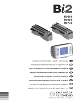
ISTRUZIONI
MONTAGGIO
APERTURA FIANCHI
- Smontare la griglia superiore
(g.2rif.A)svitandoledue
viti di fissaggio (fig. 2 rif.
B);
- sul lato sinistro svitare la
vite(g.2rif.C)chessail
anchetto sinistro (g. 2rif.
D),spostarlo leggermente
verso sinistra e sollevarlo;
- sul alto opposto sollevare il
coperchietto(g. 2 rif. E) di
coperturavite(g.2rif.F)e
svitarla;
- spostare leggermente verso
destrailanchettoesollevarlo
(g.2rif.G).
MONTAGGIO, SETTAGGIO
E CONNESSIONI PANNELLI
DI COMANDO A BORDO
MACCHINA B0642, B0643
I comandi dispongono di due
contatti puliti indipendenti per il
comando di un refrigeratore e
di una caldaia e di un ingresso
presenza; di una uscita a 230V
per il pilotaggio dell’elettrovalvola
estiva ed invernale.
INSTRUCTIONS
MOUNTING
SIDE OPENING
- Dismount the upper grill (g. 2
ref. A) by unscrewing the two
xing screws (g. 2 ref. B);
- on the left-hand side loosen
the screw (g. 2 ref. C) that
xes the left panel (g. 2 ref.
D), then move it slightly to the
left and lift it up;
- on the opposite side, lift
the cover (g. 2 ref. E) that
protects the screw (g. 2 ref.
F) and unscrew it;
- move the side panel slightly
to the right and lift it out (g. 2
ref. G).
MOUNTING, SETTING AND
CONNECTION OF ON-BOARD
MACHINE CONTROL PANELS
B0642, B0643
The controls have two
independent free contacts for
controlling a chiller and a boiler
and an energy saving inlet; a
230V outlet for controlling the
summer and winter solenoid
valve.
INSTRUCTIONS DE
MONTAGE
OUVERTURE FLANCS
- Démonter la grille supérieure
(g.2réf.A)endévissantles
deuxvisdexation(g.2réf.
B);
- sur le côté gauche, dévisser
lavis(g.2réf.C)quixele
ancgauche(g.2réf.D),le
déplacer légèrement vers la
gauche et le soulever;
- sur le côté opposé, soulever
le cache (fig. 2 réf. E) de
couverturevis (g. 2 réf. F)
et la dévisser;
- déplacerlégèrementleanc
vers la droite et le soulever
(g.2réf.G).
MONTAGE, PARAMETRAGE
ET CONNEXIONS DES
PUPITRES DE COMMANDE
SUR LA MACHINE B0642,
B0643
Les commandes disposent
de deux contacts propres
indépendants pour la commande
d’une chaudière et d’une entrée
présence ; d’une sortie 230V
pour le pilotage de l’électrovalve
estivale et hivernale.
MONTAGEANLEITUNG
ÖFFNUNG DER SEITEN
- Montieren Sie den oberen
Rost (Abb. 2 Pos. A) ab,
indem Sie die beiden
Befestigungsschrauben (Abb.
2 Pos. B) lösen;
- Lösen Sie auf der linken
Seite die Schraube (Abb. 2
Pos. C) zur Befestigung des
linken Flügels(Abb. 2 Pos. D),
versetzen diesen leicht nach
links und heben ihn an;
- Entfernen Sie auf der
gegenüberliegenden Seite
die Schutzkappe (Abb. 2 Pos.
E) der Schraube (Abb. 2 Pos.
F) nach oben und lösen die
Schraube;
- Verschieben Sie den Flügel
leicht nach rechts und
entfernen diesen nach oben
(Abb. 2 Pos. G).
MONTAGE, SETUP
UND ANSCHLÜSSE DER
BEDIENTAFEL AN BORD DER
MASCHINE B0642, B0643
Die Bedienelemente verfügen
über zwei unabhängige
potentialfreie Kontakte zur
Steuerung eines Kühlaggregats
und Heizkessels sowie eines
Anwesenheits-Engangs. Ein
230-V-Ausgang steuert das
Sommer- und Winterelektroventil
an.
2
A
B
B
C
D
E
G
F

GB
F
D
12
I
12
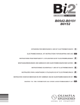
2.2.1 Montaggio
- Inlarelaprotezioneinferiore
(g.3rif.A)essarlaconle
dueviti(g.3rif.B);
- appoggiare il comando
(g. 3 rif. C) alla parete del
ventilconvettoreessarlocon
ledueviti(g.3rif.D);
- ssare il cavo di terra alla
struttura del ventilconvettore
utilizzando la vite a corredo (la
forza minima che deve essere
esercitata per l’avvitamento
deve essere di circa 4N);
- collegare i 2 connettori
rapidi del motore (MOTOR
e MOTOR SENS.) a quelli
presenti sulla scheda (g. 4
rif. A e B) *;
- collegare il connettore della
sonda acqua (g. 3 rif. F)
presente sul ventilconvettore;
la sonda temperatura acqua
controlla la temperatura
all’interno delle batterie
e determina l’avviamento
del ventilatore in base a
dei parametri reimpostati
(funzioni di minima invernale e
dimassimaestiva).Vericare
che sia correttamente inserita
nel pozzetto presente sulla
batteria.
- eseguire i collegamenti
elettrici, ordinare i cablaggi,
ssareicaviconl’ausiliodel
cavallottoindotazione(g.3
rif. G);
- rimontareilanchettoestetico
del ventilconvettore;
- avvitare la vite superiore sul
pannellodicontrollo(g.5rif.
A)
- posizionare il copri vite
(fig. 5 rif. B) nell’apposito
alloggiamento sul pannello di
controllo;
- rimontare la griglia di mandata
aria(g.5rif.C).
3
Mounting
- Insert the lower safety guard
(g. 3 ref. A) and fasten it using
the two screws (g. 3 ref. B);
- rest the control (g. 3 ref. C)
on the wall of the fan coil and
fasten it using the two screws
(g. 3 ref. D);
- x the earth wire to the cooler-
convector structure using the
supplied screws (the minimum
force of about 4N must be used
when screwing-up);
- connect the 2 rapid connectors
on the motor (MOTOR and
MOTOR SENS.) to those on
the board (g. 4 ref. A and B)
*;
- connect the water probe
connector (g. 3 ref. F) on the
cooler-radiator;
the water temperature probe
checks the temperature inside
the batteries and determines
the start of the fan based on
the set parameters (minimum
winter and maximum summer
functions). Check that it is
inserted correctly in the well
on the battery.
- make the electrical
connections, order the wiring
and x the wires using the
supplied clamp (g. 3 ref. G);
- mount the aesthetic side panel
on the Cooler-convector;
- tighten the upper screw on the
control panel (g. 5 ref. A);
- position the screw cover (g.
5 ref. B) in the special housing
on the control panel;
- remount the air inlet grill (g.
5 ref. C).
Montage
- Enlerlaprotectioninférieure
(g.3réf.A)etlaxeravec
lesdeuxvis(g.3réf.B);
- appuyerlacommande(g.3
réf. C) à la paroi du ventilateur-
convecteur et la fixer au
moyendesdeuxvis(g.3réf.
D);
- fixer le câble de terre du
ventilo-convecteur en utilisant
la vis fournie (la force minimum
qui doit être exercée pour le
vissage doit être d’environ
4N);
- brancher les 2 connecteurs
rapides du moteur (MOTOR
et MOTOR SENS.) aux
connecteurs présents sur la
carte(g.4réf.AetB)*;
- brancher le connecteur du
capteur eau (g. 3 réf. F)
présent sur le ventilateur-
convecteur ;
le capteur de température
eau contrôle la température
à l’intérieur des batteries et
commande le démarrage
du ventilateur sur la base
des paramètres congurés
(fonctions de minimum
hivernal et de maximum
estival). S’assurer qu’il est
correctement inséré dans
le logement présent sur la
batterie.
- effectuer les branchements
électriques, ordonner les
câblages, xer les câbles à
l’aidedexationfournies(g.
3 réf. G);
- remonter le anc esthétique
du ventilateur-convecteur;
- visser la vis supérieure sur le
panneaudecontrôle(g.5réf.
A);
- placerlecachevis(g.5réf.
B) dans le logement prévu à
cet effet sur le panneau de
contrôle;
- remonter la grille de
refoulementair(g.5réf.C).
Montage
- Führen Sie den unteren
Schutz (Abb. 3 Pos. A) ein und
befestigen ihn mit den beiden
Schrauben (Abb. 3 Pos. B).
- Setzen Sie die Steuerung
(Abb. 3 Pos. C) an die Wand
des Ventilkonvektors und
befestigen sie mit den beiden
Schrauben (Abb. 3 Pos. D);
- Befestigen Sie das Erdungskabel
an der Tragkonstruktion des
Ventil-Konvektors. Verwenden
Sie dazu die mitgelieferte
Schraube (die zum Anschrauben
mindestens aufzuwendende
Kraft beträgt zirka 4N).
- Verbinden Sie die 2
Schnellanschlüsse des Motors
(MOTOR und MOTOR SENS.)
mit den an der Karte bendlichen
Anschlüssen (Abb. 4 Pos. A und
B) *;
- Schließen Se den Verbinder der
Wassersonde (Abb. 3 Pos. F) am
Ventil-Konvektors an.
Die Wassertemperatursonde
kontrolliert die Temperatur
im Innern der Batterien und
bestimmt den Start des
Ventilators auf der Grundlage
der voreingestellten Parameter
(Funktionen Winter-Minimum
und Sommer-Maximum). Stellen
Sie sicher, dass die Sonde
korrekt im Schacht an der
Batterie eingesetzt ist.
- Führen Sie die elektrischen
Anschlüsse aus, ordnen Sie die
Verkabelungen und befestigen
Sie die Kabel unter Verwendung
mit mitgelieferte Zwinge (Abb. 3
Pos. G).
- Montieren Sie den Zierügel des
Ventil-Konvektors wieder.
- Ziehen Sie die obere Schraube
auf der Bedientafel (Abb. 5 Pos.
A) fest an.
- den Schraubendeckel (Abb. 5
Pos. B) in seiner Aufnahme auf
der Bedientafel positionieren;
- Bringen Sie das
Luftzuleitungsrost (Abb. 5
Pos. C) wieder an.
B
A
C
D

GB
F
D
14
I
12
6
200 - 1000 *
200 **
400 **
600 **
800 **
1000 **
A
B
C
D
E
F
2.2.2
(*) Se il motore è sprovvisto di
connettore MOTOR SENS
collegare la prolunga in
dotazione per la connessione
elettrica del cavo motore ed
effettuare la procedura di
programmazione descritta nel
paragrafo 2.2.2.
Programmazione
Questi pannelli elettronici se
collegati ai nuovi motori con
sensore magnetico di velocità
(sensore di Hall) effettuano
automaticamente la regolazione
del numero di giri del ventilatore
nelle varie funzioni.
In caso di guasto del sensore (vedi
paragrafo Segnalazione guasto
motore) o con motori privi di tale
dispositivo è possibile comunque
effettuare manualmente la
programmazione del modello.
- Alimentare elettricamente il
ventilconvettore dopo aver
eseguito gli allacciamenti
elettrici del pannello comandi.
- Con il pannello acceso in
qualsiasi funzione premere
il tasto MODE (g. 7 rif. A)
peralmeno20 secondi,no
aquandoil led(g.7 rif.B)
inizia a lampeggiare.
- A questo punto il numero di
lampeggi del led, con intervalli
di pausa di circa 3 secondi,
definisce il modello come
indicato in tabella
A lampeggio
continuo (motore
con sensore di Hall)
B 1 lampeggio
C 2 lampeggi
D 3 lampeggi
E 4 lampeggi
F 5 lampeggi
(*) If the motor is not fitted
with the MOTOR SENS
connector, connect the
supplied extension for the
electrical connection of the
motor cable and perform
the programming procedure
described in section 2.2.2.
Programming
When these electronic panels
are connected to the new motors
with magnetic speed sensor
(Hall sensor) they automatically
regulate the number of revs of
the fan in the various functions.
If there is a sensor failure (see
the motor fault signal section)
or the motors are without
this device the model can be
programmed manually.
- After making all the
connections of the control
panel power up the cooler-
convector
- With the panel ON in any
position press the MODE key
(g. 7 ref. A) for at least 20
seconds until the LED (g. 7
ref. B) starts to ash.
- At this point the number
of ashes of the LED, with
pause intervals of about 3
seconds, denes the model
as indicated in the table
A continual
flashing (motor
with Hall sensor)
B 1 ash
C 2 ashes
D 3 ashes
E 4 ashes
F 5 ashes
(*) Si le moteur est dépourvu de
connecteur MOTOR SENS,
brancher la rallonge fournie
pour la connexion électrique
du câble moteur et effectuer la
procédure de programmation
décrite au paragraphe 2.2.2.
Programmation
Ces panneaux électroniques,
s’ils sont branchés aux nouveaux
moteurs à capteur magnétique
de vitesse (capteur de Hall)
effectuent automatiquement le
réglage du nombre de tours du
ventilateur dans les différentes
fonctions.
En cas de panne du capteur
(voir paragraphe Indication
panne moteur) ou de moteurs
dépourvus de ce dispositif, il
est possible de toute façon
d’effectuer manuellement la
programmation du modèle.
- Alimenter électriquement le
ventilateur-convecteur après
avoir effectué les branchements
électriques du panneau de
commande.
- Le panneau étant allumé dans
n’importe quelle fonction,
appuyer sur la touche MODE
(fig. 7 réf. A) pendant au
moins 20 secondes jusqu’à
cequelevoyant(g.7réf.B)
commence de clignoter.
- A ce point, le nombre de
clignotements du voyant,
avec des intervalles de pause
d’environ3secondes,dénit
le modèle de la façon indiquée
dans le tableau
A clignotement continu
(moteurs avec capteur de
Hall)
B 1 clignotement
C 2 clignotements
D 3 clignotements
E 4 clignotements
F 5 clignotements
(*) Wenn der Motor nicht mit
dem Anschluss MOTOR
SENS ausgestattet ist,
verbinden Sie die mitgelieferte
Verlängerung für den
elektrischen Anschluss des
Motorkabels und führen die m
Abschnitt 2.2.2 beschriebene
Programmierprozedur durch.
Programmierung
Diese elektronischen
Schalttafeln führen beim
Anschluss an die neuen
Motoren mit Geschwindigkeits-
Magnetsensor automatisch die
Einstellung der Drehzahl des
Ventilators in den verschiedenen
Funktionen durch.
Im Fall einer Störung des Sensors
(siehe Abschnitt Meldung von
Motordefekt) oder bei Motoren
ohne diese Vorrichtung kann die
Programmierung des Modells in
jedem Fall manuell durchgeführt
werden.
- Speisen Sie den Ventil-
Konvektor elektrisch,
nachdem Sie die elektrischen
Anschlüsse der Bedientafel
hergestellt haben
- Drücken Sie bei der in
einer beliebigen Funktion
laufenden Bedientafel die
Taste MODE (Abb. 7 Pos. A)
für mindestens 20 Sekunden,
bis die Led (Abb. 7 Pos. B) zu
blinken beginnt.
- Die Anzahl Blinksignale
der Led in Intervallen von 3
Sekunden bestimmt hier das
Modell gemäß Angabe in der
Tabelle
A Dauerblinken (Motor
mit Hall-Sensor)
B 1 Blinkvorgang
C 2 Blinkvorgänge
D 3 Blinkvorgänge
E 4 Blinkvorgänge
F 5 Blinken
* con HALL - with HALL - avec HALL - mit HALL - con HALL - com HALL - met HALL - ìå HALL
** senza HALL - without HALL - sans HALL - ohne HALL - sin HALL - sem HALL - zonder HALL - ÷ùñßò HALL

GB
F
D
16
I
-Pervariareilmodelloèsufciente
premere nuovamente il tasto
MODE(g.7rif.A)contando
il numero di lampeggi, no
a quando corrisponderà al
modello di apparecchio da
programmare.
Ogni pressione del tasto
MODE corrisponde ad un
incremento di una grandezza.
- Una volta impostato
correttamente il modello
attendere 20 secondi senza
eseguire nessuna operazione.
- Il pannello di comando torna
nel modo di funzionamento
impostato prima della
procedura.
- Se si fosse in dubbio sul tipo di
programmazione effettuata, è
possibile ripetere l’operazione
più volte.
Montaggio sonda temperatura
aria (solo per modello B0642)
Per posizionare la sonda
temperatura(g.8rif.A):
- far passare la sonda nel foro
dellaspalla(g.8rif.B)
- infilare la sonda nel foro
inferiore(g.8rif.C)
- ssare la sonda all’apposito
aggancio(g.8rif.D).
8
12
2.2.3
- To change the model just
press the key MODE again
(fig. 7 ref. A), counting the
number of flashes until it
corresponds to the appliance
to be programmed.
Each time the MODE key is
pressed it corresponds to an
increase by one size.
- Once the model has been
set correctly wait for 20
seconds without performing
any operation.
- The control panel returns to
the operating mode set before
the procedure.
- If there is any doubt as to
which type of programming
has been set, the operation
can be repeated at will.
Mounting air temperature
probe (only for model B0642)
To position the temperature
probe (g. 8 ref. A):
- pass the probe through the
hole on the shoulder (g. 8
ref. B)
- insert the probe in the lower
hole (g. 8 ref. C)
- x the probe in the special
hook (g. 8 ref. D).
- Pour modifier le modèle, il
suft d’appuyerde nouveau
surla touche MODE (g. 7
réf. A) en comptant le nombre
de clignotements jusqu’à ce
qu’il corresponde au modèle
d’appareil à programmer.
Chaque pression de la touche
MODE correspond à une
augmentation d’une grandeur.
- Une fois le modèle
correctement paramétré,
attendre 20 secondes sans
effectuer aucune opération.
- Le panneau de commande
revient au mode de
fonctionnement paramétré
avant la procédure.
- En cas de doute concernant
le type de programmation
effectuée, il est possible de
répéter l’opération plusieurs
fois.
Montage du capteur de
température air (uniquement
pour modèle B0642)
Pour mettre en place le capteur
detempérature(g.8réf.A):
- faire passer le capteur dans
l’oricedumontant(g.8réf.
B)
- insérerlecapteurdansl’orice
inférieur(g.8réf.C)
- xerlasondeaucrochetprévu
àceteffet(g.8réf.D).
- Zur Änderung des Modells
reicht es aus, erneut die
Taste MODE (Abb. 7 Pos. A)
zu drücken und die Anzahl
Blinksignale zu zählen, bis
diese dem Modell des zu
programmierenden Gerätes
entspricht.
Jedem Drücken der Taste
MODE entspricht die
Zunahme einer Größe.
- Warten Sie nach korrekter
Einstellung des Modells 20
Sekunden, ohne irgendeinen
Vorgang auszuführen.
- Die Bedientafel kehrt in die
vor der Prozedur eingestellte
Betriebsart zurück.
- Bei Unklarheiten bezüglich
der durchgeführten
Programmierung kann der
Vorgang mehrmals wiederholt
werden.
Montage der
Lufttemperatursonde (nur für
Modell B0642)
Zur Position der Temperatursonde
(Abb. 8 Pos. A):
- Führen Sie die Sonde in die
Öffnung der Schulter (Abb. 8
Pos. B)
- Führen Sie die Sonde in die
untere Öffnung (Abb. 8 Pos.
C)
- Befestigen Sie die Sonde im
vorgesehenen Sitz (Abb. 8
Pos. D).
A
C
B
D

GB
F
D
18
I
Settaggio funzioni ausiliarie
dip-switch A e B
Sulla scheda elettronica del
comando sono posizionati due
dip-switchperlacongurazione
del funzionamento
dell’apparecchio in funzione
delle necessità.
- Tramite il cursore A (fig.
9) si modica la logica del
funzionamento notturno:
nella posizione ON viene
inibita la ventilazione
permettendo così alla
macchina di riscaldare gli
ambienti mediante convezione
naturale, come avviene
nei radiatori tradizionali; in
posizione OFF si ha invece
il normale funzionamento del
ventilatore.
- Posizionando il cursore B
(g.9)inONvieneabilitata,
solo in raffrescamento, la
ventilazione continua alla
minima velocità anche dopo
il raggiungimento del set
point (nella banda neutra)
per consentire un più regolare
funzionamento della sonda di
temperatura. Il passaggio alla
condizione di riscaldamento
annulla la condizione; con il
cursore nella posizione OFF
si disabilita tale funzione.
Impostazione ingresso
contatto presenza CP (g. 9
rif. C)
L’ingresso CP può essere
programmato con un valore
di offset del setpoint diverso
dai 2,5°C standard (da 0,5
a 8, 5°C) in fabbrica o da un
centro assistenza autorizzato su
preventiva richiesta del cliente.
Impostando il valore 0, alla
chiusura del contatto collegato
all’ingresso CP tutte le utenze
vengono spente.
Non è possibile collegare
l’ingresso in parallelo a quello
di altre schede elettroniche
(usare contatti separati).
9
12
2.2.4
2.2.5
BA
C
Setting auxiliary functions
dip-switches A and B
There are two dip-switches on
the electronic control panel
for setting the functions of the
appliance as required.
- Use cursor A (g. 9) to modify
the night function logic:
In the ON position the
ventilation is inhibited thus
letting the machine heat
the room through natural
convection as happens with
traditional radiators; in the
OFF position the fan functions
normally.
- Set cursor B (g. 9) to ON (in
cooling only) to enable the
continual ventilation at the
minimum speed, even after the
set point has been reached (in
the neutral band) to ensure a
more regular functioning of the
temperature probe. Passing
to heating will cancel this
condition; set the cursor set
to OFF to disable this function.
Setting CP presence contact
input (g. 9 rif. C)
Should the customer request it,
the CP input can be programmed
with an offset value of the
setpoint that is different from
the standard 2.5°C (from 0.5 to
8.5°C) in the factory or by an
authorised service centre. If the
value is set to 0, when the contact
connected to the CP input is
closed all the users connected
will be switched off.
The input cannot be connected
in parallel to one of another
electronic board (use separate
contacts).
Paramétrage des fonctions
auxiliaires dip-switch A et B
Sur la carte électronique de la
commande sont présents deux
dip-switches permettant la
congurationdufonctionnement
de l’appareil en fonction des
besoins.
- AumoyenducurseurA(g.
9),l’onmodielalogiquede
fonctionnement nocturne:
Dans la position ON, la
ventilation est inhibée, ce
qui permet à la machine de
réchauffer les pièces par
convexion naturelle, comme
cela a lieu avec les radiateurs
traditionnels ; en position
OFF, l’on a par contre le
fonctionnement normal du
ventilateur.
- EnplaçantlecurseurB(g.9)
sur ON, l’on active, uniquement
en refroidissement, la
ventilation continue à la
vitesse minimum, même une
fois que la valeur de consigne
a été atteinte (dans la bande
neutre), pour permettre un
fonctionnement plus régulier
du capteur de température.
Le passage à la condition de
chauffage annule la condition
; avec le curseur en position
OFF, l’on désactive cette
fonction.
Paramétrage entrée contact
présence CP (g.9réf.C)
L’entrée CP peut être
programmée avec une valeur
d’écart de consigne différente
des 2,5°C standard (de 0,5 à
8,5°C) en usine ou par un centre
d’assistance agréé sur demande
du client. En paramétrant la
valeur 0, lors de la fermeture
du contact branché à l’entrée
CP, toutes les utilisations sont
éteintes.
Il n’est pas possible de relier
l’entrée en parallèle à l’entrée
d’autres cartes électroniques
(utiliser des contacts séparés).
Setup der Hilfsfunktionen Dip-
Switch A und B
An der Elektronikkarte der
Steuerung benden sich zwei
Dip-Switches zur Konguration
des Gerätebetriebs je nach
Erfordernis.
- Mit Hilfe des Schiebers A (Abb.
9) wird die Nachtbetriebslogik
verändert:
In der Position ON wird die
Belüftung gehemmt, sodass
die Maschine die natürliche
Konvektion heizen kann, wie
es auch bei herkömmlichen
Radiatoren der Fall ist. In der
Position OFF erhalten Sie
hingegen den Normalbetrieb
des Ventilators.
- Beim Positionieren des
Schiebers B (Abb. 9) auf
ON wird, nur im Kühlmodus,
die Dauerbelüftung bei der
Mindestgeschwindigkeit
auch nach dem Erreichen
des Setpoints (im neutralen
Bereich) freigegeben, um
einen reguläreren Betrieb
der Temperatursonde zu
ermöglichen. Der Übergang
auf den Heizmodus hebt
diesen Zustand auf. Mit dem
Schieber in der Position
OFF wird diese Funktion
deaktiviert.
Einstellung Eingang Kontakt
Vorhandensein CP (Abb. 9
Pos. C)
Der Eingang kann auf Anfrage
des Kunden ab Werk oder
durch ein autorisiertes
Kundendienstzentrum auf
einem vom Standard 2,5°C
abweichenden Setpoint-
Offset-Wert (zwischen 0,5
und 8,5°C) eingestellt werden.
Beim Einstellen des Wertes 0
werden beim Schließen des mit
dem Eingang CP verbundenen
Kontakts alle Verbraucher
abgeschaltet.
Es ist nicht möglich, den
Eingang parallel zu den
anderen Elektronikkarten zu
schalten (getrennte Kontakte
verwenden).

GB
F
D
20
I
10
Connessioni B0642
H2 sonda temperatura acqua
calda
H4 sonda temperatura acqua
fredda
AIR sonda temperatura aria
C1 condensatore
M1 motore ventilatore
S1 microinterruttore sicurezza
griglia
Y1 elettrovalvola acqua calda
(uscita in tensione a 230V/
50Hz 1A)
L-N collegamento alimentazione
elettrica 230V/50Hz
E uscita consenso caldaia
(contatto pulito max 1A)
F uscita consenso
refrigeratore (contatto pulito
max 1A)
FF servomotori pannello
aspirazione mobile (uscita
in tensione a 230V/ 50Hz
1A)
CP ingresso sensore presenza
(se chiuso, il set point viene
ridotto o incrementato in
funzione del modo attivo
di 2.5 °C)
X componenti montati a bordo
macchina Bi2
B0642
12
2.2.6
CP
F
E
X
B0642 connections
H2 hot water temperature
probe
H4 cold water temperature
probe
AIR air temperature probe
C1 condenser
M1 fan motor
S1 grill safety micro-switch
Y1 hot water solenoid valve
(230V/50Hz 1A powered
output)
L-N 230V/50Hz electrical power
supply connection
E boiler go-ahead output (free
contact max 1A)
F chiller go-ahead output (free
contact max 1A)
FF servomotor mobile
aspiration panel
(230V/50Hz 1A powered
output)
CP presence sensor input
(if closed, the set point
is reduced or increased
depending on the active
mode by 2.5 ° C)
X components mounted on-
board the Bi2 machine
Connexions B0642
H2 capteur de température eau
chaude
H4 capteur de température eau
froide
AIR capteur de température air
C1 condensateur
M1 moteur ventilateur
S1 micro-interrupteur de
sécurité grille
Y1 électrovalve eau chaude
(sortie sous tension à 230V/
50Hz 1A)
L-N branchement alimentation
électrique 230V/50Hz
E sortie consentement
chaudière (contact propre
maxi 1A)
F sortie consentement
réfrigérateur (contact
propre maxi 1A)
FF servomoteurs du panneau
d’aspiration mobile (sortie
sous tension à 230V/ 50Hz
1A)
CP entrée capteur présence
(si fermée, la valeur de
consigne est réduite ou
augmentée en fonction du
mode actif de 2.5 °C)
X composants montés sur
machine Bi2
Anschlüsse B0642
H2 Heißwasser-
Temperatursonde
H4 Kaltwasser-
Temperatursonde
AIR Luft-Temperatursonde
C1 Kondensator
M1 Ventilator-Motor
S1 Mikroschalter Sicherung
Rost
Y1 Heißwasser-Elektroventil
(Spannungsausgang bei
230V/ 50 Hz 1A)
L-N Elektrischer
Stromanschluss 230 V /
50 Hz
E Ausgang Freigabe
Heizkessel (potentialfreier
Kontakt max 1A)
F Ausgang Freigabe Kühler
(potentialfreier Kontakt max
1A)
FF Servomotoren
bewegliche Saugtafel
(Spannungsausgang bei
230V/ 50 Hz 1A)
CP Eingang Sensor
Vorhandensein (falls
geschlossen, wird der
Setpoint in Abhängigkeit
des aktiven Modus um
2.5 °C herabgesetzt oder
erhöht)
X An Bord der Maschine Bi2
montierte Komponenten

GB
F
D
22
I
Connessioni B0643
A-B collegamento seriale
per comando remoto a
muro B0373 (rispettare la
polarizzazione A-B)
H2 sonda temperatura acqua
calda
H4 sonda temperatura acqua
fredda
G Resistenza da 120 ohm
per la terminazione della
connessione seriale
C1 condensatore
M1 motore ventilatore
S1 microinterruttore sicurezza
griglia
Y1 elettrovalvola acqua (uscita
in tensione a 230V/ 50Hz
1A)
L-N collegamento alimentazione
elettrica 230V/50Hz
E uscita consenso caldaia
(contatto pulito max 1A)
F uscita consenso
refrigeratore (contatto pulito
max 1A)
FF servomotori pannello
aspirazione mobile (uscita
in tensione a 230V/ 50Hz
1A)
CP ingresso sensore presenza
(se chiuso, il set point viene
ridotto o incrementato in
funzione del modo attivo
di 2.5 °C)
X componenti montati a bordo
macchina Bi2.
11
B0643
12
2.2.7
CP
F
E
X
A-B
G
B0643 connections
A-B Serial connection for wall-
mounted remote control
B0373 (respect the A-B
polarisation)
H2 hot water temperature
probe
H4 cold water temperature
probe
G 120 ohm resistance for the
termination of the serial
connection
C1 condenser
M1 fan motor
S1 grill safety micro-switch
Y1 water solenoid valve
(230V/50Hz 1A powered
output)
L-N 230V/50Hz electrical power
supply connection
E boiler go-ahead output (free
contact max 1A)
F chiller go-ahead output (free
contact max 1A)
FF servomotor mobile
aspiration panel
(230V/50Hz 1A powered
output)
CP presence sensor input
(if closed, the set point
is reduced or increased
depending on the active
mode by 2.5 ° C)
X components mounted on-
board the Bi2 machine.
Connexions B0643
A-B branchement série pour
commande à distance
murale B0373 (respecter
la polarisation A-B)
H2 capteur de température eau
chaude
H4 capteur de température eau
froide
G Résistance 120 ohms pour
la cessation de la connexion
série
C1 condensateur
M1 moteur ventilateur
S1 micro-interrupteur de
sécurité grille
Y1 électrovalve eau (sortie
sous tension à 230V/ 50Hz
1A)
L-N branchement alimentation
électrique 230V/50Hz
E sortie consentement
chaudière (contact propre
maxi 1A)
F sortie consentement
réfrigérateur (contact
propre maxi 1A)
FF servomoteurs du panneau
d’aspiration mobile (sortie
sous tension à 230V/ 50Hz
1A)
CP entrée capteur présence
(si fermée, la valeur de
consigne est réduite ou
augmentée en fonction du
mode actif de 2.5 °C)
X composants montés sur
machine Bi2.
Anschlüsse B0643
A-B Reihenanschluss für
Fernsteuerung an der
Wand B0373 (Polung
beachten A-B)
H2 Heißwasser-
Temperatursonde
H4 Kaltwasser-
Temperatursonde
G 120 Ohm Widerstand für
den Abschluss der seriellen
Verbindung
C1 Kondensator
M1 Ventilator-Motor
S1 Mikroschalter Sicherung
Rost
Y1 Wasser-Elektroventil
(Spannungsausgang bei
230V/ 50 Hz 1A)
L-N elektrischer
Stromanschluss 230 V /
50 Hz
E Ausgang Freigabe
Heizkessel (potentialfreier
Kontakt max 1A)
F Ausgang Freigabe Kühler
(potentialfreier Kontakt
max 1A)
FF Servomotoren
bewegliche Saugtafel
(Spannungsausgang bei
230V/ 50 Hz 1A)
CP Eingang Sensor
Vorhandensein (falls
geschlossen, wird der
Setpoint in Abhängigkeit
des aktiven Modus um
2.5 °C herabgesetzt oder
erhöht).
X An Bord der Maschine Bi2
montierte Komponenten.

GB
F
D
24
I
MONTAGGIO B0373
Il controllo remoto a muro
B0373 è un termostato
elettronico (dotato di sonda di
temperatura) con possibilità
di controllo su uno o più
ventilconvettori/ventilradiatori
(fino ad un massimo di 30)
dotati di comando elettronico
per remotizzazione B0372 o
B0375. Viene fornito a corredo
un trasformatore da 230/12 V
per l’alimentazione elettrica del
controllo.
- Installare il controllo remoto a
muro B0373 lontano da porte
e/onestreedafontidicalore
(caloriferi, ventilconvettori,
fornelli, raggi diretti del
sole), su pareti interne e ad
un’altezza di circa 1,5 m dal
pavimento.
Il controllo remoto a muro è
presente all’interno della
confezione già assemblato,
pertanto seguire le seguenti
istruzioniperilssaggio:
- aprire il coperchio facendo
leva sui due dentini inferiori
conuncacciavite(g.12);
- svitareleduevitidissaggio
della scheda elettronica alla
basedelcontrollo(g.13rif.
X);
- utilizzare la base del controllo
per tracciare a muro i punti di
ssaggio(utilizzareiduefori
opposti);
- forare la parete;
- passare i cavi elettrici
attraversolenestrepresenti
sulla base;
- ssarela base del controllo
alla parete utilizzando tasselli
adeguati.
12
12
2.3 MOUNTING B0373
The wall-mounted B0373 is an
electronic thermostat (tted with
temperature probe) with the
possibility of controlling one or
more cooler-convector/cooler-
radiators (up to a maximum of
30) equipped with electronic
control for allowing remote
control B0372 or B0375. A
230/12 V transformer is supplied
for the electric power supply of
the control.
- Install the wall-mounted
remote control B0373 away
from doors or windows and
sources of heat (heaters,
convectors, stoves, direct
sunlight), on internal walls at
a height of about 1.5 m from
the oor.
The wall-mounted remote
control is already assembled
in the package so follow the
following mounting instructions:
- open the cover by levering
the two lower lugs with a
screwdriver (g. 12);
- unscrew the two xing screws
on the electronic boards at the
base of the control (g. 13 ref.
X);
- use the base of the control to
trace the xing point on the
wall (use the two opposite
holes);
- drill the holes in the wall;
- route the electric wires
through the windows on the
base;
- x the base of the control to
the wall using suitable plugs.
MONTAGE B0373
Le contrôle à distance mural
B0373 est un thermostat
électronique (doté d’une sonde
de température), avec possibilité
de contrôler un ou plusieurs
ventilateurs-convecteurs/
ventilateurs-radiateurs (jusqu’à
un maximum de 30) dotés
de commande électronique
à distance B0372 ou B0375.
Un transformateur 230/12 V
est fourni pour l’alimentation
électrique du contrôle.
- Installer la commande à
distance au mur B0373 loin
des portes et/ou fenêtres
et des sources de chaleur
(radiateurs, ventilateurs-
convecteurs, rayons solaires,
cuisinières), sur les murs
intérieurs et à une hauteur
d’environ 1,5 m du sol.
Le contrôle à distance mural
est présent à l’intérieur de
l’emballage déjà assemblé,
par conséquent suivre les
instructions suivantes pour la
xation:
- ouvrir le couvercle en prenant
appui sur les deux dents
inférieures avec un tournevis
(g.12);
- dévisser les deux vis
de fixation de la carte
électronique à la base du
contrôle(g.13réf.X);
- utiliser la base du contrôle
pour tracer au mur les points
dexation (utiliser les deux
oricesopposés)
- percer le mur
- passer les câbles électriques
à travers les fenêtres
présentes sur la base
- xerla base du contrôle au
mur en utilisant les chevilles
appropriées.
MONTAGE B0373
Die Wand-Fernsteuerung
B0373 ist ein elektronisches
Thermostat (ausgestattet
mit Temperatursonde) mit
der Möglichkeit, einen oder
mehrere (bis maximale
30) mit Fernbedienungs-
Elektroniksteuerung B0372 oder
B0375 ausgestattete Ventil-
Radiatoren/Ventil-Konvektoren
zu kontrollieren.
Zum Lieferumfang gehört ein
Transformator 230/12 V für die
elektrische Stromversorgung
der Steuerung.
- Installieren Sie die Wand-
Fernsteuerung B0373 fern von
Türen und/oder Fenstern und
Wärmequellen (Heizkörpern,
Ventil-Konvektoren, Öfen,
direkte Sonnenstrahlen) an
Innenwänden auf einer Höhe
von zirka 1,5 m über dem
Fußboden.
Die Wand-Fernsteuerung
befindet sich bereits
zusammengebaut im Innern
der Packung. Gehen Sie daher
wie folgt zur Befestigung vor:
- Öffnen Sie den Deckel, indem
Sie die beiden unteren Zähne
mit einem Schraubenzieher
anhebeln (Abb. 12);
- Lösen Sie die beiden
Schrauben zur Befestigung
der Elektronikkarte am Sockel
der Steuerung (Abb. 13 Pos.
X).
- Verwenden Sie den Sockel
der Steuerung, um die
Befestigungspunkte an
der Wand vorzuzeichnen
(verwenden Sie zwei
gegenüberliegende
Bohrungen).
- Bohren Sie die Wand.
- Führen Sie die Stromkabel
durch die Fenster am Sockel.
- Befestigen Sie den Sockel der
Steuerung unter Verwendung
passender Dübel an der
Wand.

GB
F
D
26
I
14
COLLEGAMENTI
Collegare il controllo remoto
amuro ad uno o più (no ad
un massimo di 30) ventil-
radiatori/ventilconvettori dotati
di comando elettronico per
remotizzazione B0372 o B0375
mediante cavo bipolare adatto
per connessione seriale RS485
tenendolo separato dai cavi
d’alimentazione elettrica.
- Eseguire un tracciato in
modo da ridurre al minimo la
lunghezza delle derivazioni;
- terminare la linea con la
resistenza da 120 ohm in
dotazione;
- non effettuare collegamenti a
“stella”;
- il collegamento con il cavo
RS485 è polarizzato,
rispettare le indicazioni
“A” e “B” su ogni periferica
collegata (g.14 - 15) (per
la connessione utilizzare
preferibilmente un cavo
bipolare schermato con
sezione minima di 0,35 mm
2
);
- alimentare il controllo remoto
con un trasformatore il cui
secondario fornisca 12 V ed
almeno 1,5 VA.
12
2.4 CONNECTIONS
Connect the wall-mounted
remote control to one or more
cooler-convector/cooler-
radiators (up to a maximum of
30) equipped with electronic
control for allowing remote
control B0372 or B0375 using
bi-polar cable suitable for RS485
serial connections keeping it
separate from the electrical
cables.
- Route the connections in such
a way as to keep the length of
the junctions to a minimum;
- terminate the line with the 120
ohm resistance supplied;
- do not make any ‘star’
connections;
- the connection with the RS485
cable is polarised, respect the
“A” and “B” indications on
each connected peripheral
(fig. 14 - 15) (for the
connection use a screened
bipolar cable with a minimum
section of 0.35 mm
2
);
- power the remote control
with a transformer whose
secondary supplies 12V and
at least 1.5VA.
BRANCHEMENTS
Brancher le contrôle à distance
mural à un ou plusieurs
(jusqu’à un maximum de
30) ventilateurs-radiateurs/
ventilateurs-convecteurs dotés
d’une commande électronique
pour le contrôle à distance
B0372 ou B0375 au moyen d’un
câble bipolaire approprié pour
branchement série RS485, en
le gardant séparé des câbles
d’alimentation électrique.
- Effectuer un tracé de façon
à réduire au minimum la
longueur des dérivations;
- terminer la ligne avec la
résistance 120 ohm fournie;
- ne pas effectuer des
branchements en étoile;
- le branchement avec le câble
RS485 est polarisé, respecter
les indications “A” et “B” sur
chaquepériphériquerelié(g.
14 -15) (pour la connexion
utiliser de préférence un câble
bipolaire blindé d’une section
minimale de 0,35 mm
2
);
- alimenter le contrôle à distance
avec un transformateur dont
le secondaire doit fournir 12
V et au moins 1,5 VA.
ANSCHLÜSSE
Verbinden Sie die Wand-
Fernsteuerung mit einem oder
mehreren (bis maximal 30) Ventil-
Radiatoren/Ventil-Konvektoren,
die mit elektronischere
Fernbedienungssteuerung
B0372 oder B0375 ausgestattet
sind. Verwenden Sie dazu
für den seriellen Anschluss
RS485 geeignetes zweipoliges
Kabel, das getrennt von den
Stromkabeln zu halten ist.
- Führen Sie das Kabel so, dass
die Länge der Abzweigungen
auf ein Minimum reduziert
wird.
- Schließen Sie die Leitung mit
dem mitgelieferten 120-Ohm-
Widerstand ab.
- Führen Sie in keinem Fall
“Stern”-Anschlüsse aus.
- Der Anschluss mit dem RS485
Kabel ist gepolt. Halten Sie
die Angaben “A” und “B” auf
jeder Peripherie (Abb. 14 -
15) ein (Verwenden Sie für
den Anschluss vorzugsweise
eine abgeschirmtes
zweipoliges Kabel mit einem
Mindestquerschnitt von 0,35
mm
2
).
- Speisen Sie die Fernsteuerung
mit einem Transformator,
dessen Sekundärwicklung
12 V und mindestens 1,5 VA
liefert.

GB
F
D
28
I
Connessione ingresso
contatto presenza CP
L’ingresso CP va connesso
ad un contatto pulito (non in
tensione) e permette di ridurre
o incrementare in funzione del
modo attivo di 2.5 °C il setpoint
impostato dal termostato a tutti
i ventilradiatori/ventilconvettori
connessi. Su preventiva
richiesta del cliente, può essere
programmato con valore di offset
diverso dai 2,5°C standard (da
0,5 a 8,5°C) impostato sui singoli
ventilradiatori/ventilconvettori
connessi, in fabbrica o da un
centro assistenza autorizzato.
Impostando il valore 0, alla
chiusura del contatto collegato
all’ingresso CP tutte le utenze
vengono spente.
Il pannello B0643 connesso
al B0373 non necessita della
procedurad'autocongurazione
degli indirizzi
12
2.4.1 CP presence contact input
connection
The CP input must be connected
to a free contact (not powered)
and, depending on the mode
which is active, can reduce or
increase the setpoint by 2.5°
C from the thermostat to all
the cooler-convectors/cooler-
radiators connected. Should
the customer request it, the CP
input can be programmed in
the factory or by an authorised
service centre with an offset
value of the setpoint that is
different from the standard 2.5°C
(from 0.5 to 8.5°C) set on the
individual cooler-convectors/
cooler-radiators connected. If
the value is set to 0, when the
contact connected to the CP
input is closed all the users
connected will be switched off.
The panel B0643 connected
to B0373 does not require the
addresses to be auto-congured.
Connexion entrée contact
présence CP
L’entrée CP doit être connectée
à un contact propre (pas
sous tension) et elle permet
de réduire ou d’augmenter
en fonction du mode actif de
2.5 °C la valeur de consigne
paramétrée par le thermostat
pour tous les ventilateurs-
radiateurs/ventilateurs-
convecteurs connectés. Sur
demande préalable du client, il
peut être programmé avec une
valeur d’offset différente des
2,5°C standard (de 0,5 à 8,5°C),
configurée sur les différents
ventilateurs-radiateurs/
ventilateurs-convecteurs
connectés, en usine ou par
un centre d’assistance agréé.
En paramétrant la valeur 0,
lors de la fermeture du contact
branché à l’entrée CP, toutes les
utilisations sont éteintes.
Le pupitre B0643 connecté
au B0373 ne nécessite pas la
procédure d’autoconguration
des adresses.
Anschluss Eingang Kontakt
Vorhandensein CP
Der Eingang CP ist an einen
potentialfreien Kontakt (nicht
unter Spannung) zu legen und
erlaubt allen angeschlossenen
Ventilradiatoren/
Ventilkonvektoren je nach
aktivem Modus die Reduzierung
oder Erhöhung des vom
Thermostat aus eingestellten
Setpoints um 2,5 °C. Der Eingang
kann auf Anfrage des Kunden ab
Werk oder durch ein autorisiertes
Kundendienstzentrum
auf einem vom an den
einzelnen Ventilradiatoren/
Ventilkonvektoren eingestellten
Standard 2,5°C abweichenden
Setpoint-Offset-Wert (zwischen
0,5 und 8,5°C) programmiert
werden Beim Einstellen
des Wertes 0 werden beim
Schließen des mit dem Eingang
CP verbundenen Kontakts alle
Verbraucher abgeschaltet.
Die mit B0373 verbundene
Tafel B0643 erfordert nicht
die Prozedur der selbsttätigen
Adressenkonguration.

GB
F
D
30
I
16
USO
COMANDO ELETTRONICO
CON BARRA LED A BORDO
MACCHINA (B0642) (g.16)
Il comando rende completamente
autonoma la regolazione
della temperatura ambiente
tramite i programmi AUTO,
SILENZIOSO, NOTTURNO e
MAX per mezzo di una sonda
posizionata nella parte inferiore
del ventilconvettore e garantisce
una sicurezza antigelo anche
quando è posto in stand-by.
Il comando è installabile sulla
versione SLN.
A Led blu raffrescamento
B Tasto diminuzione
temperatura impostata
C Led blu fuoriscala di 5°C
D Barra Led setpoint regolabile
da 16 a 28 °C
E Led rosso fuoriscala di 40°C
F Tasto aumento temperatura
impostata
G Led rosso riscaldamento
H Tasto funzionamento estivo/
invernale
I Led giallo supervisione
da webserver attiva
L Indicatore di
funzionamento automatico
M Indicatore di
funzionamento silenzioso
N Indicatore di
funzionamento notturno
O Indicatore di velocità
ventilazione massima
P Led giallo di blocco per
acqua non in temperatura
Q Tasto MODE: ON/OFF -
selezione modalità di
funzionamento e Reset
segnalazioneltrosporco.
13
3
3.1
A
H
B
I
C
L
D
M N
E
O
F
P
G
Q
USE
ELECTRONIC CONTROL
WITH LED BAR ON-BOARD
THE MACHINE (B0642) (g. 16)
The command makes the
temperature regulation
completely autonomous through
the AUTO, SILENT, NIGHT
and MAX programmes, with a
probe positioned in the lower
part of the cooler-radiator, and
guarantees anti-freeze security
even when in stand-by. The
command can be installed on
the SLN version.
A Blue LED cooling
B Decrease set temperature
button
C Blue LED 5°C extreme
exceeded
D LED bar setpoint settable
from 16 to 28 °C
E Red LED 40°C extreme
exceeded
F Increase set temperature
button
G Red LED heating
H Summer/winter function
button
I Yellow LED Webserver
supervision active
L Automatic function
indicator
M Silent function indicator
N Night function indicator
O Maximum ventilation
speed indicator
P Yellow LED block due
to water not in temperature
Q MODE button: ON/OFF -
select operating mode and
reset dirty lter signal
UTILISATION
COMMANDE ELECTRONIQUE
AVEC BARRE A DIODES SUR
MACHINE (B0642) (g.16)
La commande rend entièrement
autonome le réglage de la
température ambiante au
moyen des programmes AUTO,
SILENCIEUX, NOCTURNE
et MAX à l’aide d’un capteur
situé dans la partie inférieure
di ventilateur-convecteur, et
elle assure une sécurité antigel
même quand elle est mise
en veille. La commande est
installable sur la version SLN.
A Diode bleue refroidissement
B Touche de diminution de la
température paramétrée
C Diode bleue valeur extrême
de 5°C
D Barre à diodes valeur de
consigne réglable de 16 à
28 °C
E Diode rouge valeur extrême
de 40°C
F Touche augmentation
température paramétrée
G Diode rouge chauffage
H Touche fonctionnement
estival/hivernal
I Diode jaune
supervision par serveur
Web active
L Indicateur de
fonctionnement
automatique
M Indicateur de
fonctionnement silencieux
N Indicateur de
fonctionnement nocturne
O Indicateur de vitesse
ventilation maximum
P Diode jaune de
blocage pour température
eau non atteinte
Q Touche MODE: ON/
OFF - sélection mode de
fonctionnement et Reset
indicationltreencrassé.
BEDIENUNG
ELEKTRONISCHE
STEUERUNG MIT LED-LEISTE
AN BORD DER MASCHINE
(B0642) (Abb. 16)
Die Steuerung sieht die vollkommen
unabhängige Regelung der
Umgebungstemperatur der
Programme MAX, AUTO,
GERÄUSCHARM und
NACHTBETRIEB mittels einer im
unteren Tel des Ventilkonvektors
positionierten Sonde vor und
garantiert einen Frostschutz auch
im Stand-by-Modus. Die Steuerung
kann auf den Ausführungen SLN
installiert werden.
A Blaue Led Kühlung
B Taste zur Herabsetzung der
eingestellten Temperatur
C Blaue Led 5°C
Skalenüberschreitung
D Setpoint-Led-Leiste, einstellbar
zwischen 16 und 28 °C
E Rote Led 40°C
Skalenüberschreitung
F Taste zur Erhöhung der
eingestellten Temperatur
G Rote Led Heizung
H Taste für Sommer-/
Winterbetrieb
I Gelbe Led Überwachung
von Webserver aktiv
L Anzeige des
Automatikbetriebes
M Anzeige des
geräuscharmen Betriebs
N Anzeige des
Nachtbetriebs
O Anzeige der maximalen
Belüftungsgeschwindigkeit
P Gelbe Led Sperre wegen
Wasser nicht auf Temperatur
Q MODE-Taste ON/OFF - Wahl
der Betriebsart und Reset der
Meldung Filter verschmutzt.

GB
F
D
32
I
13
3.1.1
3.1.2
3.1.3
3.1.4
Accensione generale
Per la gestione del
ventilconvettore attraverso il
pannello di controllo questa
deve essere collegata alla rete
elettrica.
Nel caso sia stato previsto
un interruttore generale sulla
linea elettrica di alimentazione,
questo deve essere inserito.
Tasto MODE(g.16rif.Q)
Consente di impostare il modo
di funzionamento del v e n t i l c
o n v e t t o r e .
Ad ogni pressione del
tasto vengono impostati
sequenzialmente i seguenti
modi:
- funzionamento automatico
- funzionamento silenzioso
- funzionamento notturno
- massima velocità di
ventilazione
Attivazione
Per attivare il ventilconvettore :
- Accendere l’impianto
inserendo l’interruttore
generale
- PremereiltastoMODE(g.16
rif. Q) e selezionare uno dei
modi di funzionamento.
Selezione manuale
riscaldamento/
raffrescamento.
Ad ogni pressione del tasto est/
inv (g.19 rif. H) corrisponde
una commutazione del modo
di regolazione estate/inverno
effettuato dal comando visibile
attraverso l’ accensione dei 2
LED rosso riscaldamento (g.
19 rif. G) o blu raffrescamento
(g.19rif.A).
InriscaldamentoilLEDrosso(g.
19 rif. G) è acceso con setpoint
superiore alla temperatura
ambiente, spenti entrambi rosso
e blu con setpoint inferiore.
InraffrescamentoilLEDblu(g.
19 rif. A) è acceso con setpoint
inferiore alla temperatura
ambiente, spenti entrambi blu
e rosso con setpoint superiore.
General switching on
To manage the cooler-convector
from the control panel, this
control must be connected to
the mains power supply.
If there is a master switch on the
mains power supply then it must
be switched on.
MODE button (g. 16 ref. Q)
For setting the operating mode
on the cooler-convector.
Each time the button is pressed
the following operating modes
are set in sequence:
- automatic function
- silent function
- night function
- maximum ventilation speed
Activation
To activate the cooler-convector:
- Switch on the system by
inserting the master switch
- Press the MODE button
(g.16 ref. Q) and select one
of the operating modes.
Manual heating/cooling
selection.
Each time the sum/win button
(fig. 19 ref. H) is pressed it
corresponds to the change of the
summer/winter regulation mode
performed by the command and
visible through the lighting up of
the 2 Red heating LED (g. 19
ref. G) or the blue cooling LED
(g. 19 ref. A).
In heating the Red LED (fig.
19 ref. G) is alight when the
setpoint is higher than the room
temperature, when the setpoint
is lower both red and blue are
OFF.
In cooling, the Blue LED
(fig. 19 ref. A) is alight if the
setpoint is lower than the room
temperature, if it is higher, both
red and blue LEDs are OFF.
Allumage général
Pour la gestion du ventilateur-
convecteur au moyen du
panneau de commande,
l’appareil doit être branché au
secteur.
Si l’on a prévu un interrupteur
général sur la ligne électrique
d’alimentation, celui-ci doit être
enclenché.
Touche MODE(g.16réf.Q)
Elle permet de paramétrer
le mode de fonctionnement
du ventilateur-convecteur. A
chaque pression de la touche,
les modes suivants sont
paramétrés en séquence:
- fonctionnement automatique
- fonctionnement silencieux
- fonctionnement nocturne
- vitesse maximum de
ventilation
Activation
Pour activer le ventilateur-
convecteur:
- Allumer l’appareil en
actionnant l’interrupteur
général
- Appuyer sur la touche
MODE (fig. 16 réf. Q) et
sélectionner l’un des modes
de fonctionnement.
Sélection manuelle chauffage/
refroidissement.
A chaque pression de la touche
été/hiv(g.19réf.H)correspond
une commutation du mode de
réglage été/hiver effectué par
la commande visible à travers
l’allumage des 2 diodes, rouge
chauffage (fig. 19 réf. G), ou
bleuerefroidissement (g. 19
réf. A).
En chauffage, la diode rouge
(fig. 19 réf. G) est allumée
avec une valeur de consigne
supérieure à la température
ambiante, les diodes rouge et
bleue sont toutes deux éteintes
avec une valeur de consigne
inférieure.
En refroidissement, la diode
bleue(g.19réf.A)estallumée
avec une valeur de consigne
inférieure à la température
ambiante, les diodes bleue et
rouge sont toutes deux éteintes
avec une valeur de consigne
supérieure.
Haupteinschaltung
Zur Verwaltung der Einheit
Ventilkonvektor über die
Bedientafel muss die Einheit
an das elektrische Stromnetz
angeschlossen sein.
Sollte ein Hauptschalter auf
der elektrischen Stromleitung
vorhanden sein, muss dieser
eingeschaltet sein.
MODE-Taste (Abb. 16 Pos. Q)
Erlaubt die Einstellung
der Betriebsart für den
Ventilkonvektor Bei jedem
Drücken der Taste werden
nacheinander folgende
Betriebsarten eingestellt:
- Automatikbetrieb
- Geräuscharmer Betrieb
- Nachtbetrieb
- Maximale
Belüftungsgeschwindigkeit
Aktivierung
Zur Aktivierung des
Ventilkonvektors:
- Schalten Sie die Anlage durch
Betätigen des Hauptschalters
ein.
- Drücken Sie die Taste MODE
(Abb. 16 Pos. Q) und wählen
Sie eine der Betriebsarten.
Manuelle Wahl Heizung /
Kühlung
Jedem Drücken der Taste
Sommer/Winter (Abb. 19 Pos.
H) entspricht eine Umschaltung
des Regelmodus Sommer/
Winter, durchgeführt von der
durch das Aufleuchten der 2
LED, rot für Heizung (Abb. 19
Pos. G) oder blau für Kühlung
(Abb. 19 Pos. A).
Im Heizungsmodus ist die
rote LED (Abb. 19 Pos. G)
eingeschaltet bei Setpoint über
der Umgebungstemperatur,
beide ausgeschaltet bei Setpoint
darunter.
Im Kühlmodus ist die blaue LED
(Abb. 19 Pos. A) eingeschaltet
bei Setpoint unter der
Umgebungstemperatur, beide
ausgeschaltet bei Setpoint
darüber.

GB
F
D
34
I
13
3.1.5
3.1.6
3.1.7
Stand By
Per spegnere l’apparecchio
tenere premuto il tasto MODE
(g.16rif.Q)percirca2secondi.
La mancanza di qualsiasi
segnalazioneluminosaidentica
lo stato di “stand by” (assenza di
funzione).
Quando il comando si trova in
questo modo di funzionamento
garantisce una sicurezza
antigelo. Nel caso in cui la
temperatura ambiente scenda al
di sotto dei 5°C vengono attivate
le uscite elettrovalvola acqua
calda e consenso caldaia.
Selezione della temperatura
Impostare con l’ausilio dei due
tasti(g.16rif.BeF)ilvalore
di temperatura desiderato in
ambiente visualizzato sulla
barraled(g.16rif.D).Ilrange
di regolazione va da 16 a 28
°C, la risoluzione è di 0,5°C ed
è ottenuta con l’accensione di
due LED adiacenti.
Ai due estremi sono
posizionati i valori fuori scala
di min (temperatura massimo
raffrescamento) e di max
(temperatura di massimo
riscaldamento)(g.16rif.CeE).
Impostare tali valori solo per
brevi periodi e poi regolare
la selezione su un valore
intermedio.
Il comando è molto preciso,
portarlo sul valore desiderato
ed attendere che il comando
esegua la regolazione. Per
ridurre la possibilità di
oscillazioni di temperatura è
prevista una banda neutra di
2°C (1°C in più ed 1°C in meno
dell’impostazione del selettore).
Indicazione dei led
Il setpoint regolabile da 16 a 28
°C è visualizzato su una barra
graca realizzata con13 LED
di colore giallo ambra(g.16
rif. D), la risoluzione è di 0,5°C
ed è ottenuta con l’accensione
di due LED adiacenti. La barra
graca haagli estremi altri 2
led leggermente distanziati
dagli altri, il blu a sinistra min
(g.16rif.C)erosso a destra
max(g.16rif.E)cheindicano
rispettivamente i fuoriscala di 5
e 40 °C.
I 4 LED verdi(g.16rif.L,M,
N, O) indicano la modalità di
funzionamento impostata, tutti
spenti in corrispondenza dello
stand-by.
Stand By
To switch off the appliance, keep
the MODE button (g. 16 ref. Q)
pressed for about 2 seconds.
The lack of a warning light
indicates the “stand-by” status
(no function).
When the control is set to this
operating mode it guarantees
an anti-freeze security. If the
room temperature falls below
5°C the boiler condensation and
hot water solenoid valves are
activated.
Temperature selection
Use the two buttons (g. 16 ref.
B and F) to set the desired room
temperature which is displayed
on the LED bar (g. 16 ref. D).
The adjustment range is from 16
to 28 °C; the resolution is 0.5°
C and is obtained when the two
adjacent LEDs light up.
At the two ends are the extreme
values, minimum (maximum
cooling temperature) and
maximum (maximum heating
temperature) (g.16 ref. C and
E).
Only set these values for
short periods and then set the
selection to an intermediate
value. The command is very
precise, set it to the desired value
and wait until the command has
made the adjustment. To reduce
the possibilities of temperature
oscillations there is a neutral
band of 2°C (1°C more and 1°C
less than the selector setting).
LED indications
The setpoint can be adjusted
between 16 and 28 °C and is
displayed on a graphic bar made
up of 13 amber-yellow LEDs
(g. 16 ref. D); the resolution
is 0.5° C and is obtained when
the two adjacent LEDs light up.
At the ends of the graphic bar
there are 2 other LEDs slightly
distanced from the others, the
blue on the left is minimum (g.
16 ref. C) the red on the right
is the maximum (g. 16 ref. E)
and they indicate the respective
exceeding of the extremes by 5
and 40 °C.
The 4 green LEDs (g. 16 ref.
L, M, N, O) indicate the set
operating mode, when all are off
this indicates stand-by.
Veille
Pour éteindre l’appareil,
maintenir enfoncée la touche
MODE(g.16réf.Q)pendant
environ 2 secondes. L’absence
de toute indication lumineuse
identifie l’état de “veille”
(absence de fonction).
Quand la commande se
trouve dans ce mode de
fonctionnement, elle assure
une sécurité antigel. Si la
température ambiante descend
en dessous de 5°C, les sorties
électrovalve eau chaude et
consentement chaudière sont
activées.
Sélection de la température
Paramétrer à l’aide des deux
touches(g. 16 réf. B etF) la
valeur de température souhaitée
dansla pièce, afchée sur le
barreàdiodes(g.16réf.D).La
plage de réglage va de 16 à 28
°C, la résolution est de 0,5°C et
elle est obtenue avec l’allumage
de deux diodes adjacentes.
Aux deux extrémités se
trouvent les valeurs hors
plage de min (température de
refroidissement maximum) et de
max (température de chauffage
maximum)(g.16réf.CetE).
Paramétrer ces valeurs
uniquement pour de courtes
périodes, puis régler la sélection
sur une valeur intermédiaire.
La commande est très précise,
l’amener sur la valeur souhaitée
et attendre que la commande
effectue le réglage. Pour réduire
la possibilité d’oscillations de
température, il est prévu une
bande neutre de 2°C (1°C en
plus et 1°C en moins du réglage
du sélecteur).
Indication des diodes
La valeur de consigne réglable
de16à28°Cs’afchesurune
barre graphique réalisée avec 13
diodes de couleur jaune ambre
(g.16réf.D),larésolutionest
de 0,5°C et elle est obtenue
avec l’allumage de deux diodes
adjacentes. La barre graphique
a aux extrémités deux autres
diodes légèrement espacées
des autres, la bleue à gauche
min(g.16réf.C)etlarouge
àdroitemax(g.16réf.E)qui
indiquent respectivement les
valeurs extrêmes de 5 et 40 °C.
Les quatre diodes vertes(g.
16 réf. L, M, N, O) indiquent
le mode de fonctionnement
paramétré, elles sont toutes
éteintes en veille.
Stand-by
Zum Ausschalten des Gerätes
halten Sie die Taste MODE
(Abb. 16 Pos. Q) für zirka 2
Sekunden lange gedrückt.
Das Fehlen jeglicher optischer
Meldung kennzeichnet den
“Stand-by”-Status (Fehlen von
Funktion)
Die Steuerung garantiert in
dieser Betriebsart einen
Frostschutz. Sollte die
Umgebungstemperatur unter 5
°C sinken, werden die Ausgänge
Heißwasser-Elektroventil und
Freigabe Heizkessel aktiviert.
Temperaturwahl
Stellen Sie mit Hilfe der
beiden Tasten (Abb. 16 Pos.
B und F) den gewünschten
Raumtemperaturwert ein. Der
Wert wird auf der Led-Leiste
(Abb. 16 Pos. D) angezeigt. Der
Regelbereich geht von 16 bis 28
°C, die Genauigkeit beträgt 0,5°C
und wird durch das Einschalten
zweier nebeneinander liegender
LED gewährleistet.
An den beiden Enden sind
die Außer-Skalen-Werte Min
(maximale Kühltemperatur) und
Max (maximale Heiztemperatur)
positioniert (Abb. 16 Pos. C und
E).
Stellen Sie diese Werte nur
für kurze Zeiträume ein und
wählen anschließend einen
Zwischenwert.
Die Steuerung ist sehr präzise.
Stellen Sie den Schalter auf den
gewünschten Wert und warten Sie
ab, bis die Steuerung die Regelung
ausführt. Um die Möglichkeit
von Temperaturschwankungen
zu reduzieren, ist ein neutraler
Bereich von 2 °C (1° C mehr und
1° C weniger als die Einstellung
des Wahlschalters) vorgesehen.
Angabe der Led
Der Setpoint ist zwischen 16 und
28 °C einstellbar und wird auf
einer mit 13 LED in der Farbe
Bernsteingelb ausgeführten
Graphikleiste (Abb. 16 Pos.
D) angezeigt, die Genauigkeit
beträgt 0,5°C und wird durch
das Einschalten zweier
nebeneinander liegender LED
gewährleistet. Die Graphikleiste
hat an den Enden 2 leicht von
den anderen distanzierte Led,
die blaue auf der linken Seite min
(Abb. 16 Pos. C) und die rote auf
der rechten Seite max (Abb. 16
Pos. E), die den Außer-Skalen-
Bereich 5 beziehungsweise 40
°C bezeichnen.
Die 4 grünen LED (Abb. 16
Pos. L, M, N, O) zeigen die die
eingestellte Betriebsart an. Im
Stand-by-Modus sind alle Led
ausgeschaltet.

GB
F
D
36
I
13
3.1.8
Il LED WEB giallo(g.16rif.I)
è associato alla supervisione
tramite webserver attiva.
I LED rosso (fig.16 rif. G)
e blu (fig. 16 rif. A) indicano
rispettivamente l’attivazione del
funzionamento in riscaldamento
o raffrescamento. Il lampeggio
di uno dei 2 LED indica che
la richiesta di acqua (calda
o fredda) non è soddisfatta
e comporta l’arresto del
ventilatorenchélatemperatura
dell’acqua non raggiunge un
valore adeguato a soddisfare
la richiesta.
Se la temperatura dell’acqua
raggiunge un valore inidoneo al
funzionamento richiesto dopo
10 minuti il comando va in
blocco, viene acceso il solo LED
giallo err e viene disattivato
il contatto dell’elettrovalvola
e del consenso al chiller o
alla caldaia (Esempio 1:
funzione riscaldamento con
temperatura ambiente di 20°C
e temperatura acqua inferiore
ai 15°C. Esempio 2: funzione
raffrescamento con temperatura
ambiente di 20°C e temperatura
acqua superiore ai 25°C).
Lo sblocco avviene
automaticamente dopo 45
minuti o manualmente in caso
di passaggio da richiesta
riscaldamento a richiesta
raffrescamento (o viceversa) o
premendo iltasto MODE (g.
16 rif. Q).
Con il sistema di regolazione
raffrescamento/riscaldamento
automatico attivato I’accensione
contemporanea dei 2 LED
rossoriscaldamento(g.16rif.
G) e bluraffrescamento(g.16
rif. A) indica il raggiungimento
del setpoint (banda neutra).
Segnalazioni d’errore
Se lampeggiano i 4 LED
(fig. 16 rif. L, M, N, O), se
la segnalazione è abilitata, il
ventilconvettore necessita di
manutenzione, selezionare il
programma stand-by, pulire
il filtro aria e alla successiva
riaccensione tenere premuto
per 5 secondi il tasto MODE
(g.16rif.Q)noalripristinodel
funzionamento normale.
I LED AUTO e ERR(g.16rif.
L e P) entrambi lampeggianti
sono associati al guasto della
sonda di temperatura ambiente,
i LED MIN e ERR(g.16rif.Me
P) entrambi lampeggianti sono
associati al guasto della sonda
dell’acqua posizionata nella
batteria principale.
The yellow WEB LED (g. 16
ref. I) indicates the webserver
supervision active.
The red LED (fig.16 ref. G)
and blue LED (fig. 16 ref.
A) respectively indicate the
activation of the heating or
cooling function. If one of the two
LEDs is ashing, this indicates
that the request of water (hot
or cold) has not been satised
and stops the fan until the water
temperature reaches a suitable
value to satisfy the request
If the water temperature don’t
reaches a suitable value for
the requested function after 10
minutes the control is blocked
and only the yellow error LED
lights up and the solenoid valve
contact and the go-ahead to
the chiller or the boiler are
deactivated (Example 1: heating
function with room temperature
of 20°C and water temperature
below 15°C.
Example 2: cooling function with
room temperature of 20°C and
water temperature above 25°C).
The release is automatic after 45
minutes or manual when there is
a passage from heating request
to cooling request (or vice versa)
or by pressing the MODE button
(g. 16 ref. Q).
With the automatic cooling/
heating regulation system is
activated, the simultaneous
lighting-up of the 2 red heating
LED (g. 16 ref. G) and blue
cooling LED (fig. 16 ref. A)
indicates that the setpoint has
been reached (neutral band).
Error signals
If the 4 LEDs (g. 16 ref. L, M,
N, O), if the signal is enabled,
indicates that the cooler-
convectors need maintenance.
Select the stand-by programme,
clean the air filter and then,
when you switch the appliance
back on, keep the MODE button
(fig. 16 ref. Q) pressed for 5
seconds until normal functioning
is restored.
If the AUTO and ERR LEDs
(g. 16 ref. L and P) both ash
it indicates a room temperature
probe fault. if the MIN and ERR
LEDs (g. 16 ref. M and P) both
ash it indicates a fault on the
water temperature probe located
in the main battery.
La diode WEB jaune(g.16réf.
I) est associée à la supervision
par serveur Web active.
La diode rouge(g.16réf.G),
oubleue(g.16réf.A)indiquent
respectivement l’activation du
fonctionnement en chauffage
ou en refroidissement. Le
clignotement de l’une des
deux diodes indique que la
demande d’eau (chaude ou
froide) n’est pas satisfaite et
entraîne l’arrêt du ventilateur
tant que la température de l’eau
n’atteint pas une valeur propre à
satisfaire la demande.
Si la température de l’eau
atteint une valeur impropre
au fonctionnement demandé,
au bout de 10 minutes la
commande se bloque, seule
la diode jaune err est allumée
et le contact de l’électrovalve
et du consentement au
compresseur frigorique ou à
la chaudière sont désactivés
(Exemple 1: fonction chauffage
avec température ambiante
de 20°C et température eau
inférieure à 15°C. Exemple 2:
fonction refroidissement avec
température ambiante de 20°C
et température eau supérieure
à 25°C).
Le déblocage a lieu
automatiquement au bout de
45 minutes ou manuellement
en cas de passage de
demande chauffage à
demande refroidissement (ou
inversement), ou par pression
de la touche MODE (fig. 16
réf. Q).
Avec le système de réglage
refroidissement/chauffage
automatique activé, l’allumage
simultané des deux diodes
rougechauffage(g.16réf.G)
et bleuerefroidissement(g.16
réf. A) indique que la valeur de
consigne a été atteinte (bande
neutre).
Signaux d’erreur
En cas de clignotement des
4diodes (g. 16 réf. L, M, N,
O), si ce signal est activé, le
ventilateur-convecteur nécessite
une intervention d’entretien,
sélectionner le programme
veille,nettoyerleltreàairet,lors
du rallumage suivant, maintenir
enfoncé pendant 5 secondes
la touche MODE (fig. 16 réf.
Q) jusqu’au rétablissement du
fonctionnement normal.
Les diodes AUTO et ERR
(g.16 réf. Let P) tous deux
clignotantes sont associées
à la panne du capteur de
température ambiante, les
diodes MIN et ERR(g.16réf.M
et P) tous deux clignotantes sont
associées à la panne du capteur
de température ambiante.
Die LED WEB in der Farbe
Gelb (Abb. 16 Pos. I) ist mit
der aktiven Überwachung über
Webserver verknüpft.
Die rote (Abb. 16 Pos. G)
und die blaue LED (Abb. 16
Pos. A) zeigen die Aktivierung
der Betriebsart Heizung oder
Kühlung an. Das Blinken
einer der 2 LED zeigt an,
dass die Anforderung von
Wasser (heiß oder kalt) nicht
erfüllt wurde und bewirkt
den Stopp des Ventilators,
bis die Wassertemperatur
einen angemessenen Wert
zur Erfüllung der Anforderung
erreicht hat.
Wenn die Wassertemperatur
einen für den geforderten Betrieb
ungeeigneten Wert erreicht,
blockiert die Steuerung nach
10 Minuten, nur die gelbe LED
err leuchtet auf, und der Kontakt
des Elektroventils und der
Freugabe an den Chiller oder an
den Heizkessel wird deaktiviert
(Beispiel 1: Heizfunktion mit
Raumtemperatur 20°C und
Wassertemperatur unter 15°C.
Beispiel 2: Kühlfunktion mit
Raumtemperatur 20°C und
Wassertemperatur über 25°C).
Die Entsperrung erfolgt
automatisch nach 45
Minuten, beim Übergang
von der Heizanforderung auf
die Kühlanforderung (oder
umgekehrt) oder durch Drücken
der Taste MODE (Abb. 16 Pos.
Q).
Bei aktiviertem System zur
automatischen Regelung der
Kühlung/Heizung zeigt das
gleichzeitige Aueuchten der 2
LED, rot für Heizung (Abb. 16
Pos. G) und blau für Kühlung
(Abb. 16 Pos. A) das Erreichen
des Setpoints (neutraler
Bereich) an.
Fehlermeldung
Wenn die 4 LED blinken (Abb.
16 Pos. L, M, N, O), falls die
Meldung aktiviert ist, dann
erfordert der Ventilkonvektor
einen Wartungseingriff.
Wählen Sie das
Wartungsprogramm, reinigen
Sie den Luftfilter und halten
Sie nach der anschließenden
Wiedereinschaltung die Taste
MODE (Abb. 16 Pos. Q) bis
zur Wiederherstellung des
Normalbetriebs für 5 Sekunden
gedrückt.
Die LED AUTO und ERR (Abb.
16 Pos. L und P) sind, wenn sie
beide blinken, mit einem Defekt
der Raumtemperatursonde
verknüpft. Die LED MIN und
ERR (Abb. 16 Pos. M und P)
sind, wenn sie beide blinken.

GB
F
D
38
I
13
Premendo il tasto MODE la
segnalazione di allarme
viene inibita per 10 secondi
ed è possibile eseguire le
impostazioni di funzionamento
e di temperatura
La luminosità dei LED durante
il normale funzionamento è
appositamente ridotta per
aumentare il confort nelle ore
notturne, alla pressione di un
qualsiasi tasto viene ripristinata
la massima luminosità per un
periodo di 7 secondi dall’ultima
attività della tastiera.
Funzionamento automatico
Selezionando questo modo
di funzionamento, segnalato
dall’accensione del relativo led
(g.16rif.L).
L’impostazione e la regolazione
della temperatura è realizzata
tramite duetasti (g. 16 rif. B
e F) e visualizzata tramite una
barraaled(g.16rif.D).
Il controllo e la regolazione della
temperatura vengono gestiti da
un sistema a microprocessore
che, adegua automaticamente il
funzionamento dell’apparecchio
al variare delle condizioni
ambientali. In particolare la
regolazione della velocità di
ventilazione è completamente
automatica tra un valore minimo
ed un valore massimo, secondo
le necessità di riscaldamento o
raffreddamento dell’ambiente.
Con il dip-switch A dell'elettronica
di comando in posizione ON, in
funzione riscaldamento, quando
la temperatura si avvicina al
valore desiderato, il ventilatore
viene spento e l'apparecchio
continua a mantenere la
temperatura ambiente mediante
l'effetto convettivo naturale.
La selezione del raffrescamento
o del riscaldamento avviene
tramite il tasto est/inv (fig.
16 rif. H). Se è selezionata
l’impostazione del riscaldamento
e del raffrescamento
automatico il comando effettua
la regolazione in base alla
temperatura ambiente ed è
condizionato dalla temperatura
dell’acqua disponibile all’interno
dell’impianto.
Finchè la temperatura
dell’acqua non raggiunge un
valoresufciente a soddisfare
la richiesta, il ventilatore rimane
spento, il led corrispondente alla
richiesta (rosso riscaldamento
g.16rif.G,oblu raffrescamento
fig. 16 rif. A) lampeggia e le
uscite dell’elettrovalvola e del
consenso al chiller o alla caldaia
(a seconda che sia richiesta
la funzione raffrescamento
o riscaldamento) rimangono
azionate.
3.1.9
If the MODE button is pressed
the alarm signal is inhibited for
10 seconds and the temperature
and operating settings can be
made.
The luminosity of the LEDs
during normal functioning is
deliberately reduced to increase
your comfort at night time, but as
soon as a button is pressed the
maximum luminosity is restored
for a period of 7 seconds from
the last button-pressing.
Automatic functioning
Selecting this operating mode,
indicated when the relative LED
lights up (g. 16 ref. L).
The temperature setting and
regulation is done with two
buttons (g. 16 ref. B and F) and
displayed on a bar of LEDs (g.
16 ref. D).
The temperature control and
regulation are managed by a
micro-processor system which
automatically adapts the function
of the appliance to the changing
environmental conditions. In
particular, the regulation of the
ventilation speed is completely
automatic, between a minimum
value and a maximum value
depending on the heating or
cooling requirements in the
room.
With dip-switch A of the control
electronics in ON position,
in heating mode, when the
temperature approaches the
required value, the fan switches
off and the appliance maintains
the ambient temperature via a
natural convection effect.
The cooling or heating is
selected with the sum/win button
(g. 16 ref. H). If the automatic
heating and automatic cooling
setting is chosen, the command
makes the adjustment based
on the room temperature and is
conditioned by the temperature
of the water available inside the
system.
Until the water temperature
reaches a value which satises
the request, the fan remains
switched off, and the LED
corresponding to the request
(red heating fig. 16 ref. G,
or blue cooling g. 16 ref. A)
ashes, and the solenoid valve,
the boiler and chiller go-ahead
outputs (depending on whether
the cooling or heating function
have been requested) remain
activated.
En appuyant sur la touche
MODE, le signal d’alarme
est inhibé pendant 10
secondes et il est possible
d’effectuer les paramétrages
de fonctionnement et de
température
La luminosité des diodes pendant
le fonctionnement normale
est délibérément réduite pour
augmenter le confort dans les
heures nocturnes, à la pression
d’une touche quelconque la
luminosité maximale est rétablie
pendant 7 secondes à compter
de la dernière activité du clavier.
Fonctionnement automatique
En sélectionnant ce mode
de fonctionnement, signalé
par l’allumage de la diode
correspondante(g.16réf.L).
Le paramétrage et le réglage de
la température se font au moyen
dedeuxtouches(g.16réf.Bet
F)ets’afchentaumoyend’une
barreàdiodes(g.16rif.D).
Le contrôle et le réglage de la
température sont gérés par un
système à microprocesseur
qui adapte automatiquement
le fonctionnement de
l’appareil au changement
des conditions extérieures.
En particulier, le réglage de
la vitesse de ventilation est
complètement automatique
entre une valeur minimum et
une valeur maximum, selon les
exigences de chauffage ou de
refroidissement de la pièce.
L’interrupteur de type « dip-
switch » A de l’électronique de
commande étant en position ON,
en fonction chauffage, quand la
température s’approche de la
valeur souhaitée, le ventilateur
s’éteint et l’appareil continue
de maintenir la température
ambiante au moyen de l’effet de
convexion naturelle.
La sélection du refroidissement
ou du chauffage se fait au
moyendelatoucheété/hiv(g.
16 réf. H). Si le paramétrage du
chauffage et du refroidissement
automatique est sélectionné, la
commande effectue le réglage
sur la base de la température
ambiante et elle est conditionnée
par la température de l’eau
disponible à l’intérieur du circuit.
Tant que la température de l’eau
n’atteintpasunevaleursufsante
pour satisfaire la demande, le
ventilateur reste éteint, la diode
correspondant à la demande
(rouge chauffage fig. 16 réf.
G, et bleue refroidissement
(g. 16réf.A) clignote et les
sorties de l’électrovalve et du
consentement au compresseur
frigorifique ou à la chaudière
(selon que la fonction demandée
est refroidissement ou
chauffage) restent activées.
Beim Drücken der Taste MODE
wird de Alarmmeldung für 10
Sekunden unterdrückt, und
es ist möglich, die Betriebs-
und Temperaturenstellungen
vorzunehmen.
Die Helligkeit der LED ist
während des Normalbetriebs
eigens reduziert, um den
Komfort in den Nachtstunden
zu erhöhen. Beim Drücken
einer beliebigen Taste wird die
maximale Helligkeit für eine
Zeitdauer von 7 Sekunden
ab der letzten Betätigung der
Tastatur wiederhergestellt.
Automatikbetrieb
Die Wahl dieser Betriebsart
wird durch das Aueuchten der
zugehörigen Led (Abb. 16 Pos.
L) signalisiert.
Die Einstellung und Regelung
der Temperatur wird realisiert
mittels zweier Tasten (Abb. 16
Pos. B und F) und angezeigt
durch eine Led-Leiste (Abb. 16
Pos. D).
Kontrolle und Einstellung der
Temperatur werden durch
ein Mikroprozessorsystem
verwaltet, das den
Gerätebetrieb bei Änderung
der Umgebungsbedingungen
automatisch anpasst.
Insbesondere die Einstellung
der Belüftungsgeschwindigkeit
erfolgt vollautomatisch zwischen
einem Mindest- und einem
Höchstwert je nach Heiz- oder
Kühlerfordernis der Umgebung.
Mit dem Dip-Switch A der
Steuerelektronik in der Position
ON wird dann, wenn sich die
Temperatur im Heizmodus dem
gewünschten Wert annähert,
der Ventilator abgeschaltet,
und das Gerät erhält die
Raumtemperatur durch
natürliche Konvektion weiter
konstant.
Die Wahl des Kühl-. oder
Heizmodus erfolgt mit Hilfe der
Taste Sommer/Winter (Abb. 16
Pos. H). Be Wahl der Einstellung
der automatischen Kühlung oder
Heizung führt die Steuerung
automatisch die Einstellung je
nach Raumtemperatur durch und
wird von der Temperatur des im
Innern des System verfügbaren
Wassers konditioniert.
Solange die Temperatur
keinen zur Erfüllung der
Anforderung ausreichenden
Wert erreicht, bleibt der
Ventilator abgeschaltet, die Led
entsprechend der Anforderung
(rot für Heizung Abb. 16 Pos. G
oder blau für Kühlung Abb. 16
Pos. A) blinkt, und die Ausgänge
des Elektroventils und der
Freigabe des Chillers oder des
Heizkessels (je nachdem, ob die
Kühl- oder Heizfunktion gewählt
wurde) bleiben aktiviert.

GB
F
D
40
I
Se la temperatura dell’acqua
raggiunge un valore inidoneo
al funzionamento richiesto
( Esempio 1: funzione
riscaldamento richiesto con
temperatura ambiente di 20°C
e temperatura acqua inferiore
ai 15°C.
Esempio 2: funzione
raffrescamento richiesta con
temperatura ambiente di 20°C
e temperatura acqua superiore
ai 25°C) dopo 10 minuti il
comando va in blocco, viene
acceso il solo led giallo err (g.
16 rif. P) e viene disattivato il
contatto dell’elettrovalvola e del
consenso al chiller o alla caldaia.
Lo sblocco è automatico dopo
45 minuti, in caso di passaggio
da richiesta riscaldamento a
richiesta raffrescamento (o
viceversa) o manuale premendo
iltastoMODE(g.16rif.Q).
Funzionamento silenzioso
Selezionando questo modo
di funzionamento, segnalato
dall’accensione del relativo led
(g.16rif.M),vienelimitatala
velocità di ventilazione ad un
valore massimo più contenuto.
Per il resto il funzionamento è
analogo al modo automatico.
Funzionamento notturno
Selezionando questo modo
di funzionamento, segnalato
dall’accensione del relativo led
(g.16rif.N),vienelimitatala
velocità di ventilazione ad un
valore molto contenuto e la
temperatura impostata viene
variata automaticamente come
segue:
- diminuita di 1° C dopo un ora
ed un ulteriore grado dopo 2
ore nella funzione
riscaldamento;
- aumentata di 1°C dopo un
ora e un ulteriore grado dopo
2 ore nella funzione
raffreddamento.
If the water temperature reaches
an unsuitable value for the
requested function (Example 1:
heating function requested with
room temperature of 20°C and
water temperature below 15°C.
Example 2: cooling function
requested with room temperature
of 20°C and water temperature
above 25°C) after 10 minutes
the control is blocked and only
the err yellow LED (g. 16 ref.
P) lights up and the solenoid
valve contact and the go-ahead
to the chiller or the boiler are
deactivated The release is
automatic after 45 minutes or
manual when there is a passage
from heating request to cooling
request (or vice versa) or by
pressing the MODE button (g.
16 ref. Q).
Silent functioning
Selecting this operating mode,
indicated when the relative LED
lights up (fig. 16 ref. M), the
ventilation speed is limited to a
lower value.
For the rest, the operation is the
same as in automatic mode.
Night functioning
Selecting this operating mode,
indicated when the relative LED
lights up (fig. 16 ref. N), the
ventilation speed is limited to a
much lower value and the set
temperature is automatically
adjusted as follows:
- reduced by 1° C after one hour
and a further degree after 2
hours in the heating function.
- Increased by1°C after one
hour and a further degree
after 2 hours in the cooling
function.
Si la température de l’eau
atteint une valeur impropre
au fonctionnement demandé
(Exemple 1: fonction chauffage
demandée avec température
ambiante de 20°C et température
eau inférieure à 15°C).
Exemple 2: fonction
refroidissement demandée
avec température ambiante
de 20°C et température eau
supérieure à 25°C), au bout de
10 minutes, la commande se
bloque, la seule diode jaune err
estallumée(g.16réf.P),etle
contact de l’électrovalve et du
consentement au compresseur
frigorifique ou à la chaudière
est désactivé. Le déblocage
est automatique au bout de 45
minutes, en cas de passage
de demande chauffage à
demande refroidissement (ou
inversement), ou manuel par
pression sur la touche MODE
(g.16réf.Q).
Fonctionnement silencieux
En sélectionnant ce mode
de fonctionnement, signalé
par l’allumage de la diode
correspondante (fig. 16 réf.
M), la vitesse de ventilation est
limitée à une valeur maximum
plus basse.
Pour le reste, le fonctionnement
est analogue au mode
automatique.
Fonctionnement nocturne
En sélectionnant ce mode
de fonctionnement, signalé
par l’allumage de la diode
correspondante (fig. 16 réf.
N), la vitesse de ventilation est
limitée à une valeur très basse
et la température paramétrée
est variée automatiquement
comme suit:
- diminuée de 1° C au bout
d’une heure et d’un degré
supplémentaire au bout de 2
heures en fonction chauffage;
- augmentée de 1°C au bout
d’une heure et d’un degré
supplémentaire au bout
de 2 heures en fonction
refroidissement
Wenn die Wassertemperatur
einen für den geforderten Betrieb
ungeeigneten Wert erreicht
(Beispiel 1: Heizfunktion
angefordert mit Raumtemperatur
von 20 °C und Wassertemperatur
unter 15 °C; Beispiel 2:
Kühlfunktion angefordert mit
Raumtemperatur von 20 °C und
Wassertemperatur über 25 °C,
blockiert die Steuerung nach
10 Minuten, nur die gelbe err
LED (Abb. 16 Pos. P) leuchtet
auf, und der Kontakt des
Elektroventils und der Freigabe
an den Chiller oder an den
Heizkessel wird deaktiviert. Die
Freigabe erfolgt automatisch
nach 45 Minuten, beim Übergang
von der Heizanforderung auf
die Kühlanforderung oder
umgekehrt oder manuell durch
Drücken der Taste MODE (Abb.
16 Pos. Q).
Geräuscharmer Betrieb
Bei Wahl dieser durch das
Aueuchten der entsprechenden
Led (Abb. 16 Pos. M)
angezeigten Betriebsart wird die
Belüftungsgeschwindigkeit auf
einen niedrigeren Höchstwert
begrenzt. Ansonsten läuft
der Betrieb analog wie im
Automatikmodus.
Nachtbetrieb
Bei Wahl dieser durch das
Aueuchten der entsprechenden
Led (Abb. 16 Pos. N)
angezeigten Betriebsart wird
die Belüftungsgeschwindigkeit
auf einen sehr niedrigeren Wert
begrenzt, und die eingestellte
Temperatur wird wie folgt
geregelt:
- Abnahme um 1° C nach einer
Stunde und um ein weiteres
Grad nach 2 Stunden in der
Heizfunktion
- Erhöhung um 1°C nach einer
Stunde und um ein weiteres
Grad nach 2 Stunden in der
Kühlfunktion
3.1.10
3.1.11
13
1/60