Master BCM19 AB AL AU E2020 Manuale del proprietario
- Tipo
- Manuale del proprietario

4250.093 Edition 20
BCM 19AB - BCM 19AL - BCM 19AU
USER AND MAINTENANCE BOOK
en
LIBRETTO USO E MANUTENZIONE
it
BEDIENUNGS- UND WARTUNGSANLEITUNG
de
MANUAL DE INSTRUCCIONES PARA EL USO Y MANTENIMIENTO
es
MANUEL D’UTILISATION ET DE MAINTENANCE
fr
HANDLEIDING VOOR GEBRUIK EN ONDERHOUD
nl
MANUAL DE USO E MANUTENÇÃO
pt
VEJLEDNING OM BRUG OG VEDLIGEHOLDELSE
da
INSTRUKCJA OBSŁUGI I KONSERWACJI
pl
РУКОВОДСТВО ПО ЭКСПЛУАТАЦИИ И ТЕХНИЧЕСКОМУ ОБСЛУЖИВАНИЮ
ru
PŘÍRUČKA PRO POUŽITÍ A ÚDRŽBU
cs
HASZNÁLATI ÉS KARBANTARTÁSI KÉZIKÖNYV
hu
KULLANIM VE BAKIM K
i
TAPÇIĞI
tr
NAUDOJIMO IR PRIEŽIŪROS KNYGELĖ
lt
LIETOŠANAS UN TEHNISKĀS APKOPES GRĀMATIŅA
lv
KASUTUS- JA HOOLDUSJUHEND
et
MANUAL DE UTILIZARE ŞI ÎNTREŢINERE
ro
PRÍRUČKA PRE POUŽITIE A ÚDRŽBU
sk
НАРЪЧНИК ЗА ИЗПОЛЗВАНЕ И ПОДДРЪЖКА
bg
ΕΓΧΕΙΡΙΔΙΟ ΧΡΗΣΗΣ ΚΑΙ ΣΥΝΤΗΡΗΣΗΣ
el
Dantherm S.p.A.
Via Gardesana 11, -37010-
Pastrengo (VR), Italy
Dantherm S.p.A.
Виа Гардесана 11, 37010
Пастренго (Верона), Италия
Dantherm Sp. z o.o.
ul. Magazynowa 5A,
62-023 Gądki, Poland
Dantherm Sp. z o.o.
ул. Магазинова, 5A,
62-023 Гадки, Польша
Dantherm LLC
ul. Transportnaya 22/2,
142802, STUPINO, Moscow region, Russia
ООО «Дантерм»
Ул. Транспортная, 22/2,
142802, г. Ступино, Московская обл., РФ
Dantherm China LTD
Unit 2B, 512 Yunchuan Rd.,
Shanghai, 201906, China
Dantherm China LTD
Юньчуань роад, 512, строение 2В,
Шанхай, 201906, Китай
Dantherm SP S.A.
C/Calabozos, 6 Polígono Industrial, 28108
Alcobendas (Madrid) Spain
Dantherm SP S.A.
Ц/Калабозос, 6 Полигоно Индустриал,
28108 Алкобендас (Мадрит) Испания

NOTE:______________________________________________________________________________
_____________________________________________________________________________________
_____________________________________________________________________________________
_____________________________________________________________________________________
_____________________________________________________________________________________
_____________________________________________________________________________________
_____________________________________________________________________________________
_____________________________________________________________________________________
_____________________________________________________________________________________
_____________________________________________________________________________________
_____________________________________________________________________________________
_____________________________________________________________________________________
_____________________________________________________________________________________
_____________________________________________________________________________________
_____________________________________________________________________________________
_____________________________________________________________________________________
_____________________________________________________________________________________
_____________________________________________________________________________________
_____________________________________________________________________________________
_____________________________________________________________________________________
_____________________________________________________________________________________
_____________________________________________________________________________________
_____________________________________________________________________________________
_____________________________________________________________________________________
_____________________________________________________________________________________
_____________________________________________________________________________________
_____________________________________________________________________________________
_____________________________________________________________________________________
_____________________________________________________________________________________
_____________________________________________________________________________________
_____________________________________________________________________________________
_____________________________________________________________________________________
_____________________________________________________________________________________
_____________________________________________________________________________________
_____________________________________________________________________________________
_____________________________________________________________________________________
_____________________________________________________________________________________
_____________________________________________________________________________________
_____________________________________________________________________________________
_____________________________________________________________________________________
_____________________________________________________________________________________
_____________________________________________________________________________________
_____________________________________________________________________________________
_____________________________________________________________________________________
_____________________________________________________________________________________
_____________________________________________________________________________________
_____________________________________________________________________________________
_____________________________________________________________________________________
_____________________________________________________________________________________
_____________________________________________________________________________________
_____________________________________________________________________________________
_____________________________________________________________________________________
_____________________________________________________________________________________

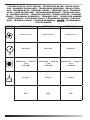
TECHNICAL DATA - DATI TECNICI - TECHNISCHE DATEN - DATOS TÉCNI-
COS - DONNÉES TECHNIQUES - TECHNISCHE GEGEVENS - DADOS TÉCNI-
COS - TEKNISKE DATA - TEKNISET TIEDOT - TEKNISKE DATA - TEKNISKA
DATA - DANE TECHNICZNE - ТЕХНИЧЕСКИЕ ДАННЫЕ - TECHNICKÉ ÚDA-
JE - MŰSZAKI ADATOK - TEHNIČNI PODATKI - TEKNİK VERİLER - TEHNIČKI
PODACI - TECHNINIAI DUOMENYS - TEHNISKIE DATI - TEHNILISED ANDMED
- DATE TEHNICE - TECHNICKÉ ÚDAJE - ТЕХНИЧЕСКИ ДАННИ - ТЕХНІЧНІ
ДАНІ - TEHNIČKI PODACI - ΤΕΧΝΙΚΑ ΔΕΔΟΜΕΝΑ - 技术参数 - ТЕХНИКАЛЫ
КРСЕТКІШТЕР
MODEL BCM 19AB BCM 19AL BCM 19AU
7,2 A
7,2 A
7,2 A
IP55 IP55 IP55

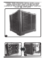
PICTURES - FIGURE - ABBILDUNGEN - FIGURAS - FIGURES - FIGUREN
- FIGURAS - FIGURER - KUVAT - FIGURER - FIGURER - ILUSTRACJE
- ИЛЛЮСТРАЦИИ - OBRÁZKY - ÁBRÁK - SLIKE - ŞEKİLLER - SLIKE -
ILIUSTRACIJOS - ATTĒLI - JOONISED - IMAGINI - OBRÁZKY - СХЕМИ - ДАНІ
- ΕΙΚΟΝΕΣ - 图示 - СУРЕТТЕМЕЛЕР
2
1
2
3
3
3
3
4
4
6
5 55
6
7
9
8
90°
90 cm
15 cm
65 cm
50 cm
90°
90 cm
15 cm
65 cm
50 cm
65 cm
50 cm
65 cm
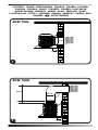
BCM 19AB
BCM 19AB

PICTURES - FIGURE - ABBILDUNGEN - FIGURAS - FIGURES - FIGUREN
- FIGURAS - FIGURER - KUVAT - FIGURER - FIGURER - ILUSTRACJE
- ИЛЛЮСТРАЦИИ - OBRÁZKY - ÁBRÁK - SLIKE - ŞEKİLLER - SLIKE -
ILIUSTRACIJOS - ATTĒLI - JOONISED - IMAGINI - OBRÁZKY - СХЕМИ - ДАНІ
- ΕΙΚΟΝΕΣ - 图示 - СУРЕТТЕМЕЛЕР
2
1
2
3
3
3
3
4
4
6
5 55
6
7
9
8
90°
90 cm
15 cm
65 cm
50 cm
90°
90 cm
15 cm
65 cm
50 cm
65 cm
50 cm
65 cm
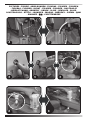
BCM 19AL
BCM 19AU

PICTURES - FIGURE - ABBILDUNGEN - FIGURAS - FIGURES - FIGUREN
- FIGURAS - FIGURER - KUVAT - FIGURER - FIGURER - ILUSTRACJE
- ИЛЛЮСТРАЦИИ - OBRÁZKY - ÁBRÁK - SLIKE - ŞEKİLLER - SLIKE -
ILIUSTRACIJOS - ATTĒLI - JOONISED - IMAGINI - OBRÁZKY - СХЕМИ - ДАНІ
- ΕΙΚΟΝΕΣ - 图示 - СУРЕТТЕМЕЛЕР
2
1
2
3
3
3
3
4
4
6
5 55
6
7
9
8
90°
90 cm
15 cm
65 cm
50 cm
90°
90 cm
15 cm
65 cm
50 cm
65 cm
50 cm
65 cm

en
it
de
es
fr
nl
pt
da
no
sv
pl
ru
cs
hu
sl
tr
hr
lt
lv
et
ro
sk
bg
uk
bs
el
zh
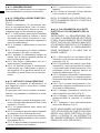
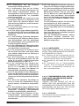
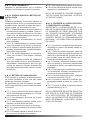
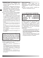
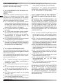
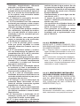
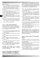
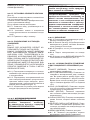
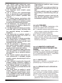
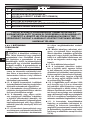
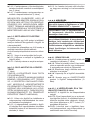
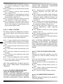
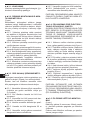
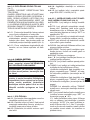
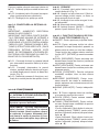
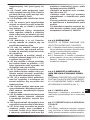
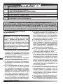
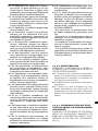
►►1. INFORMATION ON
SAFETY
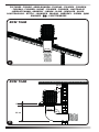
(Pic. 1)
IMPORTANT: This appliance is not
suitable for use by persons (including
children) with reduced physical, sensory
or mental capacities or who lack experi-
ence or knowledge unless supervised
by a person responsible for their safety.
Children must be supervised to make
sure they do not play with the appliance.
connection, water connection, use and
maintenance of the cooler, comply with
all local regulations and standards in
force.
-
sonnel.
-
ify, ventilate or remove dust.
or serious injuries, install the cooler at
-
machines, electrical panels, etc.) or from
combustion fumes (hoods, chimney
-
damage.
make sure that the cooler, the power
supply cable, the control panel, etc., are
perfectly dry, in order to prevent any
with wet hands).
stable and level structure, so as to pre-
vent any risk (the structure and the plugs
must be adequate to support the weight
of the cooler).
-
ommended between the cooler and walls
or other items is 0.5 m.
2
3
/h
of air supplied to the cooler must be
provided (always ensure an exchange
of air within the cooled environment).
In the event of forced air ventilation, the
amount extracted should be less than
can be combined with natural ventila-
tion.
nameplate, using cables of suitable sec-
tion (the supply voltage must not vary
the nameplate).
properly.
-
spected when connecting to the mains.
We recommend using a suitable residual
current device (see nameplate).
PARAGRAPH SUMMARY
1... SAFETY INFORMATION
2... UNPACKING
3... ASSEMBLY AND INSTALLATION
(ONLY FOR QUALIFIED PERSONNEL)
4... OPERATION
5... CLEANING AND MAINTENANCE
6... CONTROL PANEL ERROR DIAGNOSTICS
7... TROUBLESHOOTING

en
it
de
es
fr
nl
pt
da
no
sv
pl
ru
cs
hu
sl
tr
hr
lt
lv
et
ro
sk
bg
uk
bs
el
zh
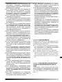
-
pressure of the water supply is higher, a
pressure reducer must be installed.
clean water.
coverage to protect from weathering, in
order to preserve the cooler over time.
or adjust the cooler and the electricity or
water supply after installation, if it is not
air vents of the cooler, in order to pre-
-
age, do not let dust, dirt or other materi-
als come into contact with the cooler.
with ambient temperatures between
-
-
downs, when the temperatures drop to
and the pipes that supply water to the
cooler.
you handle or service the cooler (use
personal protective equipment in order
-
aged, it must be replaced by a technical
support centre to prevent any risk.
-
tential damage caused by the movement
of vehicles, pedestrians, weathering and
heat sources.
-
tions, disconnect the power supply and
contact the technical support centre.
supply, when it is not used for a medium
to long term period.
tank must come from an aqueduct. If it is
not possible to draw from an aqueduct,
the water introduced must be subjected
to a sanitation treatment, according to
-We recommend using water with a hard-
-The cooler tank must be emptied and
sanitised periodically depending on the
use.
-The cooling pad surfaces must be pe-
riodically inspected and sanitised de-
pending on the use.
-
ucts that comply with European regula-
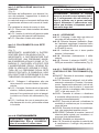
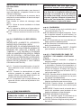
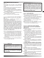
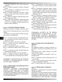
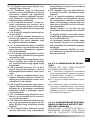
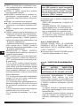
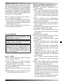
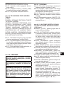
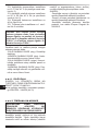
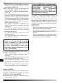
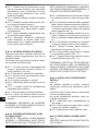
►►2. UNPACKING
IMPORTANT: IT IS STRICTLY FORBIDDEN
TO STACK TWO OR MORE COOLERS.
2.1. Remove all packaging material used to
pack and deliver the cooler and dispose of it
in compliance with current standards.
2.2. Remove all items from the packaging.
2.3. Check for any damage incurred during
transport. If the cooler appears damaged,
immediately inform the dealer from whom it
was purchased.
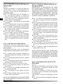
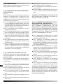
►►3. ASSEMBLY AND INSTALLA-
TION (ONLY FOR QUALIFIED PER-
SONNEL)
NOTE: TO ACCESS THE INTERNAL PARTS
OF THE COOLER, REMOVE THE SCREWS
AND EVAPORATION PANELS, PLACE
THEM ON THE SIDES OF THE COOLER
(Pic. 2).
Handle the cooler with the utmost care, mov-
ing it horizontally.
-
(Pic. 3)
During installation, the electrical connection,
water connection, use and maintenance of
the cooler, comply with all local regulations
and standards in force.
3.2.1. The cooler must be installed on a sta-
ble and level structure, so as to prevent any

en
it
de
es
fr
nl
pt
da
no
sv
pl
ru
cs
hu
sl
tr
hr
lt
lv
et
ro
sk
bg
uk
bs
el
zh
risk (the structure and the plugs must be ad-
equate to support the weight of the cooler).
3.2.2. Install the cooler in well ventilated ar-
eas.
3.2.3. The cooler can only be installed out-
side (on the roof or on the wall).
3.2.4. -
es, heat sources and possible sparks, in or-
der to prevent serious damage.
3.2.5. Do not drill screws or tie rods into the
cooler during installation.
3.2.6. The minimum installation distance
between the cooler and walls or other ob-
jects is 0.5 m (ensure suitable spaces for
maintenance around the cooler).
By connecting a conduit to the cooler, the out-
going air can be carried to where cooling is
required.
It is crucial for the entire ducting conduit to be
designed and structured correctly.
3.3.1. Use conduits of suitable section (the
average air speed inside the conduit is 3-6
m/s).
3.3.2. The ducting should be as short as
possible.
3.3.3. The pipes must be installed at a max-
imum of 4 m above the ground.
3.3.4. Do not install the duct with elbow
bends.
3.3.5. The maximum length of the conduit
is 20 m.
3.3.6. Up to four reductions can be installed
within the conduit.
3.3.7.
3.3.8. -
eral conduits.
NOTE: WE RECOMMEND USING CON-
DUITS MADE OF GALVANISED SHEET
METAL, PLASTIC OR FIBREGLASS.
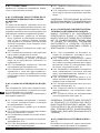
-
IMPORTANT: THE POWER SUPPLY AND
CONNECTION LINE MUST BE INSTALLED
BY A QUALIFIED TECHNICIAN USING SUIT-
ABLE DEVICES AND INSTRUMENTS, IN
ACCORDANCE WITH NATIONAL REGULA-
TIONS AND THE STANDARDS IN FORCE.
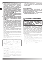
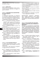
3.4.1. By removing the screws on the side
of the cooler you have access to the interior
of the appliance (Pic. 2).
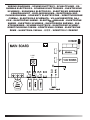
3.4.2. Feed the electrical cables (power ca-
ble, control panel cable and solenoid valve
cable) through the hole near the electrical
panel on the bottom of the cooler (Pic. 4).
3.4.3. Only connect and power the cooler
the nameplate and with cables of suitable
section.
3.4.4. For proper operation it is crucial to
connect the earth to the cooler properly.
3.4.5. Connect the control panel by using
(Pic. 5).
3.4.6. Connect the temperature/humidity
probe cable to the control panel (Pic. 5).
3.4.7. Connect the solenoid valve cable to
the electrical panel (Pic. 5).
NOTE: MAKE SURE THE POLARITIES ARE
FOLLOWED WHEN CONNECTING TO THE
MAINS. WE RECOMMEND USING A SUIT-
ABLE RESIDUAL CURRENT DEVICE (SEE
NAMEPLATE).
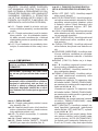
(Pic. 6)
At the base of the cooler, to drain water from
the tank, the cooler is equipped with a drain
valve.
At the time of purchase, the drain valve comes
in the kit supplied.
To install the valve you must:
3.5.1. Remove the nut installed at the base
of the valve.
3.5.2. Insert the valve into its seat (located
at the base of the cooler).
3.5.3. Screw the nut back onto the valve.
(Pic. 7)
IMPORTANT: ONLY FEED THE COOLER
WITH CLEAN WATER.
IMPORTANT: THE COOLER CAN WITH-
STAND A MAXIMUM WATER INLET PRES-
SURE OF 3 BAR. THE PIPES AND FITTINGS

en
it
de
es
fr
nl
pt
da
no
sv
pl
ru
cs
hu
sl
tr
hr
lt
lv
et
ro
sk
bg
uk
bs
el
zh
USED FOR THE WATER SUPPLY MUST BE
OF ADEQUATE SECTION AND STRUC-
TURE (IF THE PRESSURE OF THE WATER
MAINS IS HIGH, WE RECOMMEND USING
A PRESSURE REDUCER AND A METAL
MESH PIPE).
3.6.1. Connect the cooler to the water
solenoid valve.
3.6.2. Connect the solenoid valve to the
electrical panel, by feeding the electrical
cables through the hole near the electrical
panel on the bottom of the cooler (Pic. 4).
3.6.3. Make sure that there are no water
leaks in the circuit before commissioning.
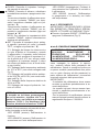
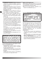
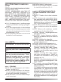
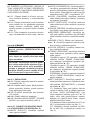
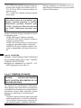
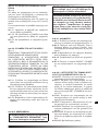
►►4. OPERATION
cooler.
-
vent failures or other anomalies.
-
tem is earthed correctly. Connection to
the mains must be made in compliance
Only power the cooler with the voltage
-
plate.
Connect the hose of the water supply
-
Check that there are no leaks during
refuelling.
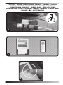
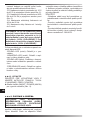
4.1.4. Supply electricity to the cooler.
4.1.5. Press ON/OFF / POWER to turn on
the cooler (Pic. 9).
AUTO: Activates the automatic cooling cy-
cle. During operation, the appliance will al-
ternate the cooling cycle with the cleaning
cycle. The cleaning cycle time must be set
via the “SET” function and the “P1” sub-
menu.
COOL: Activates or disables the cooling
mode (ventilation does not start immedi-
ately).
VENT: Activates or disables the ventilation
mode.
CLEAN: Activates the cleaning mode, which
will take a few minutes.
REVERSE: Reverses the direction of rota-
tion of the fan, to introduce or remove air
from the room.
SWING: Mode not available.
the control panel clock.
CLOCK: It is used to set the control panel
clock.
TIMING: Enables to activate or deactivate
-Delayed switch-on: With the cooler
switched on, press the “TIMING” button to
-
tons).
switched on, press the “TIMING” button to
-
tons).
NOTE: To reset the settings of the “TIMING”
mode, disconnect the power supply to the
cooler.
-P1: Setting the time between one cleaning
cycle and the next, when the cooler is set
to the “AUTO” function (you can choose to
set the cleaning cycle from 3 to 72 hours,
however, we always recommend setting the
value to the lowest number of hours in order
to prevent any risk).
-P2: Room temperature setting from 10°C
to 40°C (with probe disconnected see Pic.
5).
-P3: Room relative humidity setting from
20% Rh to 40% Rh (with probe connected
see Pic. 5).
-P4: Electric frequency setting from 40Hz to
60Hz.

en
it
de
es
fr
nl
pt
da
no
sv
pl
ru
cs
hu
sl
tr
hr
lt
lv
et
ro
sk
bg
uk
bs
el
zh
-P5: Cleaning time setting from 1 minute to
5 minutes.
NOTE: When the control panel shows a
means that the tank is empty and must
-
activate the acoustic beep, deactivate
During operation, a status LED lights up on
the control panel:
-GREEN LED (on): Cooler in operation.
-ORANGE LED (on): Cooler switching on
with low water level.
problems between the control panel and
cooler.
stand-by with low water level.
IMPORTANT: TO DISCHARGE THE WATER
FROM THE TANK, ENABLE THE “COOL”
FUNCTION BEFORE SWITCH-OFF.
►
cooler (Pic. 9).
►►5. CLEANING AND MAINTE-
NANCE
Depending on the environment where the
performance of the cooler. We therefore
recommend cleaning (never clean with a high
pressure water jet) the outside of the cooler
with a soft cloth, removing any obstructions
from the air vents.
IMPORTANT:
-The cooler tank must be emptied and sani-
tised periodically depending on the use.
-The cooling pad surfaces must be periodi-
cally inspected and sanitised depending on
the use.
-For sanitation operations, biocidal prod-
ucts that comply with European regulation
no. 582/2012 must be used.

en
it
de
es
fr
nl
pt
da
no
sv
pl
ru
cs
hu
sl
tr
hr
lt
lv
et
ro
sk
bg
uk
bs
el
zh
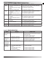
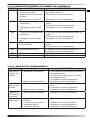
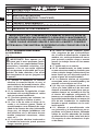
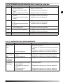
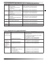
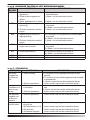
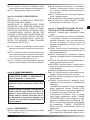
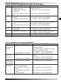
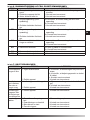
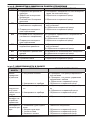
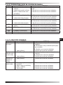
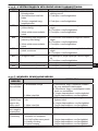
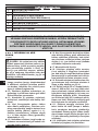
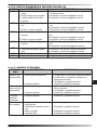
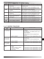
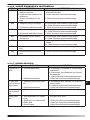
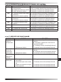
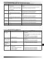
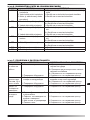
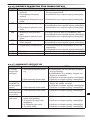
►►►6. CONTROL PANEL ERROR DIAGNOSTICS
ERROR CAUSE SOLUTION
E1
1. Electronic equipment over-
heating
2. Defective electronic equip-
ment
3. Blocked or faulty motor
1. Disconnect the cooler from the electricity
mains for a few minutes
2. Contact the support centre
3. Contact the support centre
E2
1. Inadequate voltage (over-
voltage)
2. Faulty electrical connec-
tions
1a. Check your system is powered correctly
1b. Contact the support centre
2. Contact the support centre
E3
1. Inadequate voltage (under-
voltage)
2. Faulty electrical connec-
tions
1a. Check your system is powered correctly
1b. Contact the support centre
2. Contact the support centre
E4
1. Faulty electrical motor con-
nections
1a. Check your system is powered correctly
1b. Contact the support centre
E7
1. Cooler blocked
1b. Contact the support centre
F4
1. Communication problems 1. Contact the support centre
F6
1. Communication problems 1. Contact the support centre
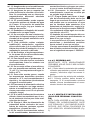
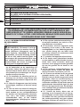
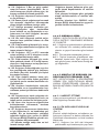
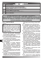
►►7. TROUBLESHOOTING
FAULT CAUSE SOLUTION
The control
panel does not
function
1. No power supply
2. Defective equipment
1a. Make sure that the device is powered
1b. Check that the control panel is connect-
ed to the cable
1c. Contact a support centre
2. Contact a support centre
There is no
very low
1. Obstructed air vents
2. Defective equipment
1a. Remove any objects from the air vent
1b. Contact a support centre
2. Contact a support centre
The device
does not re-
spond to the
commands
1. Defective equipment 1. Contact a support centre
The device
leaks water
1. The water supply pipe is
loose
2. The water drain is dirty
3. The tank leaks
4. The panel is dripping
2. Contact a support centre
3. Contact a support centre
4. Contact a support centre

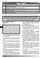
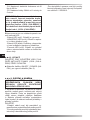
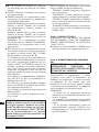
►►1. INFORMAZIONI SULLA
SICUREZZA
(Fig. 1)
IMPORTANTE: Questo apparecchio
non è adatto all’uso da parte di persone
sensoriali e mentali ridotte, o inesperte,
a meno che non vengano supervisionate
da una persona responsabile per la loro
-
trollati, per assicurarsi che non giochino
con l’apparecchio.
-
sione elettrica, la connessione idrica,
-
alla normativa vigente.
-
-
-
nare la polvere.
-
-
di calore (camini, fuoco, ecc.), da scin-
tille (saldatrici, quadri elettrici, ecc.) o
da fumi di combustione (cappe, canne
fumarie, ecc.).
rischio o gravi guasti.
-
-
mandi, ecc., siano perfettamente asciut-
guasti (non operare mai con le mani ba-
gnate).
-
to su una struttura stabile e livellata, in
modo da evitare ogni rischio (la struttu-
ra e i tasselli devono essere adeguati a
-
tore e pareti o altri oggetti è 0,5 m.
2
3
/h di aria forni-
ricambio d’aria all’interno dell’ambiente
-
-
-
-
-
rispetto al valore dichiarato sulla targa
dati).
opportunamente collegato a massa.
SOMMARIO PARAGRAFI
1... INFORMAZIONI SULLA SICUREZZA
2... DISIMBALLAGGIO
3... ASSEMBLAGGIO E INSTALLAZIONE
(SOLO PER PERSONALE QUALIFICATO)
4... FUNZIONAMENTO
5... PULIZIA E MANUTENZIONE
6... DIAGNOSTICA ERRORI SUL PANNELLO DI CONTROLLO
7... ANOMALIE DI FUNZIONAMENTO
en
it
de
es
fr
nl
pt
da
no
sv
pl
ru
cs
hu
sl
tr
hr
lt
lv
et
ro
sk
bg
uk
bs
el
zh

polarità in fase di collegamento alla rete
-
adeguato (vedi targa dati).
pressione massima d’ingresso acqua di
-
ca dovesse essere maggiore, è necessa-
rio installare un riduttore di pressione.
-
tore solamente con acqua pulita.
-
-
-
tore nel tempo.
-
della rete elettrica o idrica dopo l’instal-
-
modo da prevenire ogni rischio.
-
tare che polvere, sporco o altri materiali,
-
scatore con temperature ambiente com-
-
do le temperature si abbassano a circa <
-
io e i condotti che riforniscono l’acqua al
-
-
schio).
danneggiato, deve essere sostituito dal
prevenire ogni rischio.
-
-
mento di veicoli, pedoni, agenti atmosfe-
rici e fonti di calore.
elettrica e contattare il centro di centro
-
per un medio-lungo periodo.
-
venire da un acquedotto. Nel caso non
sia possibile attingere da un acquedotto,
l’acqua introdotta deve essere sottopo-
-
-
-
vono essere impiegati prodotti bioci-
►►2. DISIMBALLAGGIO
IMPORTANTE: È ASSOLUTAMENTE VIE-
TATO IMPILARE A DUE O PIÙ UNITÀ I RAF-
FRESCATORI.
2.1. Rimuovere tutti i materiali di imballag-
gio usati per confezionare e spedire il raf-
frescatore e smaltire secondo le norme vi-
genti.
2.2. Estrarre tutti gli articoli dall’imballo.
2.3. Controllare eventuali danni subiti du-
danneggiato, informare immediatamente il
concessionario presso il quale è stato ac-
quistato.
►►3. ASSEMBLAGGIO E INSTAL-
LAZIONE (SOLO PER PERSONALE
QUALIFICATO)
NOTA: PER ACCEDERE ALLE PARTI IN-
TERNE DEL RAFFRESCATORE, RIMUO-
VERE LE VITI E I PANNELLI EVAPORATIVI,
POSIZIONATI SUI FIANCHI DEL RAFFRE-
SCATORE (Fig. 2).
en
it
de
es
fr
nl
pt
da
no
sv
pl
ru
cs
hu
sl
tr
hr
lt
lv
et
ro
sk
bg
uk
bs
el
zh

cura, spostandolo in posizione orizzontale.
(Fig. 3)
Durante l’installazione, la connessione elet-
trica, la connessione idrica, l’uso e la manu-
ordinanze locali ed alla normativa vigente.
3.2.1.
su una struttura stabile e livellata, in modo
da evitare ogni rischio (la struttura e i tas-
selli devono essere adeguati a supportare il
3.2.2.
ventilate.
3.2.3.
solo all’esterno (sul tetto o a parete).
3.2.4.
camini, fonti di calore e possibili scintille, al
tiranti durante l'installazione.
3.2.6. La distanza minima di installazione,
altri oggetti è 0,5 m (garantire attorno al raf-
frescatore gli spazi idonei per la manuten-
zione).
-
È importante che l’intero condotto di canaliz-
zazione, sia progettato e strutturato in modo
corretto.
3.3.1. Utilizzare condotti di adeguata sezio-
ne (la velocità media dell’aria all’interno del
condotto è 3-6 m/s).
3.3.2. La canalizzazione deve essere più
corta possibile.
3.3.3. Le tubazioni devono essere installate
al massimo a 4 m di altezza dal suolo.
3.3.4. Evitare curve a gomito del condotto.
3.3.5. La lunghezza massima del condotto
deve essere 20 m.
3.3.6. Si devo installare al massimo quattro
riduzioni all’interno del condotto.
3.3.7. Le giunzioni del tubo devono essere
3.3.8.
in più condotti e sotto condotti.
NOTA: SI CONSIGLIA DI UTILIZZARE CON-
DOTTI IN LAMIERA ZINCATA, PLASTICA O
VETRO RESINA.
IMPORTANTE: LA REALIZZAZIONE DEL-
LA LINEA DI ALIMENTAZIONE ELETTRICA
E DELL’ALLACCIAMENTO DEVE ESSERE
EFFETTUATA DA UN TECNICO ABILITATO,
UTILIZZANDO DISPOSITIVI E STRUMENTI
IDONEI, SECONDO LA REGOLAMENTA-
ZIONE NAZIONALE E IN LINEA CON LE
NORME VIGENTI.
3.4.1. -
frescatore, si ha accesso all’interno dell’ap-
parecchio (Fig. 2).
3.4.2. Far passare i cavi elettrici (cavo di ali-
mentazione, il cavo del pannello di controllo
e il cavo dell’elettrovalvola) attraverso il foro
posizionato vicino al pannello elettrico sul
3.4.3. Collegare e
solamente con tensione e frequenza speci-
sezione.
3.4.4. Per il corretto funzionamento è fon-
damentale collegare correttamente la mes-
3.4.5. Collegare il pannello di controllo, tra-
(Fig. 5).
3.4.6. Collegare il cavo della sonda di tem-
peratura/umidità al pannello di controllo
(Fig. 5).
3.4.7. Collegare il cavo dell’elettrovalvola
al pannello elettrico (Fig. 5).
NOTA: ASSICURARSI CHE SIANO RISPET-
TATE LE POLARITÀ IN FASE DI COLLEGA-
MENTO ALLA RETE ELETTRICA. SI CON-
SIGLIA L’UTILIZZO DI UN INTERRUTTO-
RE MAGNETOTERMICO DIFFERENZIALE
ADEGUATO (VEDI TARGA DATI).
en
it
de
es
fr
nl
pt
da
no
sv
pl
ru
cs
hu
sl
tr
hr
lt
lv
et
ro
sk
bg
uk
bs
el
zh

(Fig. 6)
-
qua dal serbatoio, l’apparecchio è dotato di
una valvola di scarico.
La valvola di scarico al momento dell’acquisto
è posizionata all’interno del corredo di vendi-
ta.
Per installare la valvola di scarico si deve:
3.5.1. Rimuovere il dado installato alla base
della valvola.
3.5.2. Inserire la valvola nell’apposita sede
3.5.3. Riavvitare il dado sulla valvola.
(Fig. 7)
IMPORTANTE: ALIMENTARE IL RAFFRE-
SCATORE SOLO CON ACQUA PULITA.
IMPORTANTE: IL RAFFRESCATORE PUÒ
SUPPORTARE UNA PRESSIONE MASSI-
MA D’INGRESSO ACQUA DI 3 BAR. LE TU-
BAZIONI E I RACCORDI UTILIZZATI PER
L’ALIMENTAZIONE IDRICA, DEVONO ES-
SERE DI ADEGUATE SEZIONE E STRUT-
TURA (SE LA PRESSIONE DELLA RETE
IDRICA È ELEVATA, SI CONSIGLIA L’USO
DEL RIDUTTORE DI PRESSIONE E DI UNA
TUBAZIONE CON MAGLIA METALLICA).
-
valvola.
3.6.2. Collegare l’elettrovalvola al pannello
elettrico, facendo passare i cavi elettrici at-
traverso il foro posizionato vicino al pannel-
4).
-
dite d’acqua del circuito, prima della messa
in funzione.
►►4. FUNZIONAMENTO
pulita, per evitare guasti o altre anomalie.
messa a terra del vostro impianto elettri-
co. Il collegamento alla rete elettrica va
-
-
cata sulla targa dati.
Collegare il tubo della rete idrica al
Rifornire d’acqua il serbatoio. Quan-
do il serbatoio raggiunge il massimo livello,
un galleggiante bloccherà automaticamen-
durante il rifornimento.
4.1.4. -
scatore.
4.1.5. Premere il pulsante ON/OFF / PO-
ON/OFF: Permette di accendere o spegne-
-
scamento automatico. Durante il funziona-
mento, l’apparecchio alternerà il ciclo di raf-
frescamento al ciclo di pulizia. Il tempo del
ciclo di pulizia va impostato dalla funzione
“SET“ e dal sotto menu “P1“.
COOL: Permette di attivare o disattivare
non parte immediatamente).
VENT: Permette di attivare o disattivare la
modalità di ventilazione per la movimenta-
zione dell’aria.
CLEAN: Permette di attivare la modalità pu-
lizia, che impiegherà qualche minuto.
REVERSE: Permette di invertire il senso di
rotazione della ventola, per immettere o ri-
muovere l’aria dall’ambiente.
SWING: Modalità non disponibile.
-
la ventilazione e l’orologio del pannello di
controllo.
en
it
de
es
fr
nl
pt
da
no
sv
pl
ru
cs
hu
sl
tr
hr
lt
lv
et
ro
sk
bg
uk
bs
el
zh

CLOCK: Permette di impostare l’orologio
del pannello di controllo.
TIMING: Permette di attivare o disattivare
la modalità accensione o spegnimento ritar-
dato.
-
so, preme il pulsante “TIMING“, per impo-
stare l’accensione ritardata (agire sui pul-
-
ceso, preme il pulsante “TIMING“, per im-
postare lo spegnimento ritardato (agire sui
NOTA: Per resettare le impostazioni della
modalità “TIMING“, togliere l’alimentazione
SET: Permette di impostare alcuni settag-
-P1: Settaggio del tempo che intercorre tra
un ciclo di pulizia e il successivo, quando
-
clo di pulizia da 3 a 72 ore, ad ogni modo,
consigliamo di impostare sempre il valore
-
re ogni rischio).
-P2: Settaggio della temperatura ambiente
da 10°C a 40°C (con sonda collegata vedi
Fig. 5).
-P3: Settaggio dell’umidità relativa ambien-
te da 20% Rh a 40% Rh (con sonda colle-
gata vedi Fig. 5).
-P4: Settaggio della frequenza elettrica da
40 Hz a 60 Hz.
-P5: Settaggio del tempo di pulizia da 1 mi-
nuto a 5 minuti.
NOTA: Quando sul pannello di controllo
si accende un led rosso accompagnato
-
batoio è vuoto e va riempito nuovamente
Durante il funzionamento sul pannello di con-
trollo si accende un led di stato:
funzione.
accensione con livello dell’acqua basso.
-LED VERDE (lampeggiante): Problemi di
comunicazione tra il pannello di controllo e
in spegnimento o in stand-by con livello
dell’acqua basso.
IMPORTANTE: PER SCARICARE L’ACQUA
DAL SERBATOIO, PRIMA DELLO SPEGNI-
MENTO, ATTIVARE LA FUNZIONE ”COOL”.
►Premere il pulsante ON/OFF / POWER per
►►5. PULIZIA E MANUTENZIONE
viene impiegato, la polvere, lo sporco,
un panno morbido (assolutamente non pulire
con un getto d’acqua ad alta pressione) la
eventuali ostruzioni delle prese d’aria.
IMPORTANTE:
-
conda dell’utilizzo.
-
-
conda dell’utilizzo.
essere impiegati prodotti biocidi conformi al
regolamento europeo n° 582/2012.
en
it
de
es
fr
nl
pt
da
no
sv
pl
ru
cs
hu
sl
tr
hr
lt
lv
et
ro
sk
bg
uk
bs
el
zh

►►►6. DIAGNOSTICA ERRORI SUL PANNELLO DI CONTROLLO
ERRORE CAUSA SOLUZIONE
E1
1. Surriscaldamento apparec-
chiatura elettronica
2. Apparecchiatura elettronica
difettosa
3. Motore bloccato o guasto
per qualche minuto
2. Rivolgersi al centro di assistenza
3. Rivolgersi al centro di assistenza
E2
1. Tensione non adeguata (so-
vratensione)
2. Collegamenti elettrici difet-
tosi
-
pianto
1b. Rivolgersi al centro di assistenza
2. Rivolgersi al centro di assistenza
E3
1. Tensione non adeguata (sot-
to tensione)
2. Collegamenti elettrici difet-
tosi
-
pianto
1b. Rivolgersi al centro di assistenza
2. Rivolgersi al centro di assistenza
E4
1. Collegamenti elettrici del
motore difettosi
-
pianto
1b. Rivolgersi al centro di assistenza
E7
1b. Rivolgersi al centro di assistenza
F4
1. Problemi di comunicazione 1. Rivolgersi al centro di assistenza
F6
1. Problemi di comunicazione 1. Rivolgersi al centro di assistenza
►►7. ANOMALIE DI FUNZIONAMENTO
ANOMALIA CAUSA SOLUZIONE
Il pannello di
controllo non
funziona
1. Mancanza alimentazione
2. Apparecchiatura difettosa
1a. Controllare che il dispositivo sia alimen-
tato elettricamente
1b. Controllare che il pannello di controllo
sia collegato al cavo
1c. Contattare il centro di assistenza
2. Contattare il centro di assistenza
d’aria o è mol-
to basso
1. Ostruzione delle prese d’aria
2. Apparecchiatura difettosa
1a. Rimuovere eventuali oggetti dalla presa
d’aria
1b. Contattare il centro di assistenza
2. Contattare il centro di assistenza
Il dispositivo
non risponde
ai comandi
1. Apparecchiatura difettosa 1. Contattare il centro di assistenza
Il dispositivo
perde acqua
1. Il tubo di fornitura idrica è
allentato
2. Lo scarico acqua è sporco
3. Il serbatoio perde
4. Il pannello gocciola
1. Avvitare il raccordo
2. Contattare il centro di assistenza
3. Contattare il centro di assistenza
4. Contattare il centro di assistenza
en
it
de
es
fr
nl
pt
da
no
sv
pl
ru
cs
hu
sl
tr
hr
lt
lv
et
ro
sk
bg
uk
bs
el
zh
La pagina si sta caricando...
La pagina si sta caricando...
La pagina si sta caricando...
La pagina si sta caricando...
La pagina si sta caricando...
La pagina si sta caricando...
La pagina si sta caricando...
La pagina si sta caricando...
La pagina si sta caricando...
La pagina si sta caricando...
La pagina si sta caricando...
La pagina si sta caricando...
La pagina si sta caricando...
La pagina si sta caricando...
La pagina si sta caricando...
La pagina si sta caricando...
La pagina si sta caricando...
La pagina si sta caricando...
La pagina si sta caricando...
La pagina si sta caricando...
La pagina si sta caricando...
La pagina si sta caricando...
La pagina si sta caricando...
La pagina si sta caricando...
La pagina si sta caricando...
La pagina si sta caricando...
La pagina si sta caricando...
La pagina si sta caricando...
La pagina si sta caricando...
La pagina si sta caricando...
La pagina si sta caricando...
La pagina si sta caricando...
La pagina si sta caricando...
La pagina si sta caricando...
La pagina si sta caricando...
La pagina si sta caricando...
La pagina si sta caricando...
La pagina si sta caricando...
La pagina si sta caricando...
La pagina si sta caricando...
La pagina si sta caricando...
La pagina si sta caricando...
La pagina si sta caricando...
La pagina si sta caricando...
La pagina si sta caricando...
La pagina si sta caricando...
La pagina si sta caricando...
La pagina si sta caricando...
La pagina si sta caricando...
La pagina si sta caricando...
La pagina si sta caricando...
La pagina si sta caricando...
La pagina si sta caricando...
La pagina si sta caricando...
La pagina si sta caricando...
La pagina si sta caricando...
La pagina si sta caricando...
La pagina si sta caricando...
La pagina si sta caricando...
La pagina si sta caricando...
La pagina si sta caricando...
La pagina si sta caricando...
La pagina si sta caricando...
La pagina si sta caricando...
La pagina si sta caricando...
La pagina si sta caricando...
La pagina si sta caricando...
La pagina si sta caricando...
La pagina si sta caricando...
La pagina si sta caricando...
La pagina si sta caricando...
La pagina si sta caricando...
La pagina si sta caricando...
La pagina si sta caricando...
La pagina si sta caricando...
La pagina si sta caricando...
La pagina si sta caricando...
La pagina si sta caricando...
La pagina si sta caricando...
La pagina si sta caricando...
La pagina si sta caricando...
La pagina si sta caricando...
La pagina si sta caricando...
La pagina si sta caricando...
La pagina si sta caricando...
La pagina si sta caricando...
La pagina si sta caricando...
La pagina si sta caricando...
La pagina si sta caricando...
La pagina si sta caricando...
La pagina si sta caricando...
La pagina si sta caricando...
La pagina si sta caricando...
La pagina si sta caricando...
La pagina si sta caricando...
La pagina si sta caricando...
La pagina si sta caricando...
La pagina si sta caricando...
La pagina si sta caricando...
La pagina si sta caricando...
La pagina si sta caricando...
La pagina si sta caricando...
La pagina si sta caricando...
La pagina si sta caricando...
La pagina si sta caricando...
La pagina si sta caricando...
La pagina si sta caricando...
La pagina si sta caricando...
La pagina si sta caricando...
La pagina si sta caricando...
La pagina si sta caricando...
La pagina si sta caricando...
La pagina si sta caricando...
La pagina si sta caricando...
La pagina si sta caricando...
-
 1
1
-
 2
2
-
 3
3
-
 4
4
-
 5
5
-
 6
6
-
 7
7
-
 8
8
-
 9
9
-
 10
10
-
 11
11
-
 12
12
-
 13
13
-
 14
14
-
 15
15
-
 16
16
-
 17
17
-
 18
18
-
 19
19
-
 20
20
-
 21
21
-
 22
22
-
 23
23
-
 24
24
-
 25
25
-
 26
26
-
 27
27
-
 28
28
-
 29
29
-
 30
30
-
 31
31
-
 32
32
-
 33
33
-
 34
34
-
 35
35
-
 36
36
-
 37
37
-
 38
38
-
 39
39
-
 40
40
-
 41
41
-
 42
42
-
 43
43
-
 44
44
-
 45
45
-
 46
46
-
 47
47
-
 48
48
-
 49
49
-
 50
50
-
 51
51
-
 52
52
-
 53
53
-
 54
54
-
 55
55
-
 56
56
-
 57
57
-
 58
58
-
 59
59
-
 60
60
-
 61
61
-
 62
62
-
 63
63
-
 64
64
-
 65
65
-
 66
66
-
 67
67
-
 68
68
-
 69
69
-
 70
70
-
 71
71
-
 72
72
-
 73
73
-
 74
74
-
 75
75
-
 76
76
-
 77
77
-
 78
78
-
 79
79
-
 80
80
-
 81
81
-
 82
82
-
 83
83
-
 84
84
-
 85
85
-
 86
86
-
 87
87
-
 88
88
-
 89
89
-
 90
90
-
 91
91
-
 92
92
-
 93
93
-
 94
94
-
 95
95
-
 96
96
-
 97
97
-
 98
98
-
 99
99
-
 100
100
-
 101
101
-
 102
102
-
 103
103
-
 104
104
-
 105
105
-
 106
106
-
 107
107
-
 108
108
-
 109
109
-
 110
110
-
 111
111
-
 112
112
-
 113
113
-
 114
114
-
 115
115
-
 116
116
-
 117
117
-
 118
118
-
 119
119
-
 120
120
-
 121
121
-
 122
122
-
 123
123
-
 124
124
-
 125
125
-
 126
126
-
 127
127
-
 128
128
-
 129
129
-
 130
130
-
 131
131
-
 132
132
-
 133
133
-
 134
134
-
 135
135


Master BCM19 AB AL AU E2020 Manuale del proprietario
- Tipo
- Manuale del proprietario
in altre lingue
Documenti correlati
-
Master BCB19 E2020 Manuale del proprietario
-
Dantherm BCB 19 Manuale utente
-
Master BCF230 4140.377 R19E2 Manuale del proprietario
-
-
-
-
-
-
-

