
Rif. +080001052 - rel. 1.0 - 27.01.2014
Il display remoto KD201Y001 per centralina di regolazione consente il monitoraggio, la configurazio-
ne e la gestione dell’impianto da utilizzare con il modulo di regolazione KPM30 o KPM31.
Il software applicativo è residente soltanto sul modulo di controllo KPM30 o KPM31. Il terminale non
ha bisogno di nessun software aggiuntivo in fase di utilizzo.
Inoltre il terminale offre un ampio range di temperatura di funzionamento (-20T60 °C) e nella versio-
ne ad incasso il frontale garantisce un elevato grado di protezione (IP65).
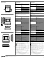
Montaggio a parete
Il montaggio a parete del terminale prevede l’iniziale fissaggio del retrocontenitore A (Fig. 1), per
mezzo di una scatola standard a 3 moduli per interruttori.
• Fissare il retrocontenitore alla scatola tramite le viti a testa bombata presenti all’interno dell’imballo;
• collegare il cavo telefonico proveniente dalla scheda KPM30 o KPM31 all’apposito connettore
(RJ12) posto sul retro del terminale;
• appoggiare il frontale al retrocontenitore e fissare il tutto utilizzando le viti a testa svasata presenti
all’interno dell’imballo;
• infine, installare la cornice a scatto.
Collegamento elettrico
Collegare il cavo telefonico proveniente dalla centralina KPM30 o KPM31 all’apposito connettore (RJ12)
posto sul retro del terminale.
Il bus deve essere cablato in modalità “entra-esci”. La lunghezza della rete non deve superare i 500 m.
Installare una resistenza da 120 Ω tra RX/RT+ e RX/RT- del primo e dell’ultimo elemento collegato
alla rete bus. Il cavo bus deve essere installato in guaine dedicate, separate e distanziate dai cavi di
potenza.
Segnalazione guasti
Se il terminale rivela lo stato di fuori linea della scheda KPM30 o KPM31 a cui è stato associato can-
cella il display e visualizza il messaggio: I/O Board xx fault.
Mentre, se il terminale non riceve nessun segnale di rete, cancella il display e visualizza il seguente
messaggio:
NO LINK
.
Visualizzazione stato rete e versione del firmware
Premendo contemporaneamente i tasti di configurazione (↓↑↵ per almeno 10 secondi (solo in
modalità pLAN), si visualizza la maschera di Fig. 3. La schermata in Fig. 2 esemplifica lo stato della
rete pLAN, visualizzando quanti e quali dispositivi sono collegati, e con quale indirizzo.
Legenda:
: controllore KPM30 o KPM31 attivo in rete
: terminale attivo in rete
: nessun dispositivo collegato
Tramite i tasti ↓↑↵ è possibile visualizzare la versione del firmware residente nel terminale.
Per uscire dalla procedura NetSTAT premere il tasto ↵.
Regolazione contrasto LCD
I tasti + Prg + ↓↑consentono la regolazione del contrasto.
The KD201Y001 remote display, allows monitoring, configuration and full management of the plant
controlled by KPM30 or KPM31 control modules.
The application software resides
on KPM30 or KPM31 control module.
therefore the terminal does
not require any additional software for operation.
Furthermore, the terminals feature a wide operating temperature range (-20T60 °C) and in the built-in
version, the front panel ensures a high index of protection (IP65).
Wall-mounted version
The wall-mounting of the terminal first requires the back piece of the container A (Fig. 1) to be fit-
ted, using a standard three-module switch box.
•
Fasten the back piece to the box using the rounded-head screws supplied in the packaging;
•
Connect the telephone cable from the KPM30 o KPM31 board to the connector provided (RJ12)
on the rear of the terminal;
•
Rest the front panel on the back piece and fasten the parts together using the flush-head screws
supplied in the packaging;
•
Finally, fit the click-on frame.
Electrical connection
Connect the telephone cable from the KPM30 or KPM31 module to the proper connector (RJ12) on
the back of the terminal.
The bus must be wired in “enter-exit” mode. The length of the network must not exceed 500 m.
Install a 120 Ω resistor between RX/RT+ and RX/RT- of the first and last element connected to the
bus network. The bus cable must be installed in dedicated sheaths, separated and spaced from the
power cables.
Fault signals
If the terminal detects the off-line status of the KPM30 o KPM31 board it is associated with, the
display shows the message:
I/O Board xx fault.
On the other hand, if the terminal receives no signal from the network, the display shows the fol-
lowing message:
NO LINK
.
Displaying the status of the network and firmware version
Pressing the configuration buttons (↓↑↵) together for at least 10 seconds (in pLAN mode only),
displays the screen shown in Fig. 3. The screen shown in Fig. 2 provides an example of the status of
the pLAN, displaying which and how many devices are connected, and the corresponding addres-
ses.
Key:
:
KPM30 o KPM31 controllers active in network
:
terminals active in network
:
no device connected
The ↓↑↵ buttons can be used to display the version of the firmware resident in the terminal.
To exit the NetSTAT procedure, press ↵.
Contrast adjustment
Use + Prg + ↓↑ buttons to adjust the contrast.
A
Fig. 1
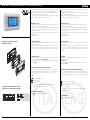
Terminale versione montaggio a parete
Wall mounting terminal
Display remoto per KPM30 - KPM31 /
Remote display for KPM30 - KPM31
KD201Y001
Assegnazione lista terminali privati e condivisi /
Assigning the list of private and shared terminals
Fig. 3
Fig. 2

12/2018
Caratteristiche tecniche
Display
Tipo: grafico FSTN
Retroilluminazione: LED verdi o LED bianchi (comandabile da “software applica-
tivo”)
a seconda del codice
Risoluzione in grafica: 132x64 pixel
Modi testo: 8 righe x 22 colonne (font 5x7 e 11x15 pixel)
4 righe x 11 colonne (font 11x15 pixel)
oppure modi misti
Altezza carattere: 3,5 mm (font 5x7 pixel)
7,5 mm (font 11x15 pixel)
Dimensione area attiva: 66x32 mm
Dimensione area visiva: 72x36 mm
LED tastiera / buzzer
2 programmabili da “software applicativo” di colore rosso e arancio (tasti Prg e Alarm)
4 di colore verde, asserviti al comando backlight dell’LCD (tasti ↓↑↵ e Esc)
Alimentazione
Tensione: alimentazione da KPM30 o KPM31 tramite connettore tele-
fonico oppure da sorgente esterna 18/30 Vdc protetta da
fusibile esterno da 250 mAT
Potenza assorbita massima: 1,2 W
Distanze massime
Lunghezza massima rete pLAN: 500 m con cavo AWG22 a coppie schermate
Distanza KPM30 o KPM31 terminale: 50 m con cavo telefonico
500 m con cavo AWG22 a coppie schermate e TCONN6J000
Nota: per raggiungere la lunghezza massima utilizzare una
tipologia a bus con diramazioni che non superano i 5 m.
Materiali
Frontale trasparente: policarbonato trasparente
Retrocontenitori grigio antracite (pare-
te/incasso):
policarbonato +ABS
Tastiera: gomma siliconica
Vetrino trasparente/cornice: policarbonato trasparente
Autoestinguenza: V0 su frontale trasparente e retrocontenitori
HB su tastiera siliconica e particolari restanti
Generali
Grado di protezione: IP65 con montaggio a pannello
IP40 con montaggio a parete
UL type 1
Condizioni di funzionamento: -20T60 °C, 90% U.R. non condensante
Condizioni di immagazzinamento: -20T70 °C, 90% U.R. non condensante
Classe e struttura del software: A
Classificazione secondo il grado di
protezione contro le scosse elettriche:
Da incorporare in apparecchiature di classe I o II
PTI dei materiali di isolamento: PCB: PTI 250; insulation material PTI 175
Periodo delle sollecitazioni elettriche: lungo
Categoria di resistenza al calore e al
fuoco:
D
Immunità contro le sovratensioni: Categoria II
Inquinamento ambientale: 2
82
31
156
Technical specifications
Display
Type: FSTN graphic
Backlighting: green or white LEDs (controlled by “application software”),
depending on the code
Graphic resolution: 132x64 pixels
Text mode: 8 rows x 22 columns (font sizes 5x7 and 11x15 pixels)
4 rows x 11 columns (font size 11x15 pixels)
or mixed modes
Character height: 3.5 mm (font size 5x7 pixels)
7.5 mm (font size 11x15 pixels)
Size of active area: 66x32 mm
Size of display area: 72x36 mm
Keypad LEDs / Buzzer
2 programmable by “application software”, red and orange (Prg and Alarm buttons)
4 green LEDs, used as backlighting for LCD (↓↑↵ and Esc buttons)
Buzzer (optional - models *z0, *X0)
Power supply
Voltage: power supply from KPM30 o KPM31 through telephone
cable or external source
18/30 Vdc protected with 2 250 mAT fuse
Maximum power input: 1.2 W (green backlight), 0,8 W (white backlight)
Maximum distances
Maximum pLAN length: 500 m with AWG22 twisted pair cable
KPM30 o KPM31 terminal distance: 50 m with telephone cable
500 m with AWG22 twisted pair cable and TCONN6J000
Note: to reach the maximum length, use a bus layout,
with branches not exceeding 5 m.
Materials
Transparent front panel: transparent polycarbonate
Charcoal grey container back piece
(wall/built-in):
polycarbonate +ABS
Keypad: silicon rubber
Transparent cover glass/frame: transparent polycarbonate
Self-extinguishing classification: V0 for transparent front panel and back piece
HB for silicon keypad and remaining parts
Others
Index of protection: IP65 for panel mounting
IP40 for wall mounting
UL type 1
Operating conditions: -20T60 °C, 90% r.H. non-condensing
Storage conditions: -20T70 *C, 90% r.H. non-condensing
Software class and structure: A
Classification according to
protection against electric shock: To be integrated into class 1 or 2 devices
PTI of insulating materials: PCB: PTI 250; insulation material PTI 175
Period of electric stress across insula-
ting parts:
long
Category of resistance to fire and heat: D
Immunity against voltage surges: Category II
Environmental pollution: 2
Dimensioni / Dimensions
134
Ø 4
34.5
dima di foratura
drilling template
127x69 mm
Ø 4
Fig. 4
Fig. 5
Fig. 6
GIACOMINI S.p.A.
Via per Alzo 39, 28017 San Maurizio d’Opaglio (NO) Italy - www.giacomini.com
AVVERTENZE PER IL CORRETTO SMALTIMENTO DEL PRODOTTO
Questo prodotto rientra nel campo di applicazione della Direttiva 2012/19/UE riguardante la gestione dei
rifiuti di apparecchiature elettriche ed elettroniche (RAEE).
L’apparecchio non deve essere eliminato con gli scarti domestici in quanto composto da diversi materiali
che possono essere riciclati presso le strutture adeguate.
Informarsi attraverso l’autorità comunale per quanto riguarda l’ubicazione delle piattaforme ecologiche atte a
ricevere il prodotto per lo smaltimento ed il suo successivo corretto riciclaggio.
Si ricorda, inoltre, che a fronte di acquisto di apparecchio equivalente, il distributore è tenuto al ritiro gratuito
del prodotto da smaltire. Il prodotto non è potenzialmente pericoloso per la salute umana e l’ambiente, ma se
abbandonato nell’ambiente impatta negativamente sull’ecosistema.
Leggere attentamente le istruzioni prima di utilizzare l’apparecchio per la prima volta.
Si raccomanda di non usare assolutamente il prodotto per un uso diverso da quello a cui è stato destinato, essen-
doci pericolo di shock elettrico se usato impropriamente.
Il simbolo del bidone barrato, presente sull’etichetta posta sull’apparecchio, indica la rispondenza di tale prodotto
alla normativa relativa ai rifiuti di apparecchiature elettriche ed elettroniche.
L’abbandono nell’ambiente dell’apparecchiatura o lo smaltimento abusivo della stessa sono puniti dalla legge.
IMPORTANT INFORMATION FOR CORRECT DISPOSAL OF THE PRODUCT
This product falls into the scope of the Directive 2012/19/EU concerning the management of Waste
Electrical and Electronic Equipment (WEEE).
This product shall not be dispose in to the domestic waste as it is made of different materials that have
to be recycled at the appropriate facilities.
Inquire through the municipal authority regarding the location of the ecological platforms to receive the product
for disposal and its subsequent correct recycling.
Furthermore, upon purchase of an equivalent appliance, the distributor is obliged to collect the product for
disposal free of charge. The product is not potentially dangerous for human health and the environment, but if
abandoned in the environment can have negative impact on the environment.
Read carefully the instructions before using the product for the first time.
It is recommended that you do not use the product for any purpose rather than those for which it was intended,
there being a danger of electric shock if used improperly.
The crossed-out wheeled dustbin symbol, on the label on the product, indicates the compliance of this product
with the regulations regarding Waste Electrical and Electronic Equipment.
Abandonment in the environment or illegal disposal of the product is punishable by law.
-
 1
1
-
 2
2


in altre lingue
Documenti correlati
Altri documenti
-
Carel PGD1000F00 Guida Rapida
-
-
-
-
-
Danfoss MCX15B2 - MCX20B2 programmable controller Guida d'installazione
-
-
-
MOBVOI Ticwatch Pro 5 Guida utente
-