
cod. +050001045 rel. 1.2 - 05.02.2004
PGD0000I00
pCO display grafico /
pCO Graphic Display
Vi ringraziamo per la scelta fatta, sicuri che sarete soddisfatti del vostro acquisto.
Il display grafico pGD è un dispositivo elettronico, compatibile con i precedenti terminali della linea PCOI/PCOT, che
consente la completa gestione della grafica tramite la visualizzazione di icone (definite a livello di sviluppo software
applicativo) e la gestione di font internazionali di due dimensioni: 5x7 e 11x15 pixel.
Il software applicativo è residente soltanto sulla scheda pCO, il terminale non ha bisogno di nessun software
aggiuntivo in fase di utilizzo.
Inoltre il terminale offre un ampio range di temperatura di funzionamento (-20T60 °C) e il frontale garantisce un
elevato grado di protezione (IP55).
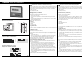
Montaggio a pannello (cod. PGD0000I00)
Questi terminali sono stati progettati per montaggio a pannello (Fig. 1); la dima di foratura deve avere le dimensioni
di 173x154 mm. Per l’installazione seguire le istruzioni riportate di seguito:
• asportare la cornice estetica a scatto;
• inserire la parte plastica contenente display e schede elettroniche sulla parete forata anteriore del pannello,
facendo attenzione che la guarnizione sul lembo inferiore del frontale sia bene in appoggio con la parte anteriore
del pannello;
• praticare sul pannello 4 fori del diametro di 2,5 mm, in corrispondenza esatta con i fori presenti sullo strumento;
• inserire le viti di fissaggio presenti in dotazione, scegliendo le viti autofilettanti o automaschianti a seconda del
materiale del pannello (plastico o metallico).
Effettuare quindi i collegamenti elettrici previsti.
Legenda Fig. 1:
1 cornice esterna;
2 pannello (spessore massimo 6 mm);
3 terminale;
4 guarnizione isolante.
Collegamento elettrico
Collegare il cavo telefonico (cod. S90CONN00*) proveniente dalla scheda pCO all’apposito connettore (RJ12) posto
sul retro del terminale.
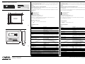
Configurazione indirizzo
È possibile configurare l’indirizzo del terminale solo dopo aver fornito alimentazione allo stesso tramite il connettore
telefonico RJ12 (il valore preimpostato in fabbrica è 32).
Per entrare in modalità configurazione premere contemporaneamente i tasti
↓+↑+
enter (sempre presenti in tutte le
versioni) per almeno 5 secondi; verrà visualizzata la maschera di Fig. 2 con il cursore lampeggiante nell’angolo in
alto a sinistra:
• Per modificare l’indirizzo del terminale (display address setting) premere una volta il tasto ”enter”: il cursore si
sposterà sul campo indirizzo (nn);
• Tramite i tasti
↓↑
selezionare il valore voluto, e confermare ripremendo il tasto enter. Se il valore selezionato è
diverso da quello memorizzato precedentemente apparirà la maschera di Fig. 3 e il nuovo valore verrà
memorizzato nella memoria permanente del display.
Se si imposta il campo nn al valore 0, il terminale comunicherà con la scheda pCO usando il protocollo
“punto-punto” (non pLAN) e il campo “I/O Board address: xx” scompare in quanto privo di significato.
pCO: assegnazione lista terminali privati e condivisi
A questo punto, se fosse necessario modificare la lista dei terminali associata ad ogni singola scheda pCO, si
dovrà seguire la seguente procedura:
• Entrare nella modalità configurazione con i tasti
↓+↑
+enter, come descritto nel paragrafo precedente;
• Premere il tasto enter fino a che il cursore si posiziona sul campo xx (I/O board address) Fig. 2;
• Tramite i tasti
↓↑
scegliere l’indirizzo della scheda pCO desiderata. I valori selezionabili saranno solo quelli
delle schede pCO effettivamente in linea. Se la rete pLAN non funziona correttamente, oppure non è
presente nessuna scheda pCO, non sarà possibile modificare il campo che mostrerà solo “—”;
• Premendo ancora una volta il tasto ”enter” verranno visualizzate in sequenza le maschere di Fig. 4;
• Anche qui il tasto ”enter” muove il cursore da un campo all’altro e i tasti
↓↑
cambiano il valore del campo
corrente. Il campo P:xx mostra l’indirizzo della scheda selezionata; nell’esempio di figura è stata selezionata la 12.
Per uscire dalla procedura di configurazione e memorizzare i dati selezionare il campo “OK ?” impostare
Yes e confermare con il tasto enter.
I campi della colonna “Adr” rappresentano gli indirizzi dei terminali associati alla scheda pCO di indirizzo
12, mentre la colonna Priv/Shared indica il tipo di terminale.
Attenzione: i terminali della linea pGD non possono essere configurati come “Sp” (shared printer) in quanto
privi dell’uscita stampante.
Se il terminale rimane inattivo (nessun tasto premuto) per più di 30 secondi esce automaticamente dalla
procedura di configurazione senza memorizzare gli eventuali cambiamenti.
Thank you for your choice. We trust you will be satisfied with your purchase.
The pGD graphic display is an electronic device that is compatible with the previous PCOI/PCOT line terminals; it
allows complete management of graphics by the display of icons (defined at an application software development
level), as well as the management of international fonts, in two sizes: 5x7 and 11x15 pixels.
The application software resides on the pCO board, and therefore the terminal does not require any additional
software for operation.
Furthermore, the terminals feature a wide operating temperature range (-20T60 °C) and the front panel ensures a
high index of protection (IP55).
Panel-mounted version (code PGD0000I00)
These terminals have been designed for panel installation (Fig. 1); the drilling template must measure 173x154 mm.
For installation, follow the instructions provided below:
• remove the click-on decorative frame;
• insert the plastic part containing the display and electronic boards on the drilled front face of the panel, making
sure that the gasket on the lower edge of the front panel rests correctly against the front of the panel;
• make 4 holes, diameter 2.5 mm, in the panel, in exact correspondence with the holes present on the instrument;
• insert the fastening screws supplied, choosing the self-tapping or thread-cutting screws, according to the material
the panel is made from (plastic or metallic).
Make the envisaged electrical connections.
Fig. 1 Key:
1 outside frame;
2 panel (maximum thickness 6 mm);
3 terminal;
4 insulating gasket.
Electrical connection
Connect the telephone cable (code S90CONN00*) from the pCO board to the connector provided (RJ12) on the
rear of the terminal.
Configuring the address
The address of the terminal can be configured only after having connected the power supply, using the RJ12
telephone jack (the factory default value is 32).
To access configuration mode, press the
↓+↑+
enter buttons (present on all versions) together and hold them for at
least 5 seconds; the screen shown in Fig. 2 will be displayed, with the cursor flashing in the top left corner:
• To change the address of the terminal (display address setting), press the enter button once: the cursor will move
to the address field (nn);
• Use the
↓↑
buttons to select the desired value, and confirm by pressing enter again. If the value selected is
not the same as the one saved previously, the screen shown in Fig. 3 will be displayed, and the new value
will be saved to the permanent memory.
If the field nn is set to 0, the terminal will communicate with the pCO board using “point-to-point” protocol (not pLAN)
and the field “I/O Board address: xx” will not be displayed, as it has no meaning.
pCO: assigning the list of private and shared terminals
At this point, if the list of terminals associated with each individual pCO board needs to be modified, proceed as
follows:
• Access configuration mode using the
↓+↑+
enter buttons, as described in the previous paragraph;
• Press the “enter” button until the cursor moves to the field xx (I/O board address) Fig. 2;
• Use the
↓↑
buttons to select the pCO board in question. The values available correspond to the pCO boards that
are effectively on line. If the pLAN network is not working correctly, or if no pCO board is present, the field cannot
be modified, and the symbol “—” will be displayed;
• Pressing “enter” again displays the screens shown in Fig. 4, in sequence;
• Here too, the “enter” button moves the cursor from one field to the next, and the
↓↑
buttons change the value of
the current field. The field P:xx shows the address of the board selected; in the example shown in the figure, the
value 12 has been selected.
To exit the configuration procedure and save the data, select the field “OK ?”, choose Yes and confirm by pressing
“enter”.
The fields in the “Adr” column represent the addresses of the terminals associated with the pCO board that has
address 12, while the Priv/Shared column indicates the type of terminal.
Note: the pGD terminals cannot be configured as “Sp” (shared printer), as they have no printer port.
If the terminal remains inactive (no button is pressed) for more than 30 seconds, the configuration procedure is exi-
ted automatically, without saving any changes.
Configurazione indirizzo /
Configuring the address
Fig. 2
Fig. 3
Fig. 4
me
nu
I/O
set
prog.
?
info
154
173
2
3
1
4
Fig. 1
Montaggio ad incasso /
Panel mounting
Assegnazione lista terminali privati e condivisi /
Assigning the list of private and shared terminals

CAREL S.p.A.
Via dell’Industria, 11 - 35020 Brugine - Padova (Italy)
Tel. (+39) 0499716611 – Fax (+39) 0499716600
http://www.carel.com – e-mail: [email protected]
CAREL si riserva la possibilità di apportare modifiche o cambiamenti ai propri prodotti senza alcun preavviso.
CAREL reserves the right to modify the features of its products without prior notice.
cod. +050001045 rel. 1.2 - 05.02.2004
Segnalazione guasti
Se il terminale rivela lo stato di fuori linea della scheda pCO a cui è stato associato cancella il display e visualizza il
messaggio:
I/O Board xx fault
.
Mentre, se il terminale non riceve nessun segnale di rete, cancella il display e visualizza il seguente messaggio:
NO LINK.
Visualizzazione stato rete e versione del firmware
Premendo contemporaneamente i tasti di configurazione (
↓
+
↑
+enter) per almeno 10 secondi (solo in modalità
pLAN), si visualizza la maschera di Fig. 5.
La schermata in Fig. 5 esemplifica lo stato della rete pLAN, visualizzando quanti e quali dispositivi sono collegati, e
con quale indirizzo.
Legenda:
: controllore pCO attivo in rete
: terminale attivo in rete
: nessun dispositivo collegato
Ad esempio la Fig. 5 rappresenta:
controllori pCO attivi in rete con indirizzo: 1, 2, 25
terminali attivi in rete con indirizzo: 3, 4, 15, 26.
Tramite i tasti
↓ ↑
è possibile visualizzare la versione del firmware residente nel terminale (Fig. 6):
Per uscire dalla procedura NetSTAT premere il tasto ”enter”.
Regolazione contrasto LCD
I tasti +
Prg
+
↓ ↑
consentono la regolazione del contrasto.
Caratteristiche tecniche
Display
Tipo: grafico FSTN
Retroilluminazione: LED verdi (comandabile da “software applicativo”)
Risoluzione in grafica: 120x32 pixel
Modi testo: 4 righe x 20 colonne (font 5x7 e 11x15 pixel)
2 righe x 10 colonne (font 11x15 pixel)
oppure modi misti
Altezza carattere: 4,5 mm (font 5x7 pixel)
9 mm (font 11x15 pixel)
Dimensione area attiva: 71,95x20,75 mm
Dimensione area visiva: 76x25,2 mm
Alimentazione
Tensione: alimentazione da pCO tramite connettore telefonico oppure da
sorgente esterna 18/30 Vdc protetta da fusibile esterno da 250 mAT
Potenza assorbita massima: 1,5 W
Distanze massime
Lunghezza massima rete pLAN: 500 m con cavo AWG22 a coppie schermate
Distanza pCO terminale: 50 m con cavo telefonico
500 m con cavo AWG22 a coppie schermate e TCONN6J000
Nota: per raggiungere la lunghezza massima utilizzare una
tipologia a bus con diramazioni che non superano i 5 m
Materiali
Contenitore: blend di ABS+policarbonato
Tastiera: gomma siliconica+ABS
Autoestinguenza: V0
Generali
Grado di protezione: IP55
UL type 1
Condizioni di funzionamento: -20T60 °C, 90% U.R. non condensante
Condizioni di immagazzinamento: -20T70 °C, 90% U.R. non condensante
Classe e struttura del software: A
Classificazione secondo il grado di
protezione contro le scosse elettriche: Da incorporare in apparecchiature di classe I o II
PTI dei materiali di isolamento: 250 V
Periodo delle sollecitazioni elettriche: lungo
Categoria di resistenza al calore e al fuoco: D
Categoria (immunità contro le sovratensioni): I
Inquinamento ambientale: normale
Dimensioni /
Dimensions
dima di foratura
drilling template
173 x 154mm
124mm
181.5mm
15mm
4.25mm
Ø 2.5mm
15mm
154mm
173mm
4
on/off alarm enter
menu I/O set prog.
?
info
Graphic
202
43
53
177
Fig. 7
Fig. 8
Fault signals
If the terminal detects the off-line status of the pCO board it is associated with, the display shows the message:
I/O Board xx fault
.
On the other hand, if the terminal receives no signal from the network, the display shows the following message:
NO LINK.
Displaying the status of the network and firmware version
Pressing the configuration buttons (
↓+↑+
enter) together for at least 10 seconds (in pLAN mode only), displays the
screen shown in Fig. 5.
The screen shown in Fig. 5 provides an example of the status of the pLAN, displaying which and how many devices
are connected, and the corresponding addresses.
Key:
: pCO controller active in network
: terminals active in network
: no device connected
The example in Fig. 5 represents:
pCO controllers active in network, addresses: 1, 2, 25
terminals active in network, addresses: 3, 4, 15, 26.
The
↓ ↑
buttons can be used to display the version of the firmware resident in the terminal (Fig. 6):
To exit the NetSTAT procedure, press “enter”.
Contrast adjustment
Use the
+
Prg
+
↓ ↑
buttons to adjust the contrast
Technical specifications
Display
Type: FSTN graphic
Backlighting: Greed LEDs (controlled by “application software”)
Graphic resolution: 120x32 pixels
Text mode: 4 rows x 20 columns (font sizes 5x7 and 11x15 pixels)
2 rows x 10 columns (font size 11x15 pixels)
or mixed mode
Character height: 4.5 mm (font size 5x7 pixels)
9 mm (font size 11x15 pixels)
Size of active area: 71.95x20.75 mm
Size of display area: 76x25.2 mm
Power supply
Voltage: power supply from pCO through telephone cable or external
source 18/30 Vdc protected with a 250 mAT fuse
Maximum power input: 1.5 W
Maximum distances
Maximum pLAN length: 500 m with AWG22 twisted pair cable
pCO terminal distance: 50 m with telephone cable
500 m with AWG22 twisted pair cable and TCONN6J000
Note: to reach the maximum length, use a
bus layout, with branches not exceeding 5 m
Materials
Case: combination of ABS and polycarbonate
Keypad: silicon rubber + ABS
Self-extinguishing rating: V0
Other
Index of protection: IP55
UL type 1
Operating conditions: -20T60 °C, 90% r.H. non-condensing
Storage conditions: -20T70 °C, 90% r.H. non-condensing
Software class and structure: A
Classification according to
protection against electric shock: To be integrated into class 1 or 2 devices
PTI of insulating materials: 250 V
Period of electric stress across insulating parts: long
Category of resistance to fire and heat: D
Category (immunity against voltage surges): I
Environmental pollution: normal
Fig. 5
Fig. 6
Assegnazione lista terminali privati e condivisi
Assigning the list of private and shared terminals
-
 1
1
-
 2
2


in altre lingue
- English: Carel PGD0000I00 Quick start guide
Documenti correlati
-
Carel PGD1000F00 Guida Rapida
-
-
-
-
-
-
-
-
-