Yamaha 2002 YFM400FWA Manuale utente
- Categoria
- Motociclette
- Tipo
- Manuale utente
Questo manuale è adatto anche per

YFM400FWA
(
P
)
5GH3-AE2
SUPPLEMENTARY
SERVICE MANUAL
2002


FOREWORD
This Supplementary Service Manual has been prepared to introduce new service and new data for
the YFM400FWA(P) 2002. For complete information on service procedures, it is necessary to use
this Supplementary Service Manual together with the following manual.
YFM400FWA(M) 2000 SERVICE MANUAL: 5GH3-AE1
YFM400FWA(P) 2002
SUPPLEMENTARY
SERVICE MANUAL
2001 by Yamaha Motor Co., Ltd.
First Edition, June 2001
All rights reserved.
Any reproduction or unauthorized use
without the written permission of
Yamaha Motor Co., Ltd.
is expressly prohibited.

EB001000
NOTICE
This manual was produced by the Yamaha Motor Company primarily for use by Yamaha dealers
and their qualified mechanics. It is not possible to include all the knowledge of a mechanic in one
manual, so it is assumed that anyone who uses this book to perform maintenance and repairs on
Yamaha machine has a basic understanding of the mechanical ideas and the procedures of
machine repair. Repairs attempted by anyone without this knowledge are likely to render the
machine unsafe and unfit for use.
Yamaha Motor Company, Ltd. is continually striving to improve all its models. Modifications and sig-
nificant changes in specifications or procedures will be forwarded to all authorized Yamaha dealers
and will appear in future editions of this manual where applicable.
N
OTE:
Designs and specifications are subject to change without notice.
IMPORTANT INFORMATION
Particularly important information is distinguished in this manual by the following notations.
The Safety Alert Symbol means ATTENTION! BECOME ALERT! YOUR
SAFETY IS INVOLVED!
Failure to follow WARNING instructions could result in severe injury or death
to the machine operator, a bystander or a person inspecting or repairing the
machine.
A CAUTION indicates special precautions that must be taken to avoid dam-
age to the machine.
A NOTE provides key information to make procedures easier or clearer.
WARNING
CAUTION:
N
O
TE:

EB002000
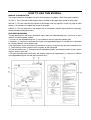
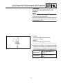
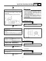
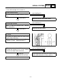
HOW TO USE THIS MANUAL
MANUAL ORGANIZATION
This manual consists of chapters for the main categories of subjects. (See “Illustrated symbols”)
1st title
1
: This is the title of the chapter with its symbol in the upper right corner of each page.
2nd title
2
: This title indicates the section of the chapter and only appears on the first page of each
section. It is located in the upper left corner of the page.
3rd title
3
: This title indicates a sub-section that is followed by step-by-step procedures accompa-
nied by corresponding illustrations.
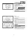
EXPLODED DIAGRAMS
To help identify parts and clarify procedure steps, there are exploded diagrams at the start of each
removal and disassembly section.
1. An easy-to-see exploded diagram
4
is provided for removal and disassembly jobs.
2. Numbers
5
are given in the order of the jobs in the exploded diagram. A number that is enclosed
by a circle indicates a disassembly step.
3. An explanation of jobs and notes is presented in an easy-to-read way by the use of symbol marks
6
. The meanings of the symbol marks are given on the next page.
4. A job instruction chart
7
accompanies the exploded diagram, providing the order of jobs, names
of parts, notes in jobs, etc.
5. For jobs requiring more information, the step-by-step format supplements
8
are given in addition
to the exploded diagram and the job instruction chart.

EB003000
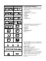
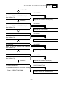
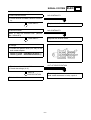
ILLUSTRATED SYMBOLS
Illustrated symbols
1
to
9
are printed on the
top right of each page and indicate the subject
of each chapter.
1
General information
2
Specifications
3
Periodic checks and adjustments
4
Engine
5
Carburetion
6
Drive train
7
Chassis
8
Electrical
9
Troubleshooting
Illustrated symbols
0
to
F
are used to identify
the specifications appearing in the text.
0
Filling fluid
A
Lubricant
B
Special tool
C
Torque
D
Wear limit, clearance
E
Engine speed
F
Ω
, V, A
Illustrated symbols
G
to
M
in the exploded
diagrams indicate the types of lubricants and
lubrication points.
G
Apply engine oil
H
Apply gear oil
I
Apply molybdenum disulfide oil
J
Apply wheel bearing grease
K
Apply lightweight lithium soap base grease
L
Apply molybdenum disulfide grease
M
Apply silicon grease
Illustrated symbols
N
to
O
in the exploded
diagrams indicate where to apply a locking
agent
N
and when to install a new part
O
.
N
Apply the locking agent (LOCTITE
)
O
Replace
12
34
56
78
90
AB
CD
EF
GHI
J
NO
GEN
INFO
SPEC
CHK
ADJ
ENG
CARB
DRIV
CHAS
–+
ELEC
TRBL
SHTG
T
R
.
.
E
G
M
B
LS
M
S
KLM
LT
New

CONTENTS
SPECIFICATIONS
............................................................................................1
GENERAL SPECIFICATIONS ..................................................................1
MAINTENANCE SPECIFICATIONS .........................................................2
ENGINE ................................................................................................2
ELECTRICAL ........................................................................................4
CABLE ROUTING .....................................................................................5
PERIODIC CHECKS AND ADJUSTMENTS
..................................................15
INTRODUCTION .....................................................................................15
PERIODIC MAINTENANCE/LUBRICATION INTERVALS ......................15
CHASSIS .................................................................................................17
ADJUSTING THE REAR BRAKE LIGHT SWITCH .............................17
ENGINE
..........................................................................................................18
CYLINDER HEAD ...................................................................................18
CYLINDER HEAD INSTALLATION ....................................................18
RECOIL STARTER AND CDI MAGNETO ..............................................21
TRANSMISSION .....................................................................................23
ELECTRICAL
.................................................................................................25
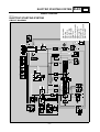
ELECTRIC STARTING SYSTEM ............................................................25
CIRCUIT DIAGRAM ............................................................................25
TROUBLESHOOTING ........................................................................26
SIGNAL SYSTEM ...................................................................................29
CIRCUIT DIAGRAM ............................................................................29
CHECKING THE SIGNAL SYSTEM ...................................................31
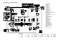
YFM400FWA(P) 2002 WIRING DIAGRAM


– 1 –
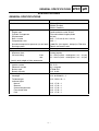
SPEC
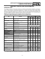
GENERAL SPECIFICATIONS
SPECIFICATIONS
GENERAL SPECIFICATIONS
Item Standard
Model code: 5GHL: (CDN)
5GHM: (Europe)
5GHN: (Oceania)
Engine:
Engine type Liquid-cooled 4-stroke, SOHC
Cylinder arrangement Forward-inclined single cylinder
Displacement 401 cm³
Bore
×
stroke 84.5
×
71.5 mm (3.33
×
2.81 in)
Compression ratio 10.5 : 1
Standard compression pressure (at sea level) 1,400 kPa (14.0 kg/cm², 203 psi) at 750 r/min
Starting system Electric and recoil starter
Lubrication system: Wet sump
Tire pressure (cold tire):
Maximum load* 210 kg (463 Ib)
Off-road riding front 22 ~ 28 kPa (0.22 ~ 0.28 kg/cm², 3.2 ~ 4.1 psi)
rear 22 ~ 28 kPa (0.22 ~ 0.28 kg/cm², 3.2 ~ 4.1 psi)
*Load in total weight of rider accessories
Electrical:
Ignition system DC. C.D.I.
Generator system A.C. magneto
Battery type YTX20L-BS
Battery capacity 12 V 18 AH
Bulb wattage
×
quantity:
Headlight 12 V 30 W/30 W
×
2
Tail/brake light 12 V 5 W/21 W
×
1
Indicator lights
Neutral 12 V 1.7 W
×
1
Reverse 12 V 1.7 W
×
1
Coolant temperature 12 V 1.7 W
×
1
Four-wheel drive 12 V 1.7 W
×
1
Park 12 V 1.7 W
×
1

– 2 –
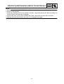
SPEC
MAINTENANCE SPECIFICATIONS
MAINTENANCE SPECIFICATIONS
ENGINE
Item Standard Limit
Cylinder:
Bore size 84.500 ~ 84.510 mm
(3.3268 ~ 3.3272 in)
84.600 mm
(3.3307 in)
Taper limit ---- 0.05 mm
(0.0016 in)
Out of round limit ---- 0.01 mm
(0.0004 in)
Measuring point 40 mm (1.57 in) ----
Cam chain:
Cam chain type/No. of links DID SCR-0409 SDH/116 ----
Cam chain adjustment method Automatic ----
Rocker arm/rocker arm shaft:
Bearing inside diameter 12.000 ~ 12.018 mm
(0.4724 ~ 0.4731 in)
12.078 mm
(0.4755 in)
Shaft outside diameter 11.981 ~ 11.991 mm
(0.4717 ~ 0.4721 in)
11.951 mm
(0.4705 in)
Arm-to-shaft clearance 0.009 ~ 0.037 mm
(0.0004 ~ 0.0015 in)
0.08 mm
(0.0031 in)
Piston:
Piston to cylinder clearance 0.040 ~ 0.065 mm
(0.0016 ~ 0.0026 in)
0.15 mm
(0.0059 in)
Piston size “D” 84.445 ~ 84.460 mm
(3.3246 ~ 3.3252 in)
----
Measuring point “H” 5 mm (0.20 in) ----
Piston off-set 0.5 mm (0.0200 in) ----
Off-set direction Intake side ----
Piston pin bore inside diameter 20.004 ~ 20.015 mm
(0.7876 ~ 0.7880 in)
20.045 mm
(0.7892 in)
Piston pin outside diameter 19.993 ~ 20.000 mm
(0.7871 ~ 0.7874 in)
19.973 mm
(0.7863 in)
*
H
D

– 3 –
SPEC
MAINTENANCE SPECIFICATIONS
Automatic centrifugal clutch:
Clutch shoe thickness 1.5 mm (0.06 in) 1.0 mm
(0.04 in)
Clutch-in revolution 1,960 ~ 2,240 r/min ----
Clutch-stall revolution 3,300 ~ 3,900 r/min ----
Carburetor:
I.D.mark 5GH9 11 ----
Main jet (M.J) #130 ----
Main air jet (M.A.J) #50 ----
Jet needle (J.N) 5EP3-55-3 ----
Needle jet (N.J) P-0M ----
Pilot air jet (P.A.J.1) #80 ----
Pilot air jet (P.A.J.2) 1.3 ----
Pilot outlet (P.O) 0.95 ----
Pilot jet (P.J) #17.5 ----
Bypass1 (B.P.1) 0.8 ----
Bypass2 (B.P.2) 0.8 ----
Bypass3 (B.P.3) 0.8 ----
Valve seat size (V.S) 2.0 ----
Starter jet (G.S.1) #70 ----
Starter jet (G.S.2) 0.9 ----
Throttle valve size (Th.V) #90 ----
Float height (F.H) 13 mm (0.51 in) ----
Fuel level (F.L) 3 ~ 4 mm (0.12 ~ 0.16 in) ----
Engine idle speed 1,450 ~ 1,550 r/min ----
Intake vacuum 32 kPa (240 mmHg, 9.45 inHg) ----
Oil filter type: Foam ----
Oil pump:
Oil pump type Trochoid ----
Tip clearance “A” or “B” 0.15 mm (0.006 in) 0.2 mm
(0.008 in)
Side clearance 0.04 ~ 0.09 mm
(0.0016 ~ 0.0035 in)
----
Bypass valve setting pressure 78 ~ 118 kPa
(0.78 ~ 1.18 kg/cm², 11.3 ~
17.11 psi)
----
Oil pressure (hot) 7 kPa (0.07 kg/cm², 1.02 psi) at
1,500 r/min
----
Pressure check location Cylinder head ----
Shaft drive:
Middle gear backlash 0.1 ~ 0.3 mm
(0.0039 ~ 0.0118 in)
----
Final gear backlash 0.1 ~ 0.2 mm
(0.0039 ~ 0.0079 in)
----
Differential gear backlash 0.05 ~ 0.25 mm
(0.002 ~ 0.0098 in)
----
Item Standard Limit

– 4 –
SPEC
MAINTENANCE SPECIFICATIONS
ELECTRICAL
Item Standard Limit
C.D.I.:
Magneto model/manufacturer F4T46471/MITSUBISHI ----
Pickup coil resistance/color 459 ~ 561
Ω
at 20 °C (68 °F)/
/White/Red-White/Green
----
Rotor rotation direction sensing coil resis-
tance/color
0.104 ~ 0.127
Ω
at 20 °C (68 °F)/
Red-White/Blue
----
C.D.I. unit model/manufacturer F8T38672/MITSUBISHI ----
Ignition coil:
Model/manufacturer 2JN/MORIYAMA ----
Minimum spark gap 6 mm (0.24 in) ----
Primary winding resistance 0.18 ~ 0.28
Ω
at 20 °C (68 °F) ----
Secondary winding resistance 6.32 ~ 9.48 k
Ω
at 20 °C (68 °F) ----
Charging system:
Type A.C. magneto generator ----
Model/manufacturer F4T464/MITSUBISHI ----
Nominal output 14 V 210 W 5,000 r/min ----
Charging coil resistance/color 0.70 ~ 0.86
Ω
at 20 °C (68 °F)/
White-White
----
Rectifier/regulator:
Type Semi conductor-short circuit ----
Model/manufacturer SH640E-11/SHINDENGEN ----
No load voltage (DC) 14.1 ~ 14.9 V ----
Capacity 14 A ----
Withstand voltage 200 V ----
Battery:
Specific gravity 1,320 ----

– 5 –
SPEC
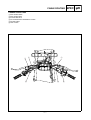
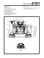
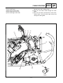
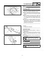
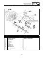
CABLE ROUTING
1
Rear brake switch
2
Rear brake cable
3
Front brake hose
4
On command four-wheel drive switch
5
Throttle cable
6
Horn switch
1
2
3
4
5
6
CABLE ROUTING

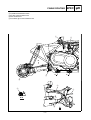
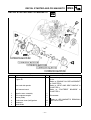
– 6 –
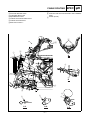
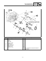
SPEC
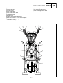
1
On command four-wheel drive switch lead
2
Front brake hose
3
Throttle cable
4
Rear brake cable
5
Rear brake switch lead
6
Handlebar switch
7
Starter cable
8
Coolant reservoir breather hose
9
Sub-wire harness 1 (to fan motor coupler)
0
Sub-wire harness 1 (to gear motor and four-
wheel drive switch)
A
Differential gear case breather hose
B
Fan motor breather hose
C
Front brake light switch lead
C
1
2
3
4
5
6
7
8
9
0
A
B
CABLE ROUTING

– 7 –
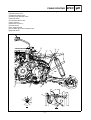
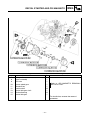
SPEC
1
Headlight coupler
2
Circuit breaker
3
Terminal
4
Terminal coupler
5
Engine temperature warning light
6
Four-wheel drive indicator light
7
Neutral indicator light
8
Reverse indicator light
9
Parking indicator light
0
Coolant reservoir breather hose
A
Differential gear case breather hose
B
Indicator light coupler
C
Main switch coupler
D
Ignition coil lead
È
Connect the headlight lead of the circuit breaker
to the headlight on the right side.
3
4
5
6
7
8
9
0
A
1
1
2
È
B
4
B
C
D
A
A
CABLE ROUTING

– 8 –
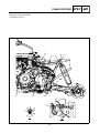
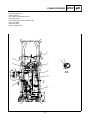
SPEC
1
Thermo switch
2
Fuel tank breather hose
3
Carburetor drain hose
4
Speedometer cable
5
Coolant reservoir breather hose
6
Coolant reservoir hose
7
Sub-wire harness 1
È
To hole on the front fender.
É
Insert the fuel tank into the hole in the handlebar
cover.
Ê
10 mm (0.4 in)
E
E
E
E
D
D
D
D
C
C
B
7
7
6
5
1
2
5
6
3
4
È
É
A
A
B
C-C
D-D
E-E
Ê
CABLE ROUTING

– 9 –
SPEC
1
Neutral switch lead
2
Starter motor lead
3
Negative battery lead
4
Water pump breather hose
5
Speed sensor
6
Carburetor drain hose
7
Wire harness
8
Sub-wire harness 2
9
Ground lead
0
AC magneto lead
A
Final drive gear case breather hose
B
Speed sensor
C
Rectifier/regulator
A
A
B
7
BA
0
9
8
A
C
6
5
4
3
2
1
È
É
Ê
A
B
CABLE ROUTING

– 10 –
SPEC
È
Fasten the AC magneto lead and starter motor lead with a plastic band.
É
To hole on the rear fender.
Ê
120 mm (4.72 in)
A
A
B
7
BA
0
9
8
A
C
6
5
4
3
2
1
È
É
Ê
A
B
CABLE ROUTING

– 11 –
SPEC
1
Spark plug lead
2
Rear brake cable
3
Select lever control cable
4
Rear brake reservoir hose
5
Rear brake light switch lead
È
Fasten the radiator inlet hose and fan motor
breather hose with a plastic band.
É
Pass the rear brake cable through the cable
guide.
Ê
Pass the rear brake reservoir hose, select lever
control cable, and rear brake light switch lead
through the cable guide.
A-A
A
A
1
2
3
4
5
4
É
Ê
È
CABLE ROUTING

– 12 –
SPEC
1
Fan motor breather hose
2
Cylinder head breather hose
3
Air filter case breather hose
4
Rear brake hose
5
Final drive gear case breather hose
A-A
3
5
4
4
3
1
2
B
B
A
A
A
A
4
CABLE ROUTING
La pagina si sta caricando...
La pagina si sta caricando...
La pagina si sta caricando...
La pagina si sta caricando...
La pagina si sta caricando...
La pagina si sta caricando...
La pagina si sta caricando...
La pagina si sta caricando...
La pagina si sta caricando...
La pagina si sta caricando...
La pagina si sta caricando...
La pagina si sta caricando...
La pagina si sta caricando...
La pagina si sta caricando...
La pagina si sta caricando...
La pagina si sta caricando...
La pagina si sta caricando...
La pagina si sta caricando...
La pagina si sta caricando...
La pagina si sta caricando...
La pagina si sta caricando...
-
 1
1
-
 2
2
-
 3
3
-
 4
4
-
 5
5
-
 6
6
-
 7
7
-
 8
8
-
 9
9
-
 10
10
-
 11
11
-
 12
12
-
 13
13
-
 14
14
-
 15
15
-
 16
16
-
 17
17
-
 18
18
-
 19
19
-
 20
20
-
 21
21
-
 22
22
-
 23
23
-
 24
24
-
 25
25
-
 26
26
-
 27
27
-
 28
28
-
 29
29
-
 30
30
-
 31
31
-
 32
32
-
 33
33
-
 34
34
-
 35
35
-
 36
36
-
 37
37
-
 38
38
-
 39
39
-
 40
40
-
 41
41


Yamaha 2002 YFM400FWA Manuale utente
- Categoria
- Motociclette
- Tipo
- Manuale utente
- Questo manuale è adatto anche per
in altre lingue
- English: Yamaha 2002 YFM400FWA User manual
Documenti correlati
-
Yamaha 5UME Manuale del proprietario
-
Yamaha FJR1300A Manuale utente
-
-
-
-
-
-