
C-BOX 400/410
Installation Manual


C-BOX 400/410
INSTALLATION MANUAL

DATALOGIC S.p.A.
Via Candini 2
40012 - Lippo di Calderara di Reno
Bologna - Italy
C-BOX 400/410
Ed.: 03/2006
ALL RIGHTS RESERVED
Datalogic S.p.A. reserves the right to make modifications and improvements without prior notification.
Datalogic shall not be liable for technical or editorial errors or omissions contained herein, nor for incidental or
consequential damages resulting from the use of this material.
Product names mentioned herein are for identification purposes only and may be trademarks and or
registered trademarks of their respective companies.
© Datalogic S.p.A. 2004 - 2006
821001010 (Rev 01)

CONTENTS
GUIDE TO INSTALLATION ........................................................................ iv
GENERAL VIEW .......................................................................................... v
SAFETY PRECAUTIONS............................................................................ ix
Power Supply................................................................................................ix
Safety Notes .................................................................................................ix
WEEE Compliance ....................................................................................... x
1 GENERAL FEATURES ................................................................................ 1
1.1 Description.................................................................................................... 1
1.1.1 DeviceNet ..................................................................................................... 2
2 INSTALLATION............................................................................................ 3
2.1 Package Contents......................................................................................... 3
2.2 Opening the Device ...................................................................................... 4
2.3 Mechanical Installation.................................................................................. 5
2.4 Electrical Connections and Setup ................................................................. 7
2.4.1 Power Supply................................................................................................ 8
2.4.2 System Wiring............................................................................................. 10
2.4.3 Scanner Chassis Grounding Jumper Settings ............................................ 12
2.4.4 OM4000 Jumper Settings ........................................................................... 12
2.5 DeviceNet Connections and Setup ............................................................. 13
2.5.1 DeviceNet Node Address (MAC ID) and Baud Rate Selection ................... 13
2.5.2 DeviceNet Connector (M12 Male External Sealed Micro Connector) ......... 13
2.5.3 Connection to a DeviceNet Network ........................................................... 14
2.5.4 C-BOX 4X0 Configuration for DeviceNet Slave Node................................. 15
2.6 Configuration Switch and 9-Pin Internal Connector ............................................ 16
2.7 Barcode Scanner Requirements................................................................. 18
2.8 Operating Modes ........................................................................................ 18
2.8.1 GET/TEST/SEND Functions....................................................................... 19
2.8.2 LED Indicators ............................................................................................ 21
2.9 Special Notes for Matrix Reader Setup....................................................... 23
2.9.1 Preparing C-Box 4x0 for Matrix Reader Communication ............................ 23
2.9.2 Matrix Reader Configuration Using VisiSet™ ............................................. 24
2.9.3 Completing C-Box 4x0 Configuration for Matrix-1000™ Readers............... 25
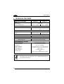
3 TECHNICAL FEATURES........................................................................... 26
iii

GUIDE TO INSTALLATION
The following can be used as a checklist to verify all of the steps necessary for
complete installation of the C-BOX 4X0.
1) Read all information in the section "Safety Precautions" at the beginning of this
manual.
2) Correctly position and mount the C-BOX 4X0 within the reach of the barcode
scanner cable, according to the information in paragraph 2.3.
3) Provide correct system cabling according to the signals necessary for your
application and DeviceNet settings (see all sub-paragraphs under 2.4).
The installation is now complete.
iv

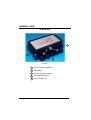
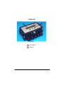
GENERAL VIEW
C-BOX 400
2
3
4
5
1
Figure A
25-pin scanner connector
Compression Connectors
Shield Nut
1
2
3
DeviceNet Connector
4
Cover screws (4)
5
v

C-BOX 410
2
1
Figure B
LCD display
Keypad
1
2
vi

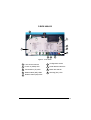
C-BOX 400/410
1
2
5
3
4
7
8
9
6
Figure C - Cover Inside
LCD contrast trimmer
1
2
Power on (PWR) LED
3
Transmission (TX) LED
4
Module status (MS) LEDs
5
Network status (NS) LEDs
6
7
8
Configuration switch
Node address selectors
Baud rate selector
9
Warning (WL) LED
vii

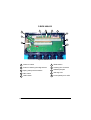
C-BOX 400/410
8
654
3
2
1
7
9
10
Figure E - Bottom Inside
Power on switch
1
2
Scanner chassis grounding selector
3
Spring clamp terminal blocks
5
4
GET button
TEST button
6
SEND button
7
8
9
A
uxiliary port connector
OM4000 jumpers
Warning LED
10
Power polarity error LED
viii

SAFETY PRECAUTIONS
POWER SUPPLY
ATTENTION: READ THIS INFORMATION BEFORE INSTALLING THE PRODUCT
- This product is intended to be installed by Qualified Personnel only.
The C-BOX 4X0 is intended to be supplied either by a UL Listed NEC Class 2 power
source, or a UL Listed ITE Limited Power Source (LPS), rated 10-30 V dc, minimum
0.5 A.
See par. 2.4.1 for correct power supply connections.
SAFETY NOTES
Observe the general rules for DeviceNet components when planning the C-BOX
installation.
Observe the guidelines in the DeviceNet specifications. DeviceNet is a trademark of
Open DeviceNet Vendor Association, Inc. (ODVA). Please refer to ODVA
(www.odva.org) for further details.
Please observe the following to avoid risk to personnel and damage to equipment
and to ensure that the C-BOX 4X0 functions correctly:
Safety Regulations Observe the guidelines in the VDE 0100 regulations for
handling electrical components,
Observe the applicable safety and accident prevention
regulations.
The C-BOX must only be installed or uninstalled by
qualified technical personnel with appropriate electro-
technical qualifications.
Bus Cable Bus wiring should only take place using DeviceNet cable.
The high data transfer rates can only be guaranteed with
the correct cable type.
Cable Lengths Refer to the manual for the DeviceNet master and to the
ODVA documentation for information on maximum cable
lengths for DeviceNet.
ix

Terminating Resistors Two 121 Ohm, 1% Metal Film, ¼ Watt terminating
resistors should be installed at each side of the DeviceNet
trunk line (not at the end of a drop line or in a node). If the
bus is incorrectly terminated, this can lead to errors in data
transfer or bus failure. Please refer to ODVA
documentation for further details.
Bus Connectors It is recommended to use only commercially available
DeviceNet connectors for connecting the bus.
When connecting up the C-BOX 4X0, it is recommended to observe the guidelines in
the VDE 0100 regulations for handling electrical equipment.
WEEE COMPLIANCE
x

GENERAL FEATURES
1
1 GENERAL FEATURES
1.1 DESCRIPTION
The C-BOX 4X0 is a connection box which converts RS232 communications to
DeviceNet. It is available in two models:
C-BOX 400, without display,
C-BOX 410, with a LCD display.
It operates as a DeviceNet “Group 2 Only Slave” using the predefined Master/Slave
connection set. The Polled, Bit Strobe and Change of State (COS) protocol types are
available.
It can be used as an accessory of the Datalogic scanners to perform the following
functions:
• Connect an RS232 scanner/reader to a DeviceNet network.
• Facilitate the connection of the scanner signals using a spring clamp connector.
• Get the scanner configuration and store it in memory. *
• Force the scanner to the Test operating mode. *
• Send the configuration stored in memory to the scanner. *
• In the C-BOX 410, visualize the data packet sent by the scanner on the LCD.
The C-BOX 400 / C-BOX 410 mechanical dimensions are 167 x 115 x 61 mm (6.57 x
4.53 x 2.40 in.). The C-BOX 400 weighs about 470 g (16.50 oz); the C-BOX 410
weighs about 530 g (18.70 oz).
Electrical connection is provided through spring clamp terminal blocks inside the
C-BOX 4X0.
The scanner is connected to the C-BOX 4X0 through a 25-pin connector placed on
the left side of the housing.
A 9-pin connector placed inside the C-BOX 4X0 facilitates connection between an
external PC and the auxiliary serial interface of the scanner.
The external M12 male connector is used to connect the C-BOX 4X0 to a DeviceNet
network.
* Function not compatible with Matrix-2000™ or Matrix-1000™.
1

C-BOX 400/410
1
A dedicated shield nut offers the possibility to further increase the C-BOX 4X0 noise
immunity by simply connecting the ground. The fixing screw type is 4-40 UNC, 1/8
inch.
1.1.1 DeviceNet
DeviceNet is a low level network that provides connections between simple industrial
devices (sensors, actuators) and higher level devices (controllers), and eliminates
expensive hardwiring.
It allows the transport of control oriented information associated with low level
devices and the transport of other information which is indirectly related to the system
being controlled, such as configuration parameters.
DeviceNet is a standard open network allowing the interchangeability of simple
devices while making interconnectivity of more complex devices.
The DeviceNet communication link is based on a broadcast oriented communication
protocol: the Controller Area Network (CAN) for Media Access Control and Physical
Signaling.
CAN defines the syntax or form of the data movement.
DeviceNet is a trademark of Open DeviceNet Vendor Association, Inc. (ODVA).
Please refer to ODVA (www.odva.org) for further details.
2

INSTALLATION
2
2 INSTALLATION
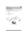
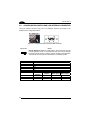
2.1 PACKAGE CONTENTS
Verify that the C-BOX 4X0 and all the parts supplied with the equipment are present
and intact when opening the packaging; the list of parts includes:
1) C-BOX 4X0
2) Installation manual
3) C-BOX 4X0 configuration CD-ROM
4) 2 mounting screws
3
1
2
4
Figure 1 - C-BOX 4X0 Package Contents
3

C-BOX 400/410
2
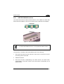
2.2 OPENING THE DEVICE
To install the C-BOX 4X0 or during normal maintenance, it is necessary to open it by
unscrewing the four cover screws:
CAUTION
The C-BOX 4X0 must be disconnected from the power supply
during this operation.
C-BOX 4X0
Figure 2 - Opening the C-BOX 4X0
It is possible to perform the following operations:
• Proceed with the cable connections (see paragraph 2.4.2).
• Set the DeviceNet Node Address (MAC ID) selection on the rotary switches.
• Set the DeviceNet Baud Rate on the specific rotary switch.
• Mount the C-BOX 4X0 to a wall or panel.
4

INSTALLATION
2
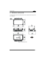
2.3 MECHANICAL INSTALLATION
The diagram below gives the overall dimensions of the C-BOX 4X0 and may be used
for its installation.
Figure 3 - Overall Dimensions
5

C-BOX 400/410
2
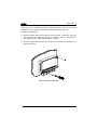
C-BOX 4X0 can be installed to operate in different positions. The two screw holes
inside the housing of the C-BOX 4X0 are for mechanical fixture (Figure 4).
To mount the C-BOX 4X0:
1) Open the C-BOX 4X0 by unscrewing the 4 cover screws. If necessary, using the
two mounting holes inside the device as a pattern, mark the panel with an
appropriate object and then drill two holes in the panel.
2) Align the C-BOX 4X0 and insert two screws and screw them into the panel until
tight (see Figure 4).
Figure 4 - Mounting C-BOX 4X0
6

INSTALLATION
2
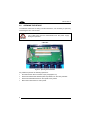
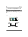
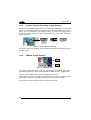
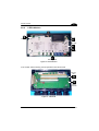
2.4 ELECTRICAL CONNECTIONS AND SETUP
The following figure shows the typical layout.
P
G
E
GR
D
NORE
DER
D
DeviceNet
MASTER
C-BOX 4X0
SCANNER
System
Cables
Figure 5 – System Layout
NOTE
Matrix readers are not compatible with the WinHost configuration
program. For Matrix reader setup first read par. 2.9 for details.
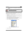
A PC can be connected to the C-BOX 4X0 (and consequently to the scanner
auxiliary interface) through the internal 9-pin connector. This allows monitoring of the
data transmitted by the scanner or configuration through the WinHost utility (see the
scanner Installation Manual for more details). The scanner auxiliary interface signals
are also available on the internal spring clamp connectors.
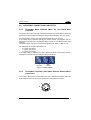
After making system cabling and switch settings (see sub-paragraphs under 2.4),
connect the scanner to the 25-pin connector on the left side of the C-BOX 4X0
housing.
Switch ON the C-BOX 4X0 power switch (see Figure 6).
By default, after power on, an automatic connection procedure takes place between
the C-BOX 4X0 and the scanner. During this phase, requiring a few seconds, the
warning LED is turned ON. Once the procedure had been completed successfully,
the warning LED is turned OFF.
7

C-BOX 400/410
2
NOTE
Autoconnection is not compatible with Matrix readers and must be
disabled in the C-BOX 4x0 configuration. See par. 2.9 for details.
To disable this automatic connection procedure, refer to WinHost Help Online.
After system functioning has been verified, close the C-BOX 4X0 using the 4 cover
screws making sure the rubber seal is fitted correctly between the parts of the
housing.
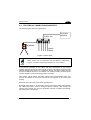
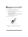
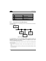
2.4.1 Power Supply
Power is supplied to the C-BOX 4X0 through the pins provided on the spring clamp
connector.
The power switch (see Figure 6) switches the power supply ON or OFF for both the
C-BOX 4X0 and the connected scanner.
ON
OFF
S1
Figure 6 - Power Switch ON/OFF Positions
C-BOX
1
2
VS
GND
USER INTERFACE
GND
V+ (10 - 30 Vdc)
Figure 7 - Power Supply Connections
The power supply must be between 10 and 30 Vdc only.
8
La pagina si sta caricando...
La pagina si sta caricando...
La pagina si sta caricando...
La pagina si sta caricando...
La pagina si sta caricando...
La pagina si sta caricando...
La pagina si sta caricando...
La pagina si sta caricando...
La pagina si sta caricando...
La pagina si sta caricando...
La pagina si sta caricando...
La pagina si sta caricando...
La pagina si sta caricando...
La pagina si sta caricando...
La pagina si sta caricando...
La pagina si sta caricando...
La pagina si sta caricando...
La pagina si sta caricando...
La pagina si sta caricando...
-
 1
1
-
 2
2
-
 3
3
-
 4
4
-
 5
5
-
 6
6
-
 7
7
-
 8
8
-
 9
9
-
 10
10
-
 11
11
-
 12
12
-
 13
13
-
 14
14
-
 15
15
-
 16
16
-
 17
17
-
 18
18
-
 19
19
-
 20
20
-
 21
21
-
 22
22
-
 23
23
-
 24
24
-
 25
25
-
 26
26
-
 27
27
-
 28
28
-
 29
29
-
 30
30
-
 31
31
-
 32
32
-
 33
33
-
 34
34
-
 35
35
-
 36
36
-
 37
37
-
 38
38
-
 39
39


Datalogic C-BOX 400 Guida d'installazione
- Tipo
- Guida d'installazione
- Questo manuale è adatto anche per
in altre lingue
Documenti correlati
-
Datalogic C-BOX 200 Guida d'installazione
-
-
-
-
Datalogic DS2400N Guida di riferimento
-
-
Datalogic Switch SC6000 Manuale utente
-
-
Datalogic DS6300 Guida di riferimento
-