AVENTICS Compact ejector, series ECD-SV Istruzioni per l'uso
- Tipo
- Istruzioni per l'uso

R412025989/2019-03, Replaces: 2019-03, DE/EN/FR/IT/ES/SV
Kompaktejektor
Compact ejector
Ejecteur compact
Eiettore compatto
Eyector compacto
Kompaktejektor
ECD-SV
Betriebsanleitung | Operating instructions | Notice d’instruction |
Istruzioni per l’uso | Instrucciones de servicio | Bruksanvisning

Deutsch
1 Zu dieser Dokumentation
Diese Anleitung enthält wichtige Informationen, um das Produkt sicher und
sachgerecht zu montieren und in Betrieb zu nehmen.
O Lesen Sie diese Anleitung vollständig und insbesondere das Kapitel 2
„Sicherheitshinweise“, bevor Sie mit dem Produkt arbeiten.
Gültigkeit der Dokumentation
O Diese Dokumentation gilt für Kompaktejektoren der Serie ECD-SV.
Prüfen Sie anhand des Typenschilds auf dem Produkt und der Beschreibung in
Kapitel 4, welche Variante Sie vorliegen haben und ob sie mit Ihrer Bestellung
übereinstimmt.
Zusätzliche Dokumentationen
O Beachten Sie auch die Anleitungen der übrigen Anlagenkomponenten.
O Beachten Sie außerdem allgemein gültige, gesetzliche und sonstige verbindliche
Regelungen der europäischen bzw. nationalen Gesetzgebung sowie die in Ihrem
Land gültigen Vorschriften zur Unfallverhütung und zum Umweltschutz.
Darstellung von Informationen
Warnhinweise
In dieser Anleitung stehen Warnhinweise vor einer Handlungsanweisung, bei der die
Gefahr von Personen- oder Sachschäden besteht. Die beschriebenen Maßnahmen
zur Gefahrenabwehr müssen eingehalten werden.
Aufbau von Warnhinweisen
Bedeutung der Signalwörter
Symbole
2 Sicherheitshinweise
Das Produkt wurde gemäß den allgemein anerkannten Regeln der Technik
hergestellt. Trotzdem besteht die Gefahr von Personen- und Sachschäden, wenn Sie
die folgenden grundsätzlichen Sicherheitshinweise und die Warnhinweise vor
Handlungsanweisungen in dieser Anleitung nicht beachten.
O Lesen Sie diese Anleitung gründlich und vollständig, bevor Sie mit dem Produkt
arbeiten.
O
Bewahren Sie die Anleitung so auf, dass sie jederzeit für alle Benutzer zugänglich ist.
O Geben Sie das Produkt an Dritte stets zusammen mit der Betriebsanleitung
weiter.
Bestimmungsgemäße Verwendung
Der Ejektor ist ausschließlich dazu bestimmt, in eine Maschine bzw. Anlage
eingebaut oder mit anderen Komponenten zu einer Maschine bzw. Anlage
zusammengefügt zu werden.
O Halten Sie die in den technischen Daten genannten Betriebsbedingungen und
Leistungsgrenzen ein. Verwenden Sie als Medium ausschließlich neutrale Gase
gemäß EN 983.
O Verwenden Sie den Ejektor ausschließlich zur Vakuumerzeugung in
Pneumatikanlagen.
SIGNALWORT
Art und Quelle der Gefahr
Folgen bei Nichtbeachtung der Gefahr
O Maßnahmen zur Abwehr der Gefahr
GEFAHR
Kennzeichnet eine gefährliche Situation, in der Tod oder schwere
Körperverletzung eintreten werden, wenn sie nicht vermieden wird.
WARNUNG
Kennzeichnet eine gefährliche Situation, in der Tod oder schwere
Körperverletzung eintreten können, wenn sie nicht vermieden wird.
VORSICHT
Kennzeichnet eine gefährliche Situation, in der leichte bis mittelschwere
Körperverletzungen eintreten können, wenn sie nicht vermieden wird.
ACHTUNG
Kennzeichnet Sachschäden: Das Produkt oder die Umgebung können beschädigt
werden.
Wenn diese Information nicht beachtet wird, kann das zu
Verschlechterungen im Betriebsablauf führen.
Kompaktejektoren sind für den professionellen Gebrauch und nicht für die private
Verwendung bestimmt. Sie dürfen Kompaktejektoren nur im industriellen Bereich
einsetzen (Klasse A nach DIN EN 55011). Für den Einsatz im Wohnbereich (Wohn-,
Geschäfts- und Gewerbebereich) ist eine Einzelgenehmigung bei einer Behörde oder
Prüfstelle einzuholen.
Die bestimmungsgemäße Verwendung schließt auch ein, dass Sie diese Anleitung
und insbesondere das Kapitel 2 „Sicherheitshinweise“ vollständig gelesen und
verstanden haben.
Nicht bestimmungsgemäße Verwendung
O Verwenden Sie den Ejektor nicht in explosionsgefährdeten Bereichen.
O Saugen Sie mit dem Ejektor keine Flüssigkeiten, aggressive oder brennbare Gase
und Schüttgüter (z. B. Granulate) an.
Qualifikation des Personals
Die Montage, Inbetriebnahme, Demontage und Instandhaltung (inkl. Wartung und
Pflege) erfordern grundlegende mechanische und pneumatische Kenntnisse sowie
Kenntnisse der zugehörigen Fachbegriffe.
Um die Betriebssicherheit zu gewährleisten, dürfen diese Tätigkeiten daher nur von
einer entsprechenden Fachkraft oder einer unterwiesenen Person unter Leitung
einer Fachkraft durchgeführt werden.
Eine Fachkraft ist, wer aufgrund seiner fachlichen Ausbildung, seiner Kenntnisse
und Erfahrungen sowie seiner Kenntnisse der einschlägigen Bestimmungen die ihm
übertragenen Arbeiten beurteilen, mögliche Gefahren erkennen und geeignete
Sicherheitsmaßnahmen treffen kann. Die Fachkraft muss die einschlägigen
fachspezifischen Regeln einhalten.
Allgemeine Sicherheitshinweise
W Beachten Sie die gültigen Vorschriften zur Unfallverhütung und zum
Umweltschutz im Verwenderland und am Arbeitsplatz.
W Verwenden Sie AVENTICS-Produkte nur in technisch einwandfreiem Zustand.
W Prüfen Sie das Produkt auf offensichtliche Mängel, wie beispielsweise Risse im
Gehäuse oder fehlende Schrauben, Abdeckkappen, Dichtungen.
W Sie dürfen das Produkt grundsätzlich nicht verändern oder umbauen.
W Das Öffnen des Produkts führt zur Beschädigung des „tested“-Aufklebers.
Dadurch erlischt die Gewährleistung
W Die Gewährleistung erlischt bei fehlerhafter Montage.
W Belasten Sie das Produkt unter keinen Umständen in unzulässiger Weise
mechanisch.
W Schützen Sie das Produkt generell vor Beschädigungen.
W Warnungen und Angaben zum Produkt dürfen nicht mit Farbe etc. überdeckt
werden, sondern müssen stets gut lesbar sein.
W Für Schäden, die durch die Verwendung von anderen als Originalersatzteilen
oder Originalzubehör entstehen, ist jegliche Haftung unsererseits
ausgeschlossen. Ausgenommen von der Gewährleistung sind alle
Verschleißteile.
Produkt- und technologieabhängige Sicherheitshinweise
Bei der Montage
W Schalten Sie immer den relevanten Anlagenteil drucklos und spannungsfrei,
bevor Sie das Produkt montieren bzw. Stecker anschließen oder ziehen. Sichern
Sie die Anlage gegen Wiedereinschalten.
W Verlegen Sie die Kabel und Leitungen so, dass diese nicht beschädigt werden und
niemand darüber stolpern kann.
W Beachten Sie die Anschlusssymbole und Anschlussbezeichnungen auf dem
Ejektor.
W Verwenden Sie ausschließlich die vorgesehenen Anschlussmöglichkeiten,
Befestigungsbohrungen und Befestigungsmittel.
W Stellen Sie vor der Inbetriebnahme sicher, dass alle Dichtungen und Verschlüsse
der Steckverbindungen korrekt eingebaut und unbeschädigt sind, um zu
verhindern, dass Flüssigkeiten und Fremdkörper in das Produkt eindringen
können.
W Verwenden Sie für die Komponenten ausschließlich die folgende
Spannungsversorgung:
– 24-V-DC PELV-Stromkreise nach DIN EN 60204-1/IEC 60204-1.
– Die Stromquelle für PELV muss ein Sicherheitstrenntransformator nach
IEC 61558-1 oder IEC 61558-2-6 sein oder eine Stromquelle, die den gleichen
Sicherheitsgrad erfüllt wie ein Sicherheitstrenntransformator.
– Stellen Sie sicher, dass die Spannungsversorgung des Netzteils immer
kleiner als 300 V AC (Außenleiter – Neutralleiter) ist.
WARNUNG
Offene Vakuum-/Abluftanschlüsse und Sauggreifer
Verletzungsgefahr durch An- oder Einsaugen von Augen oder anderen
Körperteilen. Verletzungsgefahr, da Abluft und eventuell angesaugte Medien und
Teile mit hoher Geschwindigkeit aus dem Abluftanschluss austreten.
O Blicken Sie niemals in saugende oder nicht saugende Vakuumöffnungen (z. B.
Vakuumanschlüsse oder angeschlossene Sauggreifer).
O Blicken oder treten Sie niemals in den Abluftstrahl.
AVENTICS | ECD-SV | R412025989–BAL–001–AC | Deutsch 1

W Verwenden Sie bei stark verschmutzter Vakuum-/Umgebungsluft einen
Vakuum-Tassenfilter VFC zwischen dem Vakuumanschluss und zu
evakuierenden Volumina.
Bei der Inbetriebnahme
W Stellen Sie sicher, dass alle elektrischen und pneumatischen Anschlüsse belegt
oder verschlossen sind. Nehmen Sie nur ein vollständig installiertes Produkt in
Betrieb.
W Beim Einschalten der Versorgungsspannung können sich Ausgangssignale
(diskrete Signale sowie IO-Link-Signale) verändern. Abhängig von der
Funktionalität der Maschine/Anlage kann dies zu schweren Personen- oder
Sachschäden führen.
Während des Betriebs
W Verwenden Sie den Ejektor nicht in spritzwassergefährdeten Bereichen.
W Durch Druckluft können geschlossene Gefäße explodieren. Durch Vakuum
können geschlossene Gefäße implodieren.
W Der Ejektor darf nur mit Schalldämpfer betrieben werden. Blicken Sie niemals in
den Abluftstrahl des Schalldämpfers.
W Der Ejektor emittiert Schall. Wir empfehlen das Tragen eines Gehörschutzes.
W Werden entgegen der bestimmungsgemäßen Verwendung gefährlicher Staub,
Ölnebel, Dämpfe, Aerosole oder Ähnliches abgesaugt, gelangen diese in die
Abluft. Dies kann zu Vergiftungen führen.
W Der Betrieb außerhalb der spezifizierten Leistungsgrenzen ist nicht zulässig.
Fehlfunktion sowie Zerstörung können die Folge sein.
W Es dürfen sich keine Personen im Transportbereich der angesaugten Nutzlast
aufhalten.
W Im Automatikbetrieb der Maschine/Anlage dürfen sich keine Personen im
Gefahrenbereich befinden.
W Das Fachpersonal muss auch mit dem Steuerungskonzept der Anlage vertraut
sein. Hier sind besonders redundant ausgeführte Steuerungsteile und
Rückmeldungssignale der Anlage zu beachten.
Bei der Reinigung
W Verwenden Sie niemals Lösungsmittel oder aggressive Reinigungsmittel.
Reinigen Sie das Produkt ausschließlich mit einem feuchten Tuch. Verwenden
Sie dazu ausschließlich Wasser und ggf. ein mildes Reinigungsmittel.
W Verwenden Sie zur Reinigung keine Hochdruckreiniger.
Bei der Instandhaltung und Instandsetzung
W Stellen Sie sicher, dass keine Leitungsverbindungen, Anschlüsse und Bauteile
gelöst werden, solange die Anlage unter Druck und Spannung steht. Sichern Sie
die Anlage gegen Wiedereinschalten.
3Lieferumfang
Im Lieferumfang sind enthalten:
W 1 Kompaktejektor ECD-SV
W Betriebsanleitung
4 Zu diesem Produkt
Produktübersicht
In Abb. ist der Kompaktejektor ECD-SV dargestellt.
Funktionsbeschreibung
Vakuumerzeugung (Ansaugen des Werkstücks)
Der Ejektor ist zum Teilehandling mittels Vakuum in Verbindung mit Saugsystemen
konzipiert.
Angesteuert wird der Ejektor mittels elektrischer Signale über den M12-Stecker.
Über den Signaleingang „Saugen“ wird die Venturidüse aktiviert bzw. deaktiviert. Bei
der NO-Variante wird die Venturidüse bei anstehendem Signaleingang „Saugen“
deaktiviert, bei der NC-Variante hingegen aktiviert.
Ein integrierter Sensor erfasst das von der Venturidüse erzeugte Vakuum. Dieses
wird über eine Elektronik ausgewertet und dient als Grundlage zur Anzeige von
Systemzuständen und zum Schalten des Ausgangs.
Der Ejektor hat eine integrierte Luftsparfunktion. Der Ejektor regelt im
Betriebszustand „Saugen“ automatisch das Vakuum. Die Elektronik schaltet dabei
die Venturidüse bei Erreichen des vom Benutzer eingestellten Schaltpunkts H1 ab.
Die integrierte Rückschlagklappe verhindert bei angesaugten Objekten mit dichter
Oberfläche ein Abfallen des Vakuums. Fällt das Systemvakuum durch auftretende
Leckagen unter den Schaltpunkt H1-h1, wird die Venturidüse wieder eingeschaltet.
Bei kleinen zu evakuierenden Volumina kann es vorkommen, dass das
Vakuum erst wesentlich über dem eingestellten Schaltpunkt H1
abgeschaltet wird. Dieses Verhalten stellt keinen Fehler dar.
1
1
Abblasen (Ablegen des Werkstücks)
Im Betriebszustand „Abblasen“ wird der Vakuumkreis des Ejektors mit Druckluft
beaufschlagt. Hiermit wird ein schneller Vakuumabbau und somit ein schnelles
Ablegen des Werkstücks gewährleistet. Der Betriebszustand „Abblasen“ kann
entweder extern oder intern angesteuert werden.
Bei extern gesteuertem Abblasen wird der Betriebszustand „Abblasen“ durch den
Signaleingang „Abblasen“ aktiviert.
Beim intern gesteuerten Auto-Abblasen wird automatisch nach Verlassen des
Betriebszustands „Saugen“ für eine bestimmte Zeit das Ventil „Abblasen“
angesteuert.
Produktbeschreibung
Varianten
J
eder Ejektor hat eine genaue Artikelbezeichnung (z. B. ECD-SV-EC-07-NO)
.
Die Aufschlüsselung der Artikelbezeichnung ergibt sich wie folgt:
O Entnehmen Sie weitere Details zu Ihrer Variante dem Typenschild.
5 Anzeige- und Bedienelemente
Der Ejektor verfügt über eine Folientastatur mit LED-Balken sowie vier zusätzliche
Leuchtdioden.
Vakuumanzeige/Druckanzeige
Über die 8-stufige LED-Balkenanzeige wird stets das aktuelle Systemvakuum
angezeigt. Mittels der 2 Leuchtdioden H1 und H2 wird angezeigt, in welchem Bereich
das Vakuumniveau in Bezug zu den eingestellten Schwellwerten liegt.
LEDs Prozesszustand
Dem Prozesszustand „Saugen“ und dem Prozesszustand „Abblasen“ ist jeweils eine
LED zugeordnet.
Der Ejektor verfügt zusätzlich über die Betriebsart „Manueller Betrieb“.
In dieser Betriebsart kann über die Tasten der Folientastatur der Ejektor
angesteuert werden. Siehe auch Abschnitt „Manueller Betrieb“.
Typ ECD-SV
Funktionsweise:
elektrisch
EC
Leistungsklasse 07; 10; 15
Ruhestellung NO (normally open)
stromlos saugend
NC (normally closed)
stromlos nicht saugend
Position Beschreibung
1 LED-Balken
2LEDs Schwellwerte H1 und H2
3Menü-Taste
4Up-Taste
5Down-Taste
6 LED Prozesszustand „Saugen“
7 LED Prozesszustand „Abblasen“
Status LEDs Status Ejektor
LEDs sind beide aus Ejektor saugt nicht
LED Prozesszustand
„Saugen“ leuchtet
konstant
Ejektor saugt, bzw. ist in
Regelung
LED Prozesszustand
„Abblasen“ leuchtet
konstant
Ejektor bläst ab
3
715
4
236
AVENTICS | ECD-SV | R412025989–BAL–001–AC | Deutsch 2

LEDs Schwellwerte H1 und H2
Die LEDs der Schwellwerte H1 und H2 zeigen die Höhe des aktuellen
Systemvakuums in Bezug auf die eingestellten Schaltpunkte an.
Zusätzliche Anzeigefunktionen
6Montage
Der Ejektor darf erst in Betrieb genommen werden, wenn er in die Maschine/die
Anlage, für die er bestimmt ist, eingebaut ist.
Beim Betrieb des Ejektors werden alle Ein- und Ausgangssignale direkt oder über
intelligente Anschlussboxen mit einer Steuerung verbunden.
Hierfür sind, neben der Versorgungsspannung, zwei Eingangs- und ein
Ausgangssignal anzuschließen, über welche der Ejektor mit der Steuerung
kommuniziert.
Hiermit können die Grundfunktionen des Ejektors wie „Saugen“ und „Abblasen“
sowie die Rückmeldungen genutzt werden. Im Einzelnen sind dies:
Sämtliche Einstellungen der Parameter erfolgen über die Bedien- und
Anzeigeelemente.
Ejektor montieren
Der Ejektor kann wahlweise mit Schrauben oder mittels Hutschienenklemme
montiert werden, siehe Abbildung
und . Abmessungen siehe Abbildung .
Status LEDs Status Ejektor
LEDs sind beide aus Vakuum ansteigend:
Vakuum < H2
Vakuum fallend:
Vakuum < (H2-h2)
LED H2 leuchtet konstant Vakuum ansteigend:
Vakuum > H2 und < H1
Vakuum fallend:
Vakuum > (H2-h2) und < (H1-h1)
LEDs leuchten beide
konstant
Vakuum ansteigend:
Vakuum > H1
Vakuum fallend:
Vakuum > (H1-h1)
Status LED-Balken Bedeutung
Max.-LED blinkt kurz auf,
sonst keine LED aktiv
Versorgungsspannung vorhanden
10%-LED blinkt schnell Vakuum < zulässiger Bereich
(z. B. während des Abblasens)
Gesamter LED-Balken
leuchtet,
Max.-LED blinkt schnell
Vakuum > zulässiger Bereich
Max.-LED blinkt schnell Versorgungsspannung >
zulässiger Bereich
Eingänge des Ejektors Ausgang des Ejektors
W Saugen EIN/AUS
W Abblasen EIN/AUS
W Rückmeldung H2
Bei der Montage der Befestigungsschrauben wird die Verwendung von
Unterlegscheiben empfohlen.
H1
H2
H1
H2
H1
H2
2
4
1
4
1
2
Ejektor pneumatisch anschließen
W Es darf nur ausreichend gewartete Druckluft eingesetzt werden (Luft oder
neutrales Gas gemäß EN 983, gefiltert 5 μm, geölt oder ungeölt).
W Schmutzpartikel oder Fremdkörper in den Anschlüssen des Ejektors oder in den
Schlauch- oder Rohrleitungen können die Funktion des Ejektors stören oder zum
Funktionsverlust führen.
W Verlegen Sie Schlauch- und Rohrleitungen möglichst kurz.
W Durch zu klein gewählte Innendurchmesser auf der Druckluftseite wird nicht
genügend Druckluft zugeführt. Der Ejektor erreicht seine Leistungsdaten
dadurch nicht.
W Ein zu klein gewählter Innendurchmesser auf der Vakuumseite bewirkt einen zu
hohen Strömungswiderstand. Dadurch sinkt die Saugleistung und die
Ansaugzeiten erhöhen sich. Außerdem verlängern sich die Abblaszeiten.
W Verwenden Sie für den Ejektor nur die empfohlenen Schlauch- oder
Rohrinnendurchmesser. Wenn dies nicht möglich ist, verwenden Sie den
nächstgrößeren Durchmesser.
Empfohlene Innendurchmesser
So schließen Sie den Ejektor pneumatisch an, siehe Abbildung :
1. Schalten Sie den relevanten Anlagenteil drucklos.
2. Verlegen Sie die Schläuche knick- und quetschfrei.
3. Verbinden Sie den Druckluftschlauch mit dem Druckluftanschluss (8) und den
Vakuumschlauch mit dem Vakuumanschluss (4).
Ejektor elektrisch anschließen
W Der elektrische Anschluss erfolgt über einen 5-poligen M12-Stecker, der den
Ejektor mit Spannung versorgt sowie die beiden Eingangssignale und das
Ausgangssignal beinhaltet. Ein- und Ausgänge sind nicht galvanisch voneinander
getrennt.
W Verwenden Sie ausschließlich Schutzkleinspannung (PELV) und sorgen Sie für
eine sichere elektrische Trennung der Betriebsspannung gemäß EN 60204.
W Die maximale Leitungslänge für die Versorgungsspannung und die
Signaleingänge und Signalausgänge beträgt 30 m.
Pinbelegung des Anschlusssteckers
M12-Stecker 5-polig
VORSICHT
Anlage steht im Betrieb unter Druck
Das Arbeiten an der Anlage unter Druck kann zu Verletzungen und
Beschädigungen führen.
O Entlüften Sie vor dem Arbeiten an der Anlage alle relevanten Anlagenteile.
ECD-SV-EC-...
Leistungsklasse
Innendurchmesser [mm]
1)
1) Bezogen auf eine maximale Schlauchlänge von 2 m. Bei größeren Schlauchlängen wählen
Sie die Querschnitte entsprechend größer.
Druckluftseitig Vakuumseitig
07 4 4
10 4 4
15 4 6
VORSICHT
Anlage steht im Betrieb unter elektrischer Spannung
Das Arbeiten an der Anlage unter Spannung kann zu Verletzungen durch
Stromschlag oder zu Beschädigungen der Komponenten führen.
O Schalten Sie vor dem Arbeiten an der Anlage alle relevanten Anlagenteile
spannungsfrei.
O Verbinden und trennen Sie Steckverbindungen nur, wenn alle relevanten
Anlageteile spannungsfrei sind.
Stecker Pin Symbol Funktion
1U
S/A
Versorgungsspannung
2 IN1 Signaleingang „Saugen“
3Gnd
S/A
Masse
4 OUT Signalausgang „Teilekontrolle“ (H2-h2)
5 IN2 Signaleingang „Abblasen“
5
1
5
34
21
AVENTICS | ECD-SV | R412025989–BAL–001–AC | Deutsch 3

So schließen Sie den Ejektor elektrisch an, siehe Abbildung :
1. Schalten Sie den relevanten Anlagenteil spannungsfrei.
2. Verlegen Sie die Kabel knick- und quetschfrei.
3. Verbinden Sie die Spannungsversorgung mit dem elektrischen Anschluss des
Ejektors (5).
Projektieren
Zum Betrieb des Ejektors müssen alle Prozesssignale parallel verdrahtet werden. Je
Ejektor sind somit drei Leitungen für die Prozesssignale nötig.
Prozessdaten INPUT (SPS)
Prozessdaten OUTPUT (SPS)
7 Inbetriebnahme und Betrieb
Direktanschluss Anschluss über I/O-Box
externes Abblasen automatisches Abblasen
Zum direkten Anschluss
des Ejektors an die
Steuerung können z. B.
AVENTICS-Anschluss-
leitungen verwendet
werden.
W Verbindungskabel,
Serie CON-RD, 5 m,
Materialnummer:
R412026780*
Zum Anschluss des Ejektors an I/O-Boxen können
z. B. AVENTICS-Anschlussleitungen und AVENTICS-
Anschlussverteiler verwendet werden.
W Verbindungskabel, Serie CON-RD, 5 m,
Materialnummer: 8946054702*
W Y-Verbindung, Serie CON-RD,
Materialnummer: R412026785*
* Siehe Kapitel 10 „Zubehör“
Signal Symbol Parameter
0 OUT 1 Schaltpunkt H2 (Teilekontrolle)
Signal Symbol Parameter
0 IN 1 Saugen EIN/AUS
1 IN 2 Abblasen EIN/AUS
VORSICHT
Personenschäden oder Sachschäden durch Nichteinhaltung der
fachspezifischen Regeln
Der Betrieb des Ejektorsystems ohne Netzgeräte und ohne Einhaltung der Norm
EN 60204 kann zu Personenschäden und zur Beschädigung des Systems und der
daran angeschlossenen Komponenten führen.
O Betreiben Sie das System ausschließlich über Netzgeräte mit
Schutzkleinspannung (PELV) und sicherer elektrischer Trennung der
Versorgungsspannung gemäß EN 60204.
O Steckverbinder nicht unter Spannung verbinden oder trennen.
WARNUNG
Schwere Personen- oder Sachschäden durch bewegte Maschinen-/
Anlagenteile
Beim Einschalten der Versorgungsspannung kann sich der Signalausgang
verändern. Abhängig von der Funktionalität der Maschine kann sich die
Maschine/Anlage in Bewegung setzen.
O Achten Sie darauf, dass sich beim Einschalten der Maschine/Anlage keine
Personen im Transportbereich befinden.
1
BUS
U
S
/U
A
BUS
I/O
U
S
/U
A
BUS
I/O
U
S
/U
A
Betriebszustände
Die Ejektoren werden nach ihrer Grundstellung im spannungslosen Zustand
unterschieden zwischen NO (normally open) und NC (normally closed).
Automatik
Wird der Ejektor an die Versorgungsspannung angeschlossen, ist der Ejektor
betriebsbereit und befindet sich im Automatikbetrieb. Dies ist der normale
Betriebszustand, in dem der Ejektor über die Anlagensteuerung betrieben wird.
Manuell
Neben dem Automatikbetrieb kann durch die Bedienung über die Tasten der
Folientastatur der Ejektor seinen Betriebszustand ändern und in den manuellen
Betrieb wechseln.
Parametrierung
Die Parametrierung des Ejektors erfolgt immer aus dem Automatikbetrieb heraus.
Generelle Funktionen
Manueller Betrieb
Im manuellen Betrieb können die Ejektorfunktionen „Saugen“ und „Abblasen“ mit
den Tasten des Bedienfeldes gesteuert werden.
In dieser Betriebsart blinken die beiden LED „H1“ und „H2“.
Aktivieren „Manueller Betrieb“
O Um die Betriebsart „Manueller Betrieb“ zu aktivieren,
halten Sie die Taste und Taste > 3 s lang gleichzeitig gedrückt.
Manuelles Saugen
O Um in der Betriebsart „Manueller Betrieb“ den Betriebszustand „Saugen“ zu
aktivieren, drücken Sie die Taste .
O Um den Betriebszustand „Saugen“ wieder zu verlassen, drücken Sie erneut die
Taste oder die Taste .
Manuelles Abblasen
O Um in der Betriebsart „Manueller Betrieb“ den Betriebszustand „Abblasen“ zu
aktivieren, drücken Sie die Taste und halten Sie sie gedrückt.
O Um den Betriebszustand „Abblasen“ zu beenden, lassen Sie die Taste los.
WARNUNG
Offene Vakuum-/Abluftanschlüsse und Sauggreifer
Verletzungsgefahr durch An- oder Einsaugen von Augen oder anderen
Körperteilen. Verletzungsgefahr, da Abluft und eventuell angesaugte Medien und
Teile mit hoher Geschwindigkeit aus dem Abluftanschluss austreten.
O Blicken Sie niemals in saugende oder nicht saugende Vakuumöffnungen
(z. B. Vakuumanschlüsse oder angeschlossene Sauggreifer).
O Blicken oder treten Sie niemals in den Abluftstrahl.
WARNUNG
Personenschäden oder Sachschäden durch bewegte Maschinen-/Anlagenteile
Beim Einrichten im manuellen Betrieb können sich Ausgangssignale verändern
und externen Signale (über den M12-Stecker von der SPS kommend) können den
manuellen Betrieb beenden wodurch die Maschine/Anlage sich in Bewegung
setzen kann.
O Achten Sie darauf, dass sich beim Einrichten des manuellen Betriebs die
Maschine/Anlage nicht in Bewegung setzt und sich keine Personen im
Transportbereich befinden.
O Stellen Sie sicher, dass während des manuellen Betriebs keine Steuerbefehle
von der SPS kommen und den Ejektor in Automatikbetrieb versetzen.
Herunterfallende Nutzlast durch fehlendes Vakuum
Das Starten des manuellen Betriebs führt immer zum Betriebszustand
„pneumatisch AUS“, d. h. aktives Saugen wird durch den manuellen Betrieb
unterbrochen. Nutzlasten können dadurch herunterfallen.
O Stellen Sie sicher, dass sich unter der Nutzlast im Transportbereich keine
Personen befinden.
Bei eingeschalteter Luftsparfunktion ist diese auch in der Betriebsart
„Manueller Betrieb“ aktiv.
6
7
AVENTICS | ECD-SV | R412025989–BAL–001–AC | Deutsch 4

Deaktivieren „Manueller Betrieb“
O Um die Betriebsart „Manueller Betrieb“ zu verlassen, drücken Sie die Taste .
Außerdem wird die Betriebsart „Manueller Betrieb“ auch durch die
Zustandsänderung der externen Signaleingänge verlassen.
Überwachung des Systemvakuums
Jeder Ejektor verfügt über einen integrierten Sensor zur Überwachung des aktuellen
Systemvakuums. Die Höhe des Vakuums gibt Aufschluss über den Prozess und
beeinflusst folgende Signale und Parameter:
W Schwellwert-LED H1
W Schwellwert-LED H2
W Signalausgang H2
Regelungsfunktion
Der Ejektor bietet mit dieser Funktion die Möglichkeit, Druckluft zu sparen. Bei
Erreichen der eingestellten Schaltschwelle H1 wird die Vakuumerzeugung
unterbrochen. Fällt das Vakuum durch Leckage unterhalb die Hystereseschwelle
H1-h1, beginnt die Vakuumerzeugung erneut.
Die Regelungsfunktion kann deaktiviert werden, indem der Schwellwert für H1 auf
„Max.“ eingestellt wird.
Abblasmodi
Extern gesteuertes Abblasen
Das Ventil „Abblasen“ wird über den Signaleingang „Abblasen“ direkt angesteuert.
Der Ejektor bläst für die Dauer des anstehenden Signals ab.
Intern zeitgesteuertes Abblasen
Das Ventil „Abblasen“ wird bei Verlassen des Betriebszustands „Saugen“
automatisch für die eingestellte Zeit angesteuert. Durch diese Funktion kann ein
Ausgang an der Steuerung eingespart werden.
Signalausgang
Der Ejektor verfügt über einen Signalausgang.
Ausgangsfunktion
Der Signalausgang ist ein Schließerkontakt und kann nicht umgestellt werden.
Der Signalausgang wird bei Über- bzw. Unterschreiten des Systemvakuums des
zugehörigen Schwellwertes ein- bzw. ausgeschaltet.
Vakuumeinheit
Die Einheit des über den LED-Balken angezeigten Vakuumniveaus wird in Prozent
vom maximal erreichbaren Vakuum angezeigt.
Liegt das Vakuum außerhalb des zulässigen Bereichs blinkt die angrenzende LED
mit hoher Frequenz. D. h. beim Anlegen von Überdrücken blinkt die 10%-LED.
Versorgungsspannungsanzeige
In Betriebszuständen, in denen keine LED aktiv ist, blitzt die Max.-LED immer wieder
kurz auf. Sie zeigt dadurch eine Versorgungsspannung an.
Tastensperre
O Um die Tasten zu verriegeln, drücken Sie die Taste und die Taste
gleichzeitig.
O Um die Tastensperre wieder aufzuheben, drücken Sie die beiden Tasten erneut.
WARNUNG
Verletzungsgefahr durch bewegte Objekte
Das automatische Verlassen des manuellen Betriebs durch die Änderung
externer Signale kann ein Handhabungsobjekt durch Ansaugen oder Abblasen in
Bewegung setzen.
O Achten Sie darauf, dass beim Verlassen des manuellen Betriebs keine Objekte
bewegt werden und sich keine Personen im Transportbereich befinden.
Das zeitgesteuerte Abblasen wird durch Einstellen eines Wertes größer Null
für die Abblaszeit aktiviert.
Einstellung Abblasvolumenstrom
Unterhalb des Vakuumanschlusses befindet sich eine Drosselschraube zum
Einstellen des Abblasvolumenstroms.
O Um den Volumenstrom zu verriegeln, drehen Sie die Drosselschraube im
Uhrzeigersinn (nach rechts).
O Um den Volumenstrom zu erhöhen, drehen Sie die Drosselschraube gegen den
Uhrzeigersinn (nach links).
Die Drosselschraube ist beidseitig mit einem Anschlag versehen.
Inbetriebnahme
Der Ejektor darf erst in Betrieb genommen werden, wenn er in die Maschine/die
Anlage, für die er bestimmt ist, eingebaut ist.
Erstmalige Inbetriebnahme
1. Stellen Sie sicher, dass alle elektrischen und pneumatischen Anschlüsse des
Ejektors korrekt verbunden sind und fest sitzen.
2. Geben Sie die gewünschten Parameter ein.
3. Schalten Sie die Betriebsspannung ein.
4. Schalten Sie den Betriebsdruck ein.
Wiederinbetriebnahme nach Stillstand
1. Stellen Sie sicher, dass alle elektrischen und pneumatischen Anschlüsse des
Ejektors korrekt verbunden sind und fest sitzen.
2. Schalten Sie die Betriebsspannung ein.
3. Schalten Sie den Betriebsdruck ein.
Ein typischer Handhabungszyklus ist unterteilt in die drei Schritte Ansaugen,
Abblasen und Ruhezustand. Zur Kontrolle, ob genügend Vakuum aufgebaut wurde,
wird während des Ansaugens Ausgang 2 überwacht.
Parameter eingeben
Die Bedienung und Einstellung von Parametern geschieht über die drei Tasten der
Folientastatur. Wird kein Parameter eingestellt, befindet sich der Ejektor im
Anzeigemodus. Es wird das aktuelle Vakuum angezeigt.
Den Anschlag der Drosselschraube nicht überdrehen! Technisch bedingt ist
immer ein Mindestvolumenstrom von ca. 10 % notwendig.
Der Abblasvolumenstrom kann zwischen 10 % und 100 % eingestellt
werden.
Schritt
ECD-SV-EC-xx-NO ECD-SV-EC-xx-NC
Signal Zustand Signal Zustand
1IN1Saugen
EIN
IN1 Saugen
EIN
2OUT2Vakuum
> H2
OUT2 Vakuum
> H2
3IN1Saugen
AUS
IN1 Saugen
AUS
4 IN2 Abblasen
EIN
IN2 Abblasen
EIN
5 IN2 Abblasen
AUS
IN2 Abblasen
AUS
6OUT2Vakuum
< (H2-h2)
OUT2 Vakuum
< (H2-h2)
Signalzustandswechsel von
inaktiv nach aktiv
Signalzustandswechsel von
aktiv nach inaktiv
Das zeitgesteuerte Abblasen wird durch Einstellen eines Wertes größer Null
für die Abblaszeit aktiviert.
+
–
AVENTICS | ECD-SV | R412025989–BAL–001–AC | Deutsch 5

Anzeigen und Einstellen von Parametern
Folgende Parameter des Ejektors können eingestellt werden:
W Schaltschwelle H1 der Regelung
W Schaltschwelle H2 des Signalausgangs
W Abblasdauer für zeitgesteuertes Abblasen
Die zu den Schaltschwellen gehörigen Hysteresen sind fest vorgegeben.
Für H1 beträgt die Hysterese h1 immer 20% vom Wert H1, die Hysterese h2 beträgt
fix 10 mbar.
So stellen Sie die Parameter ein:
1. Um den ersten Parameter (Schaltschwelle H1) anzuzeigen,
drücken Sie die Taste .
2. Um den Parameter zu verändern, drücken Sie die Taste und die Taste .
3. Um den zweiten Parameter (Schaltschwelle H2) und den dritten Parameter
(Abblaszeit) anzuzeigen, drücken Sie erneut die Taste .
4. Um den jeweiligen Parameter zu verändern, drücken Sie die Taste und die
Taste .
5. Um den Einstellmodus zu verlassen, drücken Sie erneut die Taste .
Die LEDs (H1, H2, B) zeigen durch Blinken an, welcher Parameter-Wert gerade
angezeigt bzw. verändert wird.
Übersicht der Bedienstruktur
Betrieb
Grundeinstellung des Ejektors ist der Automatikbetrieb.
Sie können vom Automatikbetrieb in den manuellen Betrieb wechseln, siehe
Abschnitt „Manueller Betrieb“.
LED-Balken H1 h1 H2 h2 Abblaszeit
10% – – 100 mbar 10 mbar 20 ms
20% 200 mbar 40 mbar 200 mbar 10 mbar 50 ms
30% 300 mbar 60 mbar 300 mbar 10 mbar 100 ms
40% 400 mbar 80 mbar 400 mbar 10 mbar 250 ms
55% 550 mbar 110 mbar 550 mbar 10 mbar 500 ms
65% 650 mbar 130/75 mbar
1)
650 mbar 10 mbar 750 ms
75% 750 mbar 150/75 mbar
1)
1) Wird für H2 ein Wert > (H1-h1) gewählt, wird die Hysterese h1 dynamisch angepasst, sodass
(H1-h1) 25 mbar über H2 liegt.
750 mbar 10 mbar 1000 ms
Max. Regelung deaktiviert – – 1500 ms
Der Einstellwert für H1 muss immer größer als der für H2 sein. Deshalb sind
nur Einstellungen möglich, die diese Vorgabe berücksichtigen.
Status LED Parameter
LED H1 blinkt Parameter für H1 wird angezeigt
bzw. verändert
LED H2 blinkt Parameter für H2 wird angezeigt
bzw. verändert
LED B blinkt Parameter für Abblaszeit wird
angezeigt bzw. verändert
H1
H2
B
H1
H2
B
8 Instandhaltung und Instandsetzung
Äußere Verschmutzung
Schalldämpfer
Der offene Schalldämpfer kann bei starker Einwirkung von Staub, Öl usw. so
verschmutzen, dass sich die Saugleistung dadurch verringert. Er sollte dann
ausgetauscht werden. Eine Reinigung ist auf Grund der Kapillarwirkung des porösen
Materials nicht empfehlenswert.
Einpresssiebe
In den Vakuum- und Druckluftanschlüssen befinden sich Einpresssiebe.
In diesen Sieben können sich mit der Zeit Staub, Späne und andere Feststoffe
absetzen.
Bei einer spürbaren Leistungsreduzierung des Ejektorsystems können die Siebe
einfach ausgetauscht werden.
In der nachfolgenden Liste sind die wichtigsten Ersatz- und Verschleißteile
aufgeführt.
Ersatz- und Verschleißteile
ACHTUNG
Beschädigungen und Störungen durch eindringende Flüssigkeiten oder Kontakt
mit aggressiven Medien
Eindringende Flüssigkeiten sowie die Verwendung von Lösungsmitteln und
aggressiven Reinigungsmitteln können zu Beschädigungen und Störungen
führen.
Die sichere Funktion des Ejektors ist dadurch nicht mehr gewährleistet.
O Reinigen Sie den Ejektor ausschließlich mit einem feuchten Tuch aus nicht
faserndem Gewebe.
O Verwenden Sie zur Reinigung ausschließlich Wasser und ggf. ein mildes
Reinigungsmittel.
O Achten Sie darauf, dass der Schalldämpfer und die Steuerung nicht mit
Flüssigkeit getränkt werden.
O Verwenden Sie keinen Hochdruckreiniger.
ACHTUNG
Beschädigung durch zu hohe Krafteinwirkung
Zu hohe Krafteinwirkung beim Anziehen/Festziehen der Befestigungsschrauben
kann zu Schäden am Gehäuse führen.
O Beachten Sie beim Festziehen der Befestigungsschrauben am
Schalldämpfermodul das maximale Anzugsmoment von 0,5 Nm.
Es wird empfohlen, beim Austausch des Schalldämpfereinsatzes auch die
Dämmscheibe auszutauschen.
ACHTUNG
Beschädigung des Ejektorsystem durch fehlendes Einpresssieb
Flüssigkeiten und Fremdkörper können eindringen und das Ejektorsystem
zerstören.
O Betreiben Sie das Ejektorsystem nicht ohne Einpresssiebe.
Bezeichnung Materialnummer
Schalldämpfereinsatz R412026154
Sieb R412026155
Dämmscheibe R412026156
AVENTICS | ECD-SV | R412025989–BAL–001–AC | Deutsch 6

9 Fehlersuche und Fehlerbehebung
10 Zubehör
11 Entsorgung
Entsorgen Sie den Ejektor nach den nationalen Bestimmungen Ihres Landes.
12 Technische Daten
Elektrische Parameter
Störung Mögliche Ursache Abhilfe
Vakuumniveau
wird nicht
erreicht oder
Vakuum wird zu
langsam
aufgebaut
Einpresssieb
verschmutzt
Sieb austauschen
Schalldämpfer
verschmutzt
Schalldämpfer austauschen
Leckage in
Schlauchleitung
Schlauchverbindungen überprüfen
Leckage am Sauggreifer Sauggreifer überprüfen
Betriebsdruck zu gering Betriebsdruck erhöhen
(max. Grenzen beachten)
Innendurchmesser der
Schlauchleitung zu klein
Siehe Empfehlungen für
Schlauchdurchmesser
Nutzlast kann
nicht
festgehalten
werden
Vakuumniveau zu gering Bei Luftsparschaltung erhöhen Sie
den Regelbereich
Sauggreifer zu klein Größeren Sauggreifer auswählen
Bezeichnung Materialnummer
Verbindungskabel, Serie CON-RD, 5 m
W Buchse, M12x1, 5-polig
W Offene Kabelenden, 5-polig
R412026780
Verbindungskabel, Serie CON-RD, 5 m
W Stecker, M12x1, 5-polig
W Buchse, M12x1, 5-polig
8946054702
Y-Verbindung, Serie CON-RD
W 2x Buchse, M12x1, 5-polig
W Stecker, M12x1, 5-polig
R412026785
Hutschienenklemme für Hutschiene TS35 inkl.
Kunststoffschneidschrauben (optional)
R412026150
Druckluft-Anschlussplatte, max. 4 Ejektoren R412026151
Haltewinkel-Satz R412026152
Hutmuttern für unbelegte Plätze R412026153
Parameter Symbol Grenzwert Einheit Bemerkung
min. typ. max.
Versorgungsspannung U
S/A
19,2 24 26,4 V
DC
PELV
1)
ECD-SV-EC-xx-NO
Nennstrom aus U
S/A
2)
I
S/A
––110mA U
S/A
= 24 V
ECD-SV-EC-xx-NC
Nennstrom aus U
S/A
2)
I
S/A
––70mA U
S/A
= 24 V
Spannung
Signalausgang (PNP)
U
OH
U
S/A
-2 – V
S/A
V
DC
I
OH
< 150 mA
Spannung
Signalausgang (NPN)
U
OL
0–2V
DC
I
OL
< 150 mA
Strom
Signalausgang (PNP)
I
OH
– – 150 mA kurzschlussfest
3)
Strom
Signalausgang (NPN)
I
OL
– – -150 mA kurzschlussfest
3)
Spannung
Signaleingang (PNP)
U
IH
15 – U
S/A
V
DC
bezogen auf
Gnd
S/A
Spannung
Signaleingang (NPN)
U
IL
0–9V
DC
bezogen auf
U
S/A
Mechanische Daten
Mechanische Parameter
Verwendete Materialien
Strom
Signaleingang (PNP)
I
IH
–5–mA U
S/A
= 24 V
Strom
Signaleingang (NPN)
I
IL
–-5– mA U
S/A
= 24 V
Reaktionszeit
Signaleingänge
t
I
–3–ms
Reaktionszeit
Signalausgang
t
O
– 2 – ms einstellbar
1) Die Versorgungsspannung muss den Bestimmungen gemäß EN 60204
(Schutzkleinspannung) entsprechen. Die Versorgungsspannung, die Signaleingänge und der
Signalausgang sind verpolgeschützt.
2) Zzgl. des Ausgangsstromes
3) Der Signalausgang ist kurzschlussfest. Der Signalausgang ist jedoch nicht gegen
Überlastung gesichert. Andauernde Lastströme 0,15 A können zu unzulässiger Erwärmung
und somit zur Zerstörung des Ejektors führen.
Parameter Symbol Grenzwert Einheit Bemerkung
min. typ. max.
Arbeitstemperatur T
amb
050°C
Lagertemperatur T
Sto
-10 60 °C
Luftfeuchtigkeit H
rel
10 90 %rf kondensatfrei
Schutzart – – IP65
Betriebsdruck P 2 4 6 bar
Betriebsmedium Neutrale Gase gemäß EN 983 z. B. Luft, Stickstoff und
Edelgase (z. B. Argon, Helium, Neon),
gefiltert 5 μm, geölt oder ungeölt,
Druckluftqualität Klasse 3-3-3 nach ISO 8573-1
Typ ECD-SV-EC-07 ECD-SV-EC-10 ECD-SV-EC-15
Düsengröße [mm] 0,7 1,0 1,5
Max. Vakuum
1)
[%] 85 85 85
Saugvermögen
1)
[l/min] 16 34 63
Max. Abblasvermögen
1)
[l/min] 130 130 130
Luftverbrauch
1)
[l/min]
1) bei 4 bar
25 42 95
Schallpegel freies Ansaugen
1)
[dBA]
61 66 68
Schallpegel angesaugt
1)
[dBA] 58 59 60
Gewicht [kg] 0,195 0,195 0,195
Bauteil Werkstoff
Grundkörper PA6-GF
Innenteile Aluminiumlegierung, Aluminiumlegierung eloxiert,
Messing, Stahl verzinkt, Edelstahl, PU, POM
Gehäuse Steuerung PC-ABS
Schalldämpfereinsatz PE porös
Dichtungen NBR
Schmierungen silikonfrei
Schrauben Stahl verzinkt
Parameter Symbol Grenzwert Einheit Bemerkung
min. typ. max.
AVENTICS | ECD-SV | R412025989–BAL–001–AC | Deutsch 7

English
1 About this Documentation
These instructions contain important information for the safe and appropriate
assembly and commissioning of the product.
O Read these instructions carefully, especially chapter 2 “Notes on Safety”, before
you start working with the product.
Documentation validity
O This documentation is valid for ECD-SV series compact ejectors.
Verify by the name plate on the product and the description in chapter 4 which
variant you are dealing with and whether it corresponds to your order.
Additional documentation
O Also follow the instructions for the other system components.
O Please also observe the generally relevant, statutory and other binding
regulations of European and national legislation and the national regulations for
accident prevention and environmental protection in your country.
Presentation of information
Warnings
In this document, there are safety instructions before the steps whenever there is a
danger of personal injury or damage to the equipment. The measures described to
avoid these hazards must be followed.
Structure of warnings
Meaning of the signal words
Symbols
2 Notes on Safety
The product has been manufactured according to the accepted rules of current
technology. Even so, there is a risk of injury or damage if the following general safety
instructions and the specific warnings given in this instruction manual are not
observed.
O Please read all these instructions carefully before working with the product.
O Keep these instructions in a location where they are accessible to all users at all
times.
O Always include the operating instructions when you pass the product on to third
parties.
Intended use
The ejector is exclusively intended for installation in a machine or system or for
combination with other components to form a machine or system.
O Use is permitted only under the operating conditions and within the performance
limits listed in the technical data. Only use neutral gases in accordance with
EN 983 as media.
O Exclusively use the ejector for vacuum generation in pneumatic systems.
SIGNAL WORD
Hazard type and source
Consequences of non-observance
O Measures to avoid these hazards
DANGER
Indicates a hazardous situation which, if not avoided, will certainly result in death
or serious injury.
WARNING
Indicates a hazardous situation which, if not avoided, could result in death or
serious injury.
CAUTION
Indicates a hazardous situation which, if not avoided, could result in minor or
moderate injuries.
NOTICE
Indicates that damage may be inflicted on the product or the environment.
Operation may be impaired if this information is disregarded.
Compact ejectors are intended for professional use only and not for private use.
Compact ejectors may only be used for industrial applications (class A in accordance
with DIN EN 55011). An individual license must be obtained from the authorities or
an inspection center for systems that are to be used in a residential area (residential,
business, and commercial areas).
Intended use includes having read and understood these instructions, especially
chapter 2 “Notes on Safety”.
Improper use
O Do not use the ejector in explosive areas.
O Do not use the ejector to suction fluids, aggressive or flammable gases and bulk
materials (e.g. granulate).
Personnel qualifications
Assembly, disassembly, commissioning, and maintenance (incl. service and care)
require basic mechanical and pneumatic knowledge, as well as knowledge of the
appropriate technical terms.
In order to ensure operational safety, these tasks may only be carried out by
qualified personnel or an instructed person under the direction of qualified
personnel.
Qualified personnel are those who can recognize possible hazards and institute the
appropriate safety measures, due to their professional training, knowledge, and
experience, as well as their understanding of the relevant regulations pertaining to
the work to be done. Qualified personnel must observe the rules relevant to the
subject area.
General safety instructions
W Observe the valid local regulations in the country of use to protect the
environment and avoid workplace accidents.
W Only use AVENTICS products that are in perfect working order.
W Examine the product for obvious defects, such as cracks in the housing or
missing screws, caps, or seals.
W Do not modify or convert the product.
W Opening the product will destroy the “tested” label. This voids the warranty.
W The warranty will not apply if the product is incorrectly assembled.
W Do not place any improper mechanical loads on the product under any
circumstances.
W Generally protect the product from damage.
W Product warnings and information must be legible, i.e. not covered by paint, etc.
W No liability is assumed for damage caused by the use of non-original spare parts
or accessories. All wear parts are excluded from warranty.
Safety instructions related to the product and technology
On installation
W Make sure the relevant system component is not under pressure or voltage
before assembling the product or when connecting and disconnecting plugs.
Protect the system against being switched on.
W Lay cables and lines so that they cannot be damaged and no one can trip over
them.
W Observe the connection symbols and connection designations on the ejector.
W Only use the designated connection options, mounting holes and mounting
material.
W Before commissioning, make sure that all the connection seals and caps are
properly installed and undamaged to prevent fluids and foreign bodies from
penetrating the product.
W Only use the following power supply for the components:
– 24 V DC PELV circuits in accordance with DIN EN 60204-1/IEC 60204-1.
– The PELV power source must be a safety isolation transformer in accordance
with IEC 61558-1 or IEC 61558-2-6, or a power source offering the same
degree of safety as a safety isolation transformer.
– Make sure that the power supply of the power pack is always less than
300 V AC (outer conductor – neutral wire).
W In case of heavily contaminated vacuum/ambient air, use a VFC cup version
vacuum filter between the vacuum connection and the volumes to be evacuated.
WARNING
Open vacuum/exhaust air connections and vacuum cup
Risk of injury by suctioning of eyes or other parts of the body.
Risk of injury due to exhaust air and any other parts and debris that may have
been drawn in being emitted from the exhaust air connection at high speed.
O Never look into vacuum openings, neither suctioning or not suctioning
(e.g. vacuum connections or connected vacuum cups).
O Never look into or enter the exhaust air stream.
AVENTICS | ECD-SV | R412025989–BAL–001–AC | English 8

During commissioning
W Check that all the electrical and pneumatic connections are allocated or closed.
Only commission fully installed products.
W When switching on the supply voltage, output signals may change (discrete
signals as well as IO-Link signals). Depending on the machine’s/system’s
functionality, this may lead to severe personal injury or damage to equipment.
During operation
W Do not use the ejector in areas that are not splashwater-proof.
W Closed containers may explode due to compressed air. Closed containers
may implode due to vacuum.
W Only operate the ejector with a silencer. Never look into the exhaust air stream
of the silencer.
W The ejector emits acoustic noise. We recommend wearing ear protectors.
W If contrary to the intended use hazardous dust, oil mist, vapors, aerosols or the
like are extracted, they will mix with the exhaust air. This can lead to poisoning.
W Operating the product beyond the specified performance limits is not permitted.
Malfunctions and destruction may result.
W No persons are allowed in the transporting area of the suctioned useful load.
W With the machine/system in automatic mode, no persons are allowed in the
danger zone.
W The trained personnel must also be familiar with the control concept of the
system. In this context, particular attention must be paid to redundant control
parts and feedback signals of the system.
During cleaning
W Never use solvents or aggressive detergents. Only clean the product using
a damp cloth. Only use water and, if necessary, a mild detergent.
W Do not use high-pressure cleaners for cleaning.
During service and repairs
W Make sure that no line connections, ports and components are disconnected
as long as pressure and voltage are applied in the system. Protect the system
against being switched on.
3 Delivery Contents
The delivery contents include:
W 1 compact ejector ECD-SV
W Operating instructions
4 About This Product
Product overview
Fig. shows compact ejector ECD-SV.
Function description
Vacuum generation (suctioning of workpiece)
The ejector is designed for handling parts using a vacuum in conjunction with
suctioning systems.
The ejector is actuated with electrical signals via the M12 plug. The “suction” signal
input activates and deactivates the Venturi nozzle. In the NO version, an applied
“suction” signal input deactivates the Venturi nozzle, while in the NC version it
activates the nozzle.
An integrated sensor detects the vacuum generated by the Venturi nozzle. This is
evaluated via an electronic circuit and is used as the basis for indicating system
states and actuating the output.
The ejector features an integrated air economizer function. In “suction” operating
state, the ejector automatically regulates the vacuum. The electronics switch off the
Venturi nozzle when the switching point H1 set by the user is reached.
On suctioned objects with leak-tight surface, the integrated non-return valve
prevents the vacuum from dropping. If the system vacuum drops below switching
point H1-h1 due to leakage, the Venturi nozzle switches on again.
With small volumes to be evacuated, there may be situations where the
vacuum is switched off far beyond the set switching point H1. This behavior
does not constitute an error.
1
1
Blow off (placing down the workpiece)
In “blow off” operating state, the vacuum circuit of the ejector is pressurized with
compressed air. This mode is used to ensure fast vacuum reduction and thus quick
placing of the workpiece. The “blow off” operating state can be actuated either
externally or internally.
With externally controlled blowing-off, the “blow off” operating state is activated via
the “blow off” signal input.
With internally controlled automatic blow-off, the “blow off” valve is automatically
actuated for a set time after leaving the “suction” operating state.
Product description
Variants
Every ejector has an exact article designation
(e.g. ECD-SV-EC-07-NO)
.
The breakdown for the article designation is as follows:
O Refer to the name plate of your version for further details.
5 Display and Operating Elements
The ejector features a membrane keypad with LED bars and four additional LEDs.
Vacuum/pressure indicator
The 8-segment LED bar display permanently indicates the current system vacuum.
The 2 LEDs H1 and H2 indicate in which range the vacuum level currently is with
respect to the set threshold values.
Process state LEDs
Process states “suction” and “blow off” each have an LED assigned.
The ejector additionally features the “Manual operation” mode.
In this operating mode the keys on the membrane keypad can be used to
actuate the ejector. See also section “Manual operation”.
Type ECD-SV
Operating mode:
electrical
EC
Performance class 07; 10; 15
Home position NO (normally open)
suction without current
NC (normally closed)
no suction without current
Item Description
1LED bars
2 Threshold value H1 and H2 LEDs
3 Menu button
4 Up button
5Down button
6 “Suction” process state LED
7 “Blow off” process state LED
LED status Ejector status
Both LEDs are off Ejector is not suctioning
“Suction” process state
LED is constantly lit
Ejector is suctioning or being
regulated
“Blow off” process state
LED is constantly lit
Ejector is blowing off
3
715
4
236
AVENTICS | ECD-SV | R412025989–BAL–001–AC | English 9

Threshold value H1 and H2 LEDs
The LEDs for threshold values H1 and H2 indicate the current system vacuum level
with respect to the set switching points.
Additional display functions
6 Assembly
The ejector may only be commissioned after it has been installed in the machine/
system for which it is intended.
During ejector operation all input and output signals are connected to a controller
either directly or via intelligent connection boxes.
In addition to supply voltage, this requires two input and one output signals to be
connected, via which the ejector communicates with the controller.
This way, the ejector’s basic functions such as “suctioning” and “blowing off” as well
as feedback can be used. In detail, this means:
All parameter settings are made via the display and operating elements.
Assembling the ejector
The ejector can be mounted either with screws or by using a hat rail clamp,
see Fig.
and . See figure for dimensions .
LED status Ejector status
Both LEDs are off Vacuum increasing:
Vacuum < H2
Vacuum decreasing:
Vacuum < (H2-h2)
LED H2 is constantly lit Vacuum increasing:
Vacuum > H2 and < H1
Vacuum decreasing:
Vacuum > (H2-h2) and < (H1-h1)
Both LEDs are
constantly lit
Vacuum increasing:
Vacuum > H1
Vacuum decreasing:
Vacuum > (H1-h1)
LED bar status Meaning
Max. LED briefly flashes,
no other LEDs active
Supply voltage available
10% LED flashes quickly Vacuum < permissible range
(e.g. while blowing off)
Entire LED bar is lit,
Max. LED flashes quickly
Vacuum > permissible range
Max. LED flashes quickly Supply voltage >
permissible range
Ejector inputs Ejector output
W Suctioning ON/OFF
W Blowing off ON/OFF
W Feedback H2
When mounting the fastening screws, we recommend using washers.
H1
H2
H1
H2
H1
H2
2
4
1
4
1
2
Connecting the ejector pneumatics
W Use only compressed air from an appropriately maintained system (air or neutral
gas in accordance with EN 983, filtered to 5 μm, oiled or oil-free).
W Dirt particles or foreign bodies in the ejector connection or tubing or pipelines
may impair the ejector’s function or lead to a malfunction.
W Route tubing and pipelines as short as possible.
W If too small inside diameters are selected for the compressed air end,
compressed air supply will be insufficient. As a result, the ejector will not achieve
its specified performance.
W If the inside diameter selected for the vacuum end is too small, this will cause an
excessively high flow resistance. This will in turn decrease the suction capacity
and increase the suction time. Blow-off times will also increase.
W Use only the tubing and pipeline inside diameters recommended for the ejector.
If this is not possible, use the next higher diameter.
Recommended inside diameters
Make the pneumatic connection for the ejector as follows, see Fig. :
1. Make sure the relevant system part is not under pressure.
2. Lay the tubes so as not to bend or crush them.
3. Connect the compressed air tubing with the compressed air connection (8) and
the vacuum tubing with the vacuum connection (4).
Electrically connecting the ejector
W Electrical connection is made via a 5-pin M12 plug that supplies the ejector with
power and includes the two input signals and the output signal. Inputs and
outputs are not galvanically isolated.
W Use protective extra low voltage (PELV) only and provide for secure electrical
isolation of the operating voltage in accordance with EN 60204.
W The maximum line length for the supply voltage and the signal inputs and outputs
is 30 m.
Pin assignment of connection plug
M12 plug, 5-pin
CAUTION
System is under pressure during operation
Working on the system under pressure can lead to injuries and damage to
property.
O Depressurize all relevant system parts prior to performing work on the
system.
ECD-SV-EC-...
Performance class
Inside diameter [mm]
1)
1) Based on a maximum tube length of 2 m. For larger tube lengths, select larger cross
sections as appropriate.
Compressed air end Vacuum end
07 4 4
10 4 4
15 4 6
CAUTION
System is under voltage during operation
Working on the system under voltage can lead to injuries due to electric shock or
damage to the components.
O Make sure that all relevant system parts are not under voltage before
performing work on the system.
O Connect or disconnect plug connectors only if all relevant system parts are
without voltage.
Plug Pin Symbol Function
1U
S/A
Supply voltage
2IN1 “Suction” signal input
3Gnd
S/A
Ground
4 Out “Parts control” signal output (H2-h2)
5IN2 “Blow off” signal input
5
1
5
34
21
AVENTICS | ECD-SV | R412025989–BAL–001–AC | English 10

Make the pneumatic connections for the ejector as follows, see Fig. :
1. Make sure the relevant system part is not under voltage.
2. Lay the cables so as not to bend or crush them.
3. Connect the power supply to the ejector’s electrical connection (5).
Planning
All process signals have to be wired in parallel for operating the ejector.
Consequently, three lines are required per ejector for the process signals.
Process data INPUT (PLC)
Process data OUTPUT (PLC)
7 Commissioning and Operation
Direct connection Connection via I/O box
External blow off Automatic blow off
For directly connecting the
ejector to the controller,
use AVENTICS connecting
cables, for example.
W Connecting cable,
CON-RD series, 5 m,
material number:
R412026780*
For connecting the ejector to I/O boxes, use
AVENTICS connecting cables and AVENTICS
connection distributors, for example.
W Connecting cable, CON-RD series, 5 m,
material number: 8946054702*
W Y-connector, CON-RD series,
material number: R412026785*
* See chapter 10 “Accessories”
Signal Symbol Parameter
0 OUT 1 Switching point H2 (part control)
Signal Symbol Parameter
0IN 1 Suctioning ON/OFF
1IN 2 Blowing off ON/OFF
CAUTION
Personal injury or property damage caused by non-compliance with specific
technical rules
Operating the ejector system without power packs and without complying with
standard EN 60204 can result in personal injuries and damage to the system and
the connected components.
O Only operate the system using power packs with protective extra-low voltage
(PELV) and safe electric isolation of the supply voltage in accordance with
EN 60204.
O Do not connect or disconnect plug connectors under voltage.
WARNING
Severe personal injury or property damage due to moving machine/system
parts
When switching on the supply voltage, the signal output may change. Depending
on the machine’s functionality, the machine/system may be put into motion.
O Make sure that no persons are in the transporting area when you switch on the
machine/system.
1
BUS
U
S
/U
A
BUS
I/O
U
S
/U
A
BUS
I/O
U
S
/U
A
Operating states
The ejectors are distinguished into NO (normally open) and NC (normally closed)
based on their basic position when no voltage is applied.
Automatic
When the ejector is connected to the supply voltage, the ejector is ready for operation
and is in automatic mode. This is the normal operating state, in which the ejector is
operated via the system controller.
Manual
In addition to automatic operation, you can also actuate the buttons in the membrane
keypad to change the ejector’s operating state and switch to manual operation.
Parameterization
Ejector parameterization is always done from within automatic mode.
General functions
Manual operation
In manual operation, the “suction” and “blow off” ejector functions can be controlled
using the control panel buttons.
The two LEDs “H1” and "H2” flash in this operating mode.
Activating “Manual operation”
O To activate “Manual operation” mode, simultaneously press and hold
the and buttons for > 3 s.
Manual suctioning
O To activate the “suction” operating state in “Manual operation” mode,
press the button.
O To exit the “suction” operating state again, press the button
or the button once again.
Manual blowing off
O To activate the “blow off” operating state in “Manual operation” mode,
press and hold the button .
O To exit the “blow off” operating state, release the button .
WARNING
Open vacuum/exhaust air connections and vacuum cup
Risk of injury by suctioning of eyes or other parts of the body.
Risk of injury due to exhaust air and any other parts and debris that may have
been drawn in being emitted from the exhaust air connection at high speed.
O Never look into vacuum openings, neither suctioning or not suctioning
(e.g. vacuum connections or connected vacuum cups).
O Never look into or enter the exhaust air stream.
WARNING
Personal injury or property damage due to moving machine/system parts
When setting up in manual operation mode, output signals may change and
external signals (coming from the PLC via the M12 plug) may end manual
operation, which will cause the machine/system to be put into motion.
O Make sure that the machine/system is not put into motion and no persons are
in the transporting area when you are setting up manual operation.
O Make sure that there are no control commands coming from the PLC during
manual operation, and putting the ejector into automatic mode as a result.
Dropping useful load due to lacking vacuum
Starting manual operation always results in the “pneumatics OFF” operating
state, i.e. active suctioning is interrupted by manual operation. Useful load may
therefore drop.
O Make sure that not persons are located under the useful load in the
transporting area.
If the air economizer has been switched on, it will also be active in
“Manual operation” mode.
6
7
AVENTICS | ECD-SV | R412025989–BAL–001–AC | English 11

Deactivating “Manual operation”
O Press the button to exit the “Manual operation” mode.
The “Manual operation” mode is also exited by status changes of the external
signal inputs.
Monitoring the system vacuum
Each ejector features an integrated sensor for monitoring the current system
vacuum. The vacuum level provides information about the process and influences
the following signals and parameters:
W Threshold value LED H1
W Threshold value LED H2
W Signal output H2
Control function
This ejector function provides the opportunity of saving compressed air. When the
set switching threshold H1 is reached, vacuum generation is interrupted. If the
vacuum drops below the hysteresis threshold H1-h1 due to leakage, vacuum
generation is resumed.
The control function can be deactivated by setting the threshold value for H1 to
“Max.”.
Blow-off modes
Externally controlled blowing off
The “blow off” valve is directly actuated via the “blow off” signal input. The ejector will
blow off as long as the signal is present.
Internally timed blowing off
The “blow off” valve is automatically actuated for the set time when exiting the
“suction” operating state. This function saves an output on the controller.
Signal output
The ejector features a signal output.
Output function
The signal output is a normally open contact that cannot be readjusted.
If the system vacuum exceeds or falls below the associated threshold value, the
signal output is switched on or off respectively.
Vacuum unit
The LED bars indicate the vacuum level as a percentage of the maximum possible
vacuum.
If the vacuum is outside the permissible range, the adjacent LED flashes at a high
frequency. I.e. if overpressures are applied, the 10% LED flashes.
Supply voltage display
In operating states where no LED is active, the Max. LED repeatedly flashes briefly.
It indicates available supply voltage this way.
Button lock-out
O In order to lock the buttons, press the buttons and simultaneously.
O To cancel button lock-out, press the two buttons once again.
WARNING
Danger of injury due to moving objects
Automatic exiting of manual operation by changes to external signals can put
a handling object in motion by suctioning or blowing off.
O Make sure that no objects will be moved and no persons are in the
transporting area when you are exiting manual mode.
Timed blowing off is activated by setting a value greater than zero for the
blow-off time.
Setting the blow-off volume flow
Below the vacuum connection there is a flow control screw for setting the blow-off
volume flow.
O Turn the flow control screw clockwise (to the right) in order to reduce the
volume flow.
O Turn the flow control screw counterclockwise (to the left) in order to increase the
volume flow.
The flow control screw has a stop on both sides.
Commissioning
The ejector may only be commissioned after it has been installed in the machine/
system for which it is intended.
First-time commissioning
1. Make sure that all electrical and pneumatic connections of the ejector are
correctly connected and are firmly fitted.
2. Enter the desired parameters.
3. Switch on the operating voltage.
4. Switch on the operating pressure.
Re-commissioning after a downtime
1. Make sure that all electrical and pneumatic connections of the ejector are
correctly connected and are firmly fitted.
2. Switch on the operating voltage.
3. Switch on the operating pressure.
A typical handling cycle is divided into the three steps of suctioning, blowing off and
idle state. In order to check whether sufficient vacuum has been built up, output 2 is
monitored during suctioning.
Entering parameters
Parameters are controlled and set using the three buttons on the membrane keypad.
If no parameter is being set, the ejector is in display mode. The current vacuum is
displayed.
Do not turn the flow control screw beyond its stops! Due to technical
reasons, a minimum volume flow of approx. 10% is always required.
The blow-off volume flow can be set to a value between 10% and 100%.
Step
ECD-SV-EC-xx-NO ECD-SV-EC-xx-NC
Signal State Signal State
1IN1Suction
ON
IN1 Suction
ON
2OUT2Vacuum
> H2
OUT2 Vacuum
> H2
3IN1Suction
AUS
IN1 Suction
AUS
4IN2Blow-off
ON
IN2 Blow-off
ON
5IN2Blow-off
AUS
IN2 Blow-off
AUS
6OUT2Vacuum
< (H2-h2)
OUT2 Vacuum
< (H2-h2)
Signal state changes from
inactive to active
Signal state changes from
active to inactive
Timed blowing off is activated by setting a value greater than zero for the
blow-off time.
+
–
AVENTICS | ECD-SV | R412025989–BAL–001–AC | English 12

Displaying and setting parameters
The following ejector parameters can be set:
W Switching threshold H1 of control function
W Switching threshold H2 of signal output
W Blow-off time for timed blow-off
The hystereses associated with the switching thresholds are specified and
invariable.
For H1, hysteresis h1 always is 20% of the H1 value, hysteresis h2 is invariably set
to 10 mbar.
Set the parameters as follows:
1. Press the button to display the first parameter (switching threshold H1).
2. Press the and buttons to modify the parameter.
3. Press the button again to display the second parameter (switching
threshold H2) and the third parameter (blow-off time).
4. Press the and the buttons to modify the corresponding parameter.
5. Press the button again to exit setting mode.
The LEDs (H1, H2, B) will flash to indicate the parameter value currently
being displayed or modified.
Operating structure overview
Operation
By default, the ejector is set to automatic operation.
You can switch from automatic operation to manual operation, see section
“Manual operation”.
LED bars H1 h1 H2 h2
Blow-off
time
10% – – 100 mbar 10 mbar 20 ms
20% 200 mbar 40 mbar 200 mbar 10 mbar 50 ms
30% 300 mbar 60 mbar 300 mbar 10 mbar 100 ms
40% 400 mbar 80 mbar 400 mbar 10 mbar 250 ms
55% 550 mbar 110 mbar 550 mbar 10 mbar 500 ms
65% 650 mbar 130/75 mbar
1)
650 mbar 10 mbar 750 ms
75% 750 mbar 150/75 mbar
1)
1) If a value > (H1-h1) is selected for H2, hysteresis h1 is adjusted dynamically so that (H1-h1) is
25 mbar above H2.
750 mbar 10 mbar 1000 ms
Max. Control deactivated – – 1500 ms
The set value for H1 must always be greater than the value for H2.
Consequently, only settings that comply with this requirement are possible.
LED status Parameter
LED H1 flashes Parameter for H1 is being
displayed or modified
LED H2 flashes Parameter for H2 is being
displayed or modified
LED B flashes Parameter for blow-off time is
being displayed or modified
H1
H2
B
H1
H2
B
8 Service and Repairs
External contamination
Silencer
The open silencer can become soiled if exposed to heavy contamination by dust, oil,
etc. and thus reduce the suction capacity. It should be replaced in this case. Due to
the capillary effect of the porous material, cleaning is not recommended.
Press-fit screens
Press-fit screens are installed in the vacuum and compressed air connections.
Over time, dust, chips and other solid matter can deposit in these screens.
If the ejector system performance noticeably drops, the screens can easily be
replaced.
The major spare parts and wearing parts are listed below.
Spare and wearing parts
9 Troubleshooting
NOTICE
Damage and disruptions due to penetrating fluids or contact with
aggressive media
Penetrating fluids and use of solvents and aggressive cleaning agents can lead
to damage and disruptions.
In this case, reliable ejector function can no longer be guaranteed.
O Only clean the ejector with a damp, lint-free cloth.
O Only use water and, if necessary, a mild detergent for cleaning.
O Make sure that the silencer and the controller are not soaked in fluid.
O Do not use a high-pressure cleaner.
NOTICE
Damage due to excessive force
Exerting excessive force when tightening the mounting screws can lead to
damage to the housing.
O Observe the maximum torque of 0.5 Nm when tightening the mounting screws
on the silencer module.
We recommend that you also replace the damping plate when exchanging
the silencer insert.
NOTICE
Damage to ejector system due to missing press-fit screen
Fluids and foreign objects could penetrate and destroy the ejector.
O Do not operate the ejector system without press-fit screens.
Designation Mat. no.
Silencer insert R412026154
Screen R412026155
Damping plate R412026156
Malfunction Possible cause Remedy
Vacuum level is
not reached or
vacuum builds
up too slowly
Press-in screen
contaminated
Replace screen
Silencer soiled Replace silencer
Leakage in tubing line Check tubing connections
Leakage on vacuum cup Check vacuum cup
Operating pressure too
low
Increase the operating pressure
(observe max. limits)
Inside diameter of tubing
line too small
See recommendations for tubing
diameter
Unable to hold
useful load
Vacuum level too low Increase control range
Vacuum cup too small Select larger vacuum cup
AVENTICS | ECD-SV | R412025989–BAL–001–AC | English 13

10 Accessories
11 Disposal
Dispose of the ejector in accordance with the national regulations in your country.
12 Technical Data
Electrical parameters
Designation Mat. no.
Connecting cable, CON-RD series, 5 m
W Socket, M12x1, 5-pin
W Open cable ends, 5-wire
R412026780
Connecting cable, CON-RD series, 5 m
W Plug, M12x1, 5-pin
W Socket, M12x1, 5-pin
8946054702
Y-connector, CON-RD series
W 2x socket, M12x1, 5-pin
W Plug, M12x1, 5-pin
R412026785
Hat rail clamp for TS35 hat rail, incl. plastic self-cutting
screws (optional)
R412026150
Compressed air subbase, max. 4 ejectors R412026151
Retaining bracket set R412026152
Cap nuts for vacant ports R412026153
Parameter Symbol Limit Unit Comment
min. typ. max.
Supply voltage U
S/A
19.2 24 26.4 V
DC
PELV
1)
1) The supply voltage must comply with the regulations in accordance with EN 60204
(Protective extra-low voltage). The supply voltage, the signal inputs and the signal output are
protected against polarity reversal.
ECD-SV-EC-xx-NO
Nominal current from
U
S/A
2)
2) Output current not included
I
S/A
––110mA U
S/A
= 24 V
ECD-SV-EC-xx-NC
Nominal current from
U
S/A
2)
I
S/A
––70mA U
S/A
= 24 V
Signal output voltage
(PNP)
U
OH
U
S/A
-2 – V
S/A
V
DC
I
OH
< 150 mA
Signal output voltage
(NPN)
U
OL
0–2V
DC
I
OL
< 150 mA
Signal output
current (PNP)
I
OH
––150mAshort circuit
resistant
3)
3) The signal output is resistant against short circuits. However, the signal output is not secured
against overload. Permanent 0.15 A load currents can result in impermissible heating and
therefore destruction of the ejector.
Signal output
current (NPN)
I
OL
––-150mAshort circuit
resistant
3)
Signal input voltage
(PNP)
U
IH
15 – U
S/A
V
DC
relative to Gnd
S/A
Signal input voltage
(NPN)
U
IL
0–9V
DC
relative to U
S/A
Signal input
current (PNP)
I
IH
–5–mA U
S/A
= 24 V
Signal input
current (NPN)
I
IL
–-5– mA U
S/A
= 24 V
Signal input response
time
t
I
–3–ms
Signal output response
time
t
O
–2–ms adjustable
Mechanical data
Mechanical parameters
Materials used
Parameter Symbol Limit Unit Comment
min. typ. max.
Working temperature T
amb
050°C
Storage temperature T
Sto
-10 60 °C
Humidity H
rel
10 90 %rH non-condensing
Protection class – – IP65
Operating pressure P 2 4 6 bar
Operating medium Neutral gases in accordance with EN 983, e.g. air,
nitrogen and inert gases (e.g. argon, helium, neon),
filtered to 5 μm, oiled or oil-free, compressed air quality
class 3-3-3 as per ISO 8573-1
Type ECD-SV-EC-07 ECD-SV-EC-10 ECD-SV-EC-15
Nozzle size [mm] 0.7 1.0 1.5
Max. vacuum
1)
[%] 85 85 85
Suction capacity
1)
[l/min] 16 34 63
Max. blow-off capacity
1)
[l/min] 130 130 130
Air consumption
1)
[l/min]
1) at 4 bar
25 42 95
Noise level at free suctioning
1)
[dBA]
61 66 68
Noise level, suctioned
1)
[dBA] 58 59 60
Weight [kg] 0.195 0.195 0.195
Component Material
Base body PA6-GF
Internal parts Aluminum alloy, anodized aluminum alloy, brass,
galvanized steel, stainless steel, PU, POM
Control housing PC-ABS
Silencer insert Porous PE
Seals NBR
Lubrication Silicone-free
Screws Galvanized steel
AVENTICS | ECD-SV | R412025989–BAL–001–AC | English 14

Français
1 À propos de cette documentation
Cette notice contient des informations importantes pour monter et mettre en service
le produit de manière sûre et conforme.
O Lire entièrement cette notice d’instruction et particulièrement le chapitre 2
« Consignes de sécurité » avant de travailler avec le produit.
Validité de la documentation
O Cette documentation s’applique aux éjecteurs compacts de la série ECD-SV.
À partir de la plaque signalétique du produit et de la description contenue dans
le chapitre 4, vérifier quelle variante a été livrée et si elle correspond à la
commande effectuée.
Documentations complémentaires
O Consulter également les modes d’emploi des autres composants de l’installation.
O Observer en outre les dispositions légales ainsi que toute autre réglementation
à caractère obligatoire en vigueur et généralement applicable en Europe ainsi
que dans le pays d’utilisation, de même que les consignes de prévention
d’accident et de sauvegarde de l’environnement.
Présentation des informations
Consignes de danger
Dans les présentes instructions, toute consigne dont l’exécution est susceptible
d’entraîner des dommages corporels ou matériels est précédée d’un avertissement.
Les mesures décrites pour éviter des dangers doivent être respectées.
Structure des consignes de danger
Signification des mots-clés
Symboles
2 Consignes de sécurité
Le produit a été fabriqué selon les règles techniques généralement reconnues. Des
dommages matériels ou corporels peuvent néanmoins survenir si les consignes de
sécurité générales suivantes ainsi que les avertissements précédant les consignes
d’utilisation contenus dans le présent mode d’emploi ne sont pas respectés.
O Lire entièrement et soigneusement le mode d’emploi avant de travailler avec
le produit.
O Conserver ce mode d’emploi de sorte qu’il soit accessible à tout instant à tous les
utilisateurs.
O Toujours transmettre le produit à de tierces personnes accompagné du mode
d’emploi respectif.
Utilisation conforme
L’éjecteur a exclusivement été conçu pour être posé sur une machine ou une
installation ou pour être assemblé à d’autres composants sur une machine
ou une installation.
O Respecter les conditions de fonctionnement et les seuils de puissance figurant
parmi les données techniques. Comme fluide, utiliser uniquement des gaz
neutres selon la norme EN 983.
O N’utiliser l’éjecteur que pour la génération de vide dans les installations
pneumatiques.
MOT-CLÉ
Type et source de danger
Conséquences en cas de non-respect du danger
O Mesures pour éviter les dangers
DANGER
Signale une situation dangereuse entraînant à coup sûr des blessures graves ou
mortelles si le danger n’est pas évité.
AVERTISSEMENT
Signale une situation dangereuse susceptible d’entraîner des blessures graves
ou mortelles si le danger n’est pas évité.
ATTENTION
Signale une situation dangereuse susceptible d’entraîner des blessures légères
à modérées si le danger n’est pas évité.
REMARQUE
Signale des dommages matériels : le produit ou son environnement peuvent
être endommagés.
Le non-respect de cette information peut détériorer le fonctionnement.
Les éjecteurs compacts sont destinés à un usage dans le domaine professionnel
et non privé. Utiliser les éjecteurs compacts uniquement dans le domaine industriel
(classe A selon DIN EN 55011). Pour les installations devant être utilisées dans les
espaces de séjour (habitations, bureaux et sites de production), demander une
autorisation individuelle auprès d’une administration ou d’un office de contrôle.
L’utilisation conforme inclut le fait d’avoir lu et compris ce mode d’emploi dans son
intégralité et surtout le chapitre 2 « Consignes de sécurité ».
Utilisation non conforme
O Ne pas utiliser l’éjecteur dans des zones à risque d’explosion.
O Ne pas utiliser l’éjecteur pour aspirer des liquides, des gaz combustibles
ou agressifs et des débris (par exemple des granulés).
Qualification du personnel
Le montage, la mise en service, le démontage et l’entretien (y compris maintenance et
nettoyage) exigent des connaissances mécaniques et pneumatiques fondamentales,
ainsi que des connaissances concernant les termes techniques adéquats
.
Afin d’assurer un fonctionnement en toute sécurité, ces travaux ne doivent par
conséquent être effectués que par des professionnels spécialement formés
ou par une personne instruite et sous la direction d’un spécialiste.
Une personne spécialisée est capable de juger des travaux qui lui sont confiés, de
reconnaître d’éventuels dangers et de prendre les mesures de sécurité adéquates
grâce à sa formation spécialisée, ses connaissances et expériences, ainsi qu’à ses
connaissances des directives correspondantes. Une personne spécialisée doit
respecter les règles spécifiques correspondantes.
Consignes générales de sécurité
W Respecter les consignes de prévention d’accidents et de protection de
l’environnement en vigueur dans le pays d’utilisation et au poste de travail.
W Utiliser les produits AVENTICS exclusivement lorsque leur état technique est
irréprochable.
W Vérifier sur le produit la présence de vices manifestes ou de dégâts dus
au transport, par exemple un boîtier fissuré, des vis, couvercles de protection
ou joints manquants.
W En règle générale, ne pas modifier ni transformer le produit.
W
L’ouverture du produit endommage l’autocollant « tested » et rend la garantie nulle.
W La garantie n’est plus valable en cas de montage incorrect.
W Ne surcharger en aucun cas le produit de manière mécanique de par une
utilisation non conforme.
W Protéger de manière générale le produit de tout endommagement.
W Les avertissements et indications concernant le produit doivent rester lisibles
et ne pas être recouverts par de la peinture ou autre.
W Nous déclinons toute responsabilité pour les dommages survenus suite
à l’utilisation de pièces de rechange ou d’accessoires autre que ceux d’origine.
Toutes les pièces d’usures sont exclues de la garantie.
Consignes de sécurité selon le produit et la technique
Lors du montage
W Toujours mettre la partie concernée de l’installation hors tension et hors
pression avant de monter le produit ou de le brancher ou débrancher. Protéger
l’installation de toute remise en marche.
W Poser les câbles et les lignes de sorte que ceux-ci ne soient pas endommagés
et que personne ne puisse trébucher dessus.
W
Observer les symboles de connexion et les indications de connexion sur l’éjecteur.
W N’utiliser que les possibilités de raccordement, trous de fixation et dispositifs
de fixation prévus.
W Avant la mise en service, s’assurer que tous les joints et bouchons des raccords
enfichables sont correctement montés et non endommagés, afin d’éviter que des
liquides ou des corps solides ne pénètrent dans le produit.
W Pour les composants, utiliser exclusivement l’alimentation électrique suivante :
– Circuits électriques 24 V CC PELV selon la norme DIN EN 60204-1 /
CEI 60204-1.
– La source de courant pour PELV doit être un transformateur séparateur de
sécurité selon la norme CEI 61558-1 ou CEI 61558-2-6 ou une source de
courant atteignant le même degré de sécurité qu’un transformateur
séparateur de sécurité.
– S’assurer que l’alimentation électrique du bloc d’alimentation est toujours
inférieure à 300 V CA (conducteur extérieur – conducteur neutre).
W En cas d’air ambiant ou de vide très pollué, utiliser un filtre à vide à cloche VFC
entre le raccord de vide et les volumes à évacuer.
AVERTISSEMENT
Raccords de vide / orifices d’échappement ouverts et ventouses
Risque de blessure dû à l’aspiration au niveau des yeux ou d’autres parties du
corps. Risques de blessure étant donné que l’air évacué ainsi que les substances
et éléments divers éventuellement aspirés sortent à grande vitesse du raccord
d’évacuation d’air.
O Ne jamais regarder dans les orifices de vide, qu’ils aspirent ou non
(ex. raccords de vide ou ventouses branchées).
O Ne jamais regarder le faisceau de l’échappement du silencieux,
ni se mettre devant.
AVENTICS | ECD-SV | R412025989–BAL–001–AC | Français 15

Lors de la mise en service
W S’assurer que tous les raccords électriques et pneumatiques sont occupés
ou fermés. Seul un produit entièrement monté peut être mis en service.
W Lors de la mise en marche de la tension d’alimentation, des signaux de sortie
(signaux discrets comme IO-Link) peuvent changer. Selon la fonctionnalité de la
machine/de l’installation, cela peut entraîner de graves dommages matériels
ou corporels.
Lors du fonctionnement
W Ne pas utiliser l’éjecteur dans des zones exposées à des projections d’eau.
W L’air comprimé pourrait provoquer l’explosion de réservoirs fermés.
Le technique du vide pourrait provoquer l’implosion de réservoirs fermés.
W N’utiliser l’éjecteur qu’avec des silencieux. Ne jamais regarder le faisceau
de l’échappement du silencieux.
W L’éjecteur émet des sons. Le port d’une protection auditive est recommandé.
W En cas d’émissions contraires à une utilisation conforme de poussières, de
vapeurs d’huile, de vapeurs, d’aérosols ou d’autres substances dangereuses,
ces substances polluent l’air et peuvent être toxiques.
W Le fonctionnement en dehors des seuils de puissance spécifiés est interdit.
Il pourrait entraîner un dysfonctionnement ou une destruction.
W Aucune personne ne doit se trouver dans la zone de transport de la charge utile
aspirée.
W En fonctionnement automatique de la machine/de l’installation, aucune
personne ne doit se trouver dans la zone à risque.
W Le personnel qualifié doit également être familiarisé avec le concept de
commande de l’installation. Les parties du système de commande
particulièrement redondantes et les signaux de réponse de l’installation doivent
être observés.
Lors du nettoyage
W Ne jamais utiliser de solvants ou de produits de nettoyage agressifs. Nettoyer le
produit uniquement avec un chiffon humide. Pour cela, utiliser exclusivement de
l’eau et éventuellement un détergent doux.
W N’utiliser aucun nettoyeur haute pression pour le nettoyage.
Lors de l’entretien et de la maintenance
W Veiller à ce qu’aucune connexion câblée et aucun raccordement ou composant ne
soient détachés tant que l’installation est sous pression et sous tension. Protéger
l’installation de toute remise en marche.
3Fourniture
Compris dans la fourniture :
W 1 éjecteur compact ECD-SV
W Notice d’instruction
4 À propos de ce produit
Vue d’ensemble du produit
La fig. illustre l’éjecteur compact ECD-SV.
Description des fonctions
Génération de vide (aspiration de la pièce)
L’éjecteur est conçu pour la manipulation de pièces au moyen de vide en
combinaison avec des systèmes d’aspiration.
L’éjecteur est piloté par des signaux électriques au moyen du connecteur M12.
L’entrée de signal « Aspiration » permet d’activer ou de désactiver la buse Venturi.
Pour la variante NO, la buse Venturi est désactivée en cas d’entrée de signal
« Aspiration » ; pour la variante NC en revanche, elle est activée.
Un capteur intégré saisit le vide généré par la buse Venturi. Celui-ci est alors évalué
par un système électronique et fait office de fondement pour l’affichage des états du
système et pour la commutation de la sortie.
L’éjecteur dispose d’une fonction d’économie d’air intégrée. Il régule
automatiquement le vide en mode de fonctionnement « Aspiration ». Le système
électronique arrête alors la buse Venturi lorsque le point de commutation H1 défini
par l’utilisateur est atteint.
Le clapet anti-retour intégré empêche toute diminution du vide en cas d’aspiration
d’objets à surface dense. Si le vide système descend au-dessous du point de
commutation H1-h1 en raison de fuites, la buse Venturi est à nouveau activée.
Pour les petits volumes à évacuer, il est possible que le vide ne soit coupé
qu’à partir du point de commutation H1 défini. Ce comportement n’est pas
une erreur.
1
1
Évacuation (dépôt de la pièce)
Le mode « Évacuation » permet d’alimenter le circuit de vide de l’éjecteur en air
comprimé. Il garantit une évacuation rapide du vide et par conséquent un dépôt
rapide de la pièce. L’état de fonctionnement « Évacuation » peut être commandé en
externe ou en interne.
En cas d’évacuation commandée en externe, l’état de fonctionnement « Évacuation »
est activé par l’entrée de signal « Évacuation ».
En cas d’auto-évacuation commandée en interne, le distributeur « Évacuation » est
commandé automatiquement pendant un certain temps après la sortie de l’état
«Aspiration».
Description du produit
Variantes
C
hacun des éjecteurs porte une désignation d’article précise
(par ex. ECD-SV-EC-07-NO).
La signification de la désignation d’article est la suivante :
O Les détails figurent sur la plaque signalétique.
5 Éléments d’affichage et de commande
L’éjecteur dispose d’un clavier à membrane avec bâtons à LED ainsi que de quatre
LED supplémentaires.
Affichage du vide/de la pression
L’affichage par LED à 8 bâtons indique toujours le vide système actuel. Les 2 LED H1
et H2 affichent la zone dans laquelle le niveau de vide se trouve par rapport à la
valeur seuil.
LED état de processus
Les états de processus « Aspiration » et « Évacuation » disposent chacun d’une LED
attribuée.
L’éjecteur dispose en outre du mode de « Fonctionnement manuel ».
Ce mode de fonctionnement permet de commander l’éjecteur via les
touches d’un clavier à membrane. Voir aussi le paragraphe
« Fonctionnement manuel ».
Type ECD-SV
Mode de fonctionnement :
électrique
EC
Classe de performance 07 ; 10 ; 15
Position de repos NO (normally open)
aspirant sans courant
NC (normally closed)
non aspirant sans
courant
Poste Description
1 Bâtons à LED
2 Valeurs seuils LED H1 et H2
3Touche Menu
4Touche Haut
5Touche Bas
6 LED état de processus « Aspiration »
7 LED état de processus « Évacuation »
LED d’état État de l’éjecteur
Les deux LED sont
éteintes
L’éjecteur n’aspire pas
La LED état de processus
« Aspiration » reste
allumée
L’éjecteur aspire
ou est en régulation
La LED état de processus
«Évacuation» reste
allumée
L’éjecteur évacue
3
715
4
236
AVENTICS | ECD-SV | R412025989–BAL–001–AC | Français 16

Valeurs seuils LED H1 et H2
Les LED des valeurs seuils H1 et H2 indiquent la hauteur du vide système actuel par
rapport aux points de commutation définis.
Fonctions d’affichage supplémentaires
6Montage
La mise en service de l’éjecteur n’est autorisée que lorsque celui-ci est entièrement
monté sur la machine ou l’installation à laquelle il a été destiné.
Lors du fonctionnement de l’éjecteur, tous les signaux d’entrée et de sortie sont
reliés, de manière directe ou via un boîtier de connexion, à une commande.
Pour ce faire, outre la tension d’alimentation, deux signaux d’entrée et un signal de
sortie doivent être raccordés, pour permettre la communication de l’éjecteur avec
la commande.
Ainsi, les fonctions de base de l’éjecteur, comme « Aspiration » et « Évacuation »,
ainsi que les réponses, peuvent être utilisées. En pratique, il s’agit des fonctions
suivantes :
Tous les réglages des paramètres sont disponibles à partir des éléments
de commande et d’affichage.
Montage de l’éjecteur
Il est possible de monter l’éjecteur au choix à l’aide de vis ou de bornes à profilé
chapeau, voir figures
et . Pour les dimensions, voir figure .
LED d’état État de l’éjecteur
Les deux LED sont éteintes Vide croissant :
Vide < H2
Vide décroissant :
Vide < (H2-h2)
La LED H2 reste allumée Vide croissant :
Vide > H2 et < H1
Vide décroissant :
Vide > (H2-h2) et < (H1-h1)
Les deux LED sont
allumées
Vide croissant :
Vide > H1
Vide décroissant :
Vide > (H1-h1)
Bâtons à LED de statut Signification
La LED Max. clignote
brièvement, aucune autre
LED active
Tension d’alimentation disponible
La LED 10 % clignote
rapidement
Vide < plage autorisée
(par. ex. pendant l’évacuation)
L’ensemble des bâtons
à LED s’allument, la LED
Max. clignote rapidement
Vide > plage autorisée
La LED Max. clignote
rapidement
Tension d’alimentation >
plage autorisée
Entrées de l’éjecteur Sortie de l’éjecteur
W Aspiration ACTIVÉE/DÉSACTIVÉE
W Évacuation ACTIVÉE/DÉSACTIVÉE
W Réponse H2
Lors du montage des vis de fixation, l’utilisation de rondelles est
recommandée.
H1
H2
H1
H2
H1
H2
2
4
1
4
1
1
Raccordement pneumatique de l’éjecteur
W Veiller à n’assurer que la quantité d’air comprimé suffisante (air ou gaz neutre
selon la norme EN 983, filtré à 5 μm, lubrifié ou non).
W Les particules de saleté ou les corps étrangers présents dans les orifices de
l’éjecteur ou dans les conduites ou tuyaux peuvent entraver le fonctionnement
de l’éjecteur ou endommager ce dernier.
W Poser des conduites et tuyaux les plus courts possibles.
W Un diamètre intérieur trop faible côté air comprimé ne permet pas une
alimentation suffisante en air comprimé. L’éjecteur ne peut alors pas atteindre
ses caractéristiques de puissance.
W Un diamètre intérieur trop faible côté vide provoque une résistance trop élevée
à l’écoulement. La puissance d’aspiration en est alors diminuée et les temps
d’aspiration allongés. Les temps d’évacuation sont en outre prolongés.
W N’utiliser pour l’éjecteur que les diamètres intérieurs de tubes et de tuyaux
recommandés. Si cela n’est pas possible, utiliser le diamètre le plus proche.
Diamètres intérieurs recommandés
Pour raccorder l’éjecteur de manière pneumatique, voir la figure :
1. Mettre la partie pertinente de l’installation hors pression.
2. Poser les tuyaux de manière à éviter les coudes et les écrasements.
3. Raccorder le tuyau d’air comprimé au raccord d’air comprimé (8) et le tuyau de
vide au raccord de vide (4).
Raccordement électrique de l’éjecteur
W Le raccordement électrique intervient via un connecteur M12 à 5 pôles qui
alimente l’éjecteur en tension et qui comporte les deux signaux d’entrée et le
signal de sortie. Les entrées et la sortie ne sont pas séparées l’une de l’autre
galvaniquement.
W N’utiliser qu’une basse tension de protection (PELV) et veiller à assurer une
parfaite séparation électrique de la tension de service selon la norme EN 60204.
W La longueur de câble maximale pour la tension d’alimentation et les entrées et
sorties de signaux est de 30 m.
Affectation des broches des connecteurs
Connecteur M12 5 pôles
ATTENTION
Lors du fonctionnement, l’installation est sous pression
Le travail sur l’installation sous pression peut provoquer des blessures
et des dommages matériels.
O Purger toutes les parties concernées de l’installation avant toute utilisation.
ECD-SV-EC-... Classe
de performance
Diamètre intérieur [mm]
1)
1) Basé sur une longueur de tuyau maximale de 2 m. Pour des longueurs de tuyau supérieures,
opter pour une section supérieure.
Côté air comprimé Côté vide
07 4 4
10 4 4
15 4 6
ATTENTION
Lors du fonctionnement, l’installation est sous tension
Le travail sur l’installation sous tension peut provoquer des blessures par choc
électrique et des dommages de composants.
O Mettre toutes les parties concernées de l’installation hors tension avant toute
utilisation.
O Ne raccorder et ne séparer les raccords instantanés que lorsque toutes les
pièces concernées de l’installation sont hors tension.
Connecteur Broche Symbole Fonction
1U
S/A
Tension d’alimentation
2 IN1 Entrée du signal « Aspiration »
3Gnd
S/A
Masse
4 OUT Sortie du signal « Contrôle des pièces »
(H2-h2)
5IN2 Entrée du signal «Évacuation»
5
1
5
34
21
AVENTICS | ECD-SV | R412025989–BAL–001–AC | Français 17

Pour raccorder l’éjecteur de manière électrique, voir la figure :
1. Mettre la partie pertinente de l’installation hors tension.
2. Poser les câbles de manière à éviter les coudes et les écrasements.
3. Connecter l’alimentation électrique au raccordement électrique de l’éjecteur (5).
Conception
Pour le fonctionnement de l’éjecteur, tous les signaux de processus doivent être
câblés en parallèle. Ainsi, pour chaque éjecteur, trois conduites sont nécessaires
pour les signaux de processus.
Données de processus INPUT (API)
Données de processus OUTPUT (API)
7 Mise en service et fonctionnement
Raccordement direct Raccordement par module E/S
Évacuation externe Évacuation automatique
Pour le raccordement
direct de l’éjecteur à la
commande, il est possible
d’utiliser par exemple des
câbles de raccordement
AVENTICS.
W Câble de raccordement,
série CON-RD, 5 m,
référence :
R412026780*
Pour le raccordement de l’éjecteur au module E/S,
il est possible d’utiliser par exemple des câbles de
raccordement AVENTICS et des répartiteurs
AVENTICS.
W Câble de raccordement, série CON-RD, 5 m,
référence :
8946054702*
W Raccord Y, série CON-RD,
référence :
R412026785*
* Voir chapitre 10 « Accessoires »
Signal Symbole Paramètres
0 OUT 1 Point de commutation H2
(contrôle des pièces)
Signal Symbole Paramètres
0 IN 1 Aspiration ACTIVÉE/DÉSACTIVÉE
1 IN 2 Évacuation ACTIVÉE/DÉSACTIVÉE
ATTENTION
Dommages corporels ou matériels dus au non-respect des règles techniques
Le fonctionnement du système de l’éjecteur sans blocs d’alimentation et contraire
à la norme EN 60204 peut entraîner des dommages corporels et
l’endommagement du système et des composants raccordés.
O N’exploiter le système qu’avec des blocs d’alimentation à basse tension
de protection (PELV) et avec une séparation électrique sûre de la tension
d’alimentation selon la norme EN 60204.
O Ne pas connecter ou séparer le raccord enfichable sous tension.
AVERTISSEMENT
Graves dommages matériels ou corporels dus aux pièces de la machine/
de l’installation en mouvement
Lors de la mise en marche de la tension d’alimentation, le signal de sortie peut
changer. Selon la fonctionnalité de la machine, cela peut entraîner un mouvement
de la machine/de l’installation.
O Veiller à ce qu’aucune personne ne se trouve dans la zone de transport lors de
la mise en marche de la machine/de l’installation.
1
BUS
U
S
/U
A
BUS
I/O
U
S
/U
A
BUS
I/O
U
S
/U
A
États de fonctionnement
Selon leur position de base, les éjecteurs se différencient en état hors tension entre
NO (normally open) et NC (normally closed).
Automatique
Si l’éjecteur est raccordé à la tension d’alimentation, il est prêt à fonctionner et se
trouve en fonctionnement automatique. Il s’agit de l’état de fonctionnement normal
dans lequel l’éjecteur est exploité via la commande de l’installation.
Manuel
Il est possible de modifier le mode de fonctionnement de l’éjecteur via les touches
du clavier à membrane et de passer du fonctionnement automatique au
fonctionnement manuel.
Paramétrage
Le paramétrage de l’éjecteur est toujours effectué en fonctionnement automatique.
Fonctions générales
Fonctionnement manuel
En fonctionnement manuel, il est possible de commander les fonctions d’éjecteur
« Aspiration » et « Évacuation » à l’aide des touches du champ de commande.
Dans ce mode de fonctionnement, les deux LED « H1 » et « H2 » clignotent.
Activation du « Fonctionnement manuel »
O Pour activer le mode de « Fonctionnement manuel », appuyer simultanément
sur les touches et > 3 s.
Aspiration manuelle
O Pour activer l’état de fonctionnement « Aspiration » dans le mode de
« Fonctionnement manuel », appuyer sur la touche .
O Pour quitter à nouveau l’état de fonctionnement « Aspiration »,
appuyer à nouveau sur la touche ou .
Évacuation manuelle
O Pour activer l’état de fonctionnement « Évacuation » dans le mode de
« Fonctionnement manuel », maintenir la touche enfoncée.
O Pour quitter l’état de fonctionnement « Évacuation », relâcher la touche .
AVERTISSEMENT
Raccords de vide / orifices d’échappement ouverts et ventouses
Risque de blessure dû à l’aspiration au niveau des yeux ou d’autres parties du
corps. Risques de blessure étant donné que l’air évacué ainsi que les substances
et éléments divers éventuellement aspirés sortent à grande vitesse du raccord
d’évacuation d’air.
O Ne jamais regarder dans les orifices de vide, qu’ils aspirent ou non
(ex. raccords de vide ou ventouses branchées).
O Ne jamais regarder le faisceau de l’échappement du silencieux,
ni se mettre devant.
AVERTISSEMENT
Dommages matériels ou corporels dus aux pièces de la machine/de
l’installation en mouvement
Lors du réglage en fonctionnement manuel, il est possible que les signaux de
sortie changent et que les signaux externes (en provenance du PLC via le
connecteur M12) mettent fin au fonctionnement manuel, ce qui peut mettre en
mouvement la machine/l’installation.
O Veiller à ce que la machine/l’installation ne se mette pas en mouvement
et à ce qu’aucune personne ne se trouve dans la zone de transport lors du
réglage du fonctionnement manuel.
O Vérifier qu’aucun ordre de commande ne provienne du PLC en fonctionnement
manuel et ne fasse passer l’éjecteur en fonctionnement automatique.
Chute de charge utile en raison d’un vide insuffisant
Le démarrage du fonctionnement manuel entraîne toujours l’état de
fonctionnement « Pneumatique DÉSACTIVÉE » ; l’aspiration active est alors
interrompue par le fonctionnement manuel. Cela peut entraîner la chute de
charges utiles.
O Veiller à ce qu’aucune personne ne se trouve dans la zone de transport
au-dessous de la charge utile.
Lorsque la fonction d’économie d’air est activée, elle est également active
dans le mode de « Fonctionnement manuel ».
6
7
AVENTICS | ECD-SV | R412025989–BAL–001–AC | Français 18

Désactivation du « Fonctionnement manuel »
O Pour quitter le mode de « Fonctionnement manuel », appuyer sur la touche .
Il est également possible de quitter ce mode en modifiant l’état des entrées de signal
externes.
Surveillance du vide système
Chaque éjecteur dispose d’un capteur intégré pour la surveillance du vide système
actuel. L’amplitude du vide renseigne sur le processus et influence les signaux et
paramètres suivants :
W LED de valeur seuil H1
W LED de valeur seuil H2
W Sortie de signal H2
Fonction de régulation
Cette fonction permet d’économiser de l’air comprimé. Lorsque la valeur seuil H1
définie est atteinte, le générateur de vide s’interrompt. Si le vide tombe au-dessous
du seuil d’hystérèse H1-h1 en raison d’une fuite, la génération du vide recommence.
Il est possible de désactiver la fonction de régulation en réglant la valeur seuil pour
H1 sur « Max. ».
Modes d’évacuation
Évacuation commandée en externe
Le distributeur « Évacuation » est commandé directement via l’entrée de signal
« Évacuation ». L’éjecteur évacue pendant la durée du signal disponible.
Évacuation temporisée en interne
Lors de la sortie de l’état de fonctionnement « Aspiration », le distributeur
« Évacuation » est commandé automatiquement pendant la durée définie. Cette
fonction permet de faire l’économie d’une sortie à la commande.
Sortie du signal
L’éjecteur dispose d’une sortie de signal.
Fonction de sortie
La fonction de signal est un contact de fermeture et ne peut pas être modifiée.
La sortie de signal est activée ou désactivée si le vide système dépasse ou n’atteint
pas la valeur seuil concernée.
Unité de vide
Le niveau de vide affiché par les bâtons de LED est indiqué en pourcentage du vide
maximal atteignable.
Si le vide est en dehors de la plage autorisée, la LED adjacente clignote plus
rapidement. Ainsi, en cas de surpression, la LED 10 % clignote.
Affichage de la tension d’alimentation
Dans les états de fonctionnement où aucune LED n’est active, la LED Max. clignote
brièvement et de manière répétée. Elle indique ainsi une tension d’alimentation.
Verrouillage des touches
O Pour verrouiller les touches, appuyer simultanément sur les touches et .
O Pour les déverrouiller, appuyer à nouveau sur ces deux touches.
AVERTISSEMENT
Risque de blessure dû aux objets en mouvement
La sortie automatique du fonctionnement manuel par la modification de signaux
externes peut mettre en mouvement un objet de manipulation via l’aspiration ou
l’évacuation.
O Veiller à ce qu’aucun objet ne soit mis en mouvement et qu’aucune personne
ne se trouve dans la zone de transport lors de la sortie du fonctionnement
manuel.
L’évacuation temporisée est activée via la définition d’une valeur supérieure
à zéro comme temps d’évacuation.
Réglage du débit volumétrique d’évacuation
Sous le raccord de vide se trouve une vis d’étranglement pour le réglage du débit
volumétrique d’évacuation.
O Pour verrouiller le débit volumétrique, tourner la vis d’étranglement dans le sens
des aiguilles d’une montre (vers la droite).
O Pour augmenter le débit volumétrique, tourner la vis d’étranglement dans le sens
contraire des aiguilles d’une montre (vers la gauche).
La vis d’étranglement est dotée d’une butée sur les deux côtés.
Mise en service
La mise en service de l’éjecteur n’est autorisée que lorsque celui-ci est entièrement
monté sur la machine ou l’installation à laquelle il a été destiné.
Première mise en service
1. S’assurer que tous les raccords électriques et pneumatiques de l’éjecteur sont
correctement reliés et bien fixés.
2. Saisir les paramètres souhaités.
3. Brancher la tension de service.
4. Brancher la pression de service.
Remise en service après un arrêt
1. S’assurer que tous les raccords électriques et pneumatiques de l’éjecteur sont
correctement reliés et bien fixés.
2. Brancher la tension de service.
3. Brancher la pression de service.
Un cycle habituel de manipulation se compose de trois étapes : aspiration,
évacuation et arrêt. Pour vérifier si suffisamment de vide a été généré, la sortie 2 est
surveillée pendant l’aspiration.
Saisie de paramètres
L’utilisation et le réglage des paramètres est possible via les trois touches du clavier
à membrane. Si aucun paramètre n’est réglé, l’éjecteur se trouve en mode affichage.
Il affiche le vide actuel.
Ne pas tourner la vis d’étranglement au-delà de la butée ! Pour des raisons
techniques, un débit volumétrique minimal d’env. 10 % est nécessaire.
Le débit volumétrique d’évacuation peut être réglé entre 10 % et 100 %.
Étape
ECD-SV-EC-xx-NO ECD-SV-EC-xx-NC
Signal État Signal État
1IN1Aspiration
ACTIVÉE
IN1 Aspiration
ACTIVÉE
2OUT2Vide
> H2
OUT2 Vide
> H2
3IN1Aspiration
DÉSACTIVÉE
IN1 Aspiration
DÉSACTIVÉE
4IN2Évacuation
ACTIVÉE
IN2 Évacuation
ACTIVÉE
5IN2Évacuation
DÉSACTIVÉE
IN2 Évacuation
DÉSACTIVÉE
6OUT2Vide
< (H2-h2)
OUT2 Vide
< (H2-h2)
Passage de l’état du signal
d’inactif à actif
Passage de l’état du signal
d’actif à inactif
L’évacuation temporisée est activée via la définition d’une valeur supérieure
à zéro comme temps d’évacuation.
+
–
AVENTICS | ECD-SV | R412025989–BAL–001–AC | Français 19
La pagina si sta caricando...
La pagina si sta caricando...
La pagina si sta caricando...
La pagina si sta caricando...
La pagina si sta caricando...
La pagina si sta caricando...
La pagina si sta caricando...
La pagina si sta caricando...
La pagina si sta caricando...
La pagina si sta caricando...
La pagina si sta caricando...
La pagina si sta caricando...
La pagina si sta caricando...
La pagina si sta caricando...
La pagina si sta caricando...
La pagina si sta caricando...
La pagina si sta caricando...
La pagina si sta caricando...
La pagina si sta caricando...
La pagina si sta caricando...
La pagina si sta caricando...
La pagina si sta caricando...
La pagina si sta caricando...
La pagina si sta caricando...
La pagina si sta caricando...
La pagina si sta caricando...
La pagina si sta caricando...
La pagina si sta caricando...
-
 1
1
-
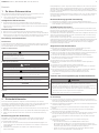 2
2
-
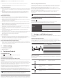 3
3
-
 4
4
-
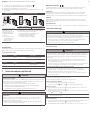 5
5
-
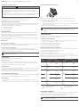 6
6
-
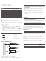 7
7
-
 8
8
-
 9
9
-
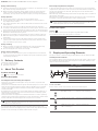 10
10
-
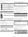 11
11
-
 12
12
-
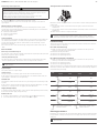 13
13
-
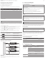 14
14
-
 15
15
-
 16
16
-
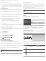 17
17
-
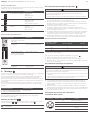 18
18
-
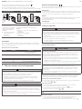 19
19
-
 20
20
-
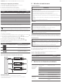 21
21
-
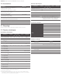 22
22
-
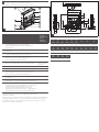 23
23
-
 24
24
-
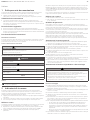 25
25
-
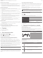 26
26
-
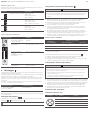 27
27
-
 28
28
-
 29
29
-
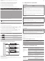 30
30
-
 31
31
-
 32
32
-
 33
33
-
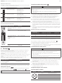 34
34
-
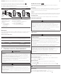 35
35
-
 36
36
-
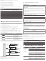 37
37
-
 38
38
-
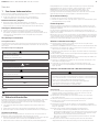 39
39
-
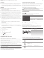 40
40
-
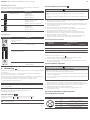 41
41
-
 42
42
-
 43
43
-
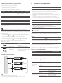 44
44
-
 45
45
-
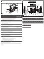 46
46
-
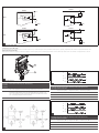 47
47
-
 48
48


AVENTICS Compact ejector, series ECD-SV Istruzioni per l'uso
- Tipo
- Istruzioni per l'uso
in altre lingue
- English: AVENTICS Compact ejector, series ECD-SV Operating instructions
- français: AVENTICS Compact ejector, series ECD-SV Mode d'emploi
- español: AVENTICS Compact ejector, series ECD-SV Instrucciones de operación
- Deutsch: AVENTICS Compact ejector, series ECD-SV Bedienungsanleitung
- svenska: AVENTICS Compact ejector, series ECD-SV Bruksanvisningar
Documenti correlati
-
AVENTICS Compact ejector, series ECD-LV Manuale del proprietario
-
-
AVENTICS ECD-IV Manuale del proprietario
-
-
-
AVENTICS Ejector EBS-ET-...-VE Manuale del proprietario
-
-
-
-