Follett MCE425A/W T Operation And Service Manual
- Categoria
- Fabbricatori di cubetti di ghiaccio
- Tipo
- Operation And Service Manual
Questo manuale è adatto anche per

MCC425A/W_S
MCE425A/W_S
ER425A/W
MCC425A/W_T
MCE425A/W_T
MFC425A/W_T
MFE425A/W_T
CP425A/W
EP425A/W
01083856R01
801 Church Lane • Easton, PA 18040, USA
Toll free (877) 612-5086 • +1 (610) 252-7301
www.follettice.com
Operation and Service Manual
MC_425A/W, MF_425A/W, _P425A/W
Ice Machines - 230 V 50 Hz, 220 V 60 Hz
Following installation, please forward this manual
totheappropriate operations person.

2 MC_425A/W, MM_425A/W, MF_425A/W, _P425A/W Ice Machines

CAUTION!
§ Do not tilt any unit further than 30° off vertical during uncrating or installation.
§ Dispenser bin area contains mechanical, moving parts. Keep hands and arms clear of this area at all times. If
access to this area is required, power to unit must be disconnected rst.
§ This appliance is not suitable for installation in an area where a water jet could be used.
§ This appliance must not be cleaned by a water jet.
§ User maintence should not be done by children without supervision.
§ Follett recommends a Follett water lter system be installed in the ice machine inlet water line (standard
capacity #00130229, high capacity #00978957, carbonless high capacity #01050442).
§ Prior to operation clean and sanitize the dispenser in accordance with instructions found in this manual.
§ Do not block right side air intake or top air exhaust.
§ This appliance should be permanently connected by a qualied person in accordance with application codes.
§ A qualied person shall provide a readily accessible disconnect device incorporated into the xed wiring.
§ If the supply cord is damaged, it must be replaced by the manufacturer, its service agent or similarly qualied
persons in order to avoid a hazard.
§ Connect to potable water supply only.
§ This appliance can be used by children aged 8 years and above and persons with reduced physical, sensory,
or mental capabilities, or lack of experience and knowledge if they have been given supervision or instruction
concerning use of the appliance in a safe way and understand the hazards involved. Children should be
supervised to ensure that they do not play with the appliance.
§ This appliance is intended to be used for household and similar applications such as staff kitchen areas
in shops, offices and other working environments; farm houses and by clients in hotels, motels and other
residential type environments; bed and breakfast type environments; catering and similar non-retail
applications.
§ WARNING! To avoid a hazard due to instability of the appliance, it must be xed in accordance with the
instructions.
§ Warranty does not cover exterior or outside installations.
§ To reduce risk of shock, disconnect power before servicing.
§ Ice is slippery. Maintain counters and oors around dispenser in a clean and ice-free condition.
§ Ice is food. Follow recommended cleaning instructions to maintain cleanliness of delivered ice.
MC_425A/W, MM_425A/W, MF_425A/W, _P425A/W Ice Machines 3

4 MC_425A/W, MM_425A/W, MF_425A/W, _P425A/W Ice Machines
Contents
Welcome to Follett. . . . . . . . . . . . . . . . . . . . . . . . . . . . . . . . . . . . . . . . . . . . . . . . . . . . . . . . . . . . . . . . . . . . . . . . . . . 5
Before you begin ............................................................................ 5
Specications .............................................................................. 6
Electrical ................................................................................ 6
Plumbing ................................................................................ 6
Ambient ................................................................................. 6
Water usage (water-cooled condenser only) .................................................... 6
Dimensions and clearances ................................................................. 7
Operation .................................................................................. 8
Cleaning/descaling and sanitizing ............................................................ 8
Weekly ................................................................................. 8
Monthly ................................................................................. 8
Semi-Annually (more often if conditions dictate) ................................................. 8
Service ................................................................................... 10
Ice machine Operation (all models) .......................................................... 10
Water system ............................................................................11
Electrical system ......................................................................... 12
Technical specications (all models) ......................................................... 14
Electrical control system schematic - 230 V 50 Hz .............................................. 16
Electrical control system schematic - 220 V 60 Hz .............................................. 17
Electrical control system operation ........................................................... 17
Refrigeration system (all models) ............................................................ 27
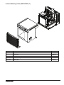
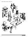
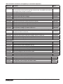
Replacement parts ......................................................................... 30
Replacement ice machine ordering matrix ..................................................... 30
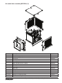
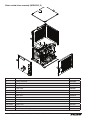
Air-cooled skins assembly (MCE425A_S) ..................................................... 31
Water-cooled skins assembly (MCE425W_S) .................................................. 32
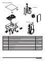
Louvered docking station (MCE425A/W_T) .................................................... 33
Evaporator ............................................................................. 34
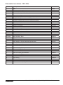
Air-cooled ice machines - 230 V 50 Hz ....................................................... 36
Air-cooled ice machines - 220 V 60 Hz ....................................................... 38
Water-cooled ice machines - 230 V 50 Hz ..................................................... 40
Water-cooled ice machines - 220 V 60 Hz ..................................................... 42
Electrical components .................................................................... 44

Welcome to Follett
Follett equipment enjoys a well-deserved reputation for excellent performance, long-term reliability and outstanding
after-the-sale support. To ensure that this equipment delivers that same degree of service, we ask that you review
the installation portion of this manual before beginning to install the unit. Our instructions are designed to help you
achieve a trouble-free installation. Should you have any questions or require technical help at any time, please call
our technical service group at (877) 612-5086 or +1 (610) 252-7301.
Note: To expedite assistance, all correspondence or communication MUST include the model number, serial number
and complete and detailed explanation of the problem.
Before you begin
After uncrating and removing all packing material, inspect the equipment for concealed shipping damage. If damage
is found, notify the shipper immediately and contact Follett LLC so that we can help in the ling of a claim,
if necessary.
Check your paperwork to determine which model you have. Follett model numbers are designed to provide
information about the type and capacity of Follett equipment. Following is an explanation of the different model
numbers in the 425 series.
MCE425ABT
Application
V – Vision
B – Bin
H – Harmony
J – Drop-in
Configuration
T – top-mount
Ice machine capacity and refrigerant
400 – 425 lbs (193 kg)/day, R404A
Ice machine series
Maestro
Voltage
E – 230 V 50 Hz
C - 220 V 60 Hz
Condenser type
A – air-cooled
W – water-cooled
Ice machine type
C – Chewblet ice
M - MicroChewblet ice
F - Flake ice
MC_425A/W, MM_425A/W, MF_425A/W, _P425A/W Ice Machines 5

Specications
Electrical
§ Each ice machine and dispenser require a separate circuit with electrical disconnect within 10 ft (6 m).
§ Equipment ground required.
§ Standard electrical – 230 V, 50 Hz, 1 phase or 220 V, 60 Hz, 1 phase
§ Connect to a dedicated circuit.
§ Maximum ice machine amperage – 5.5A.
§ Cord provided on ice machine.
Plumbing
§ 3/8" FPT water inlet
§ 3/4" MPT drain
§ 3/8" FPT condenser inlet (water-cooled condenser only)
§ 3/8" FPT condenser drain (water-cooled condenser only)
Notes:
§ Slope to drain of 1/4" per foot (6 mm per 30.4 cm run) with a 1/2" min. is recommended.
§ Water shut-off recommended within 10 feet (3 m), drain to be hard piped and insulated.
§ Separate drains for ice machine and condenser. To prevent back ow, do NOT connect drains.
§ Follett recommends a Follett water lter system be installed in the ice machine inlet water line (standard capacity
#00130229, high capacity #00978957, carbonless high capacity #01050442).
Ambient
Air temperature* 100 F/38 C max. 50 F/10 C min. (best performance below 80 F/27 C)
Water temperature
†
90 F/32 C max. 45 F/10 C min. (best performance below 70 F/21 C)
Water pressure 70 psi max. (482 kPA) 10 psi min. (68 kPA)
Condenser water
temperature
90 F/32.2 C max. 45 F/7.2 C min
Condenser water
pressure
125 psi (862 kPA) max. 10 psi (68 kPA) min.
*
Ambient air temperature is measured at the air-cooled condenser coil inlet.
†
Ambient water temperature is measured in the ice machine reservoir.
Water usage (water-cooled condenser only)
§ 0.25 gpm (0.95 L/m)@ 50 F (10 C)
§ 0.5 gpm (1.90 L/m)@ 70 F (21 C)
§ 1.25 gpm (4.73 L/m)@ 90 F (32 C)
6 MC_425A/W, MM_425A/W, MF_425A/W, _P425A/W Ice Machines

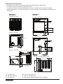
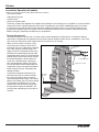
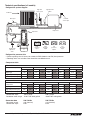
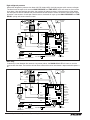
Side view — air-cooled and water-cooled
20.75" (52.7 cm)
22.75" (57.8 cm)
17.00"
(43.2 cm)
RIDE model air-cooled units only
Front view — top mount
MCE425A/W_T
MFE425A/W_T
MCE425A/W_S
ER425A/W
Side view — top mount
22.49" (57.1 cm)
21.29" (54.1 cm)
22.69" (57.6 cm)
22.46" (57.1 cm)
Back view — top mount
A
B
D
E
C
Front view — water-cooled
CONDENSER
OUTLET
10.62" (27.0 cm)
8.25" (20.9 cm)
4.81"
(12.0 cm)
2.31"
(5.7 cm)
5.25"
(13.3 cm)
C
F
E
D
A
B
Front view — air-cooled
4.81"
(12.0 cm)
2.31" (5.7 cm)
2.5" (6.4 cm)
C
F
A
B
18.88" (48 cm)
18.88" (48 cm)
2.32"
(5.9 cm)
4.40" (11.2 cm)
15.22" (38.7 cm)
11.03" (28.0 cm)
8.03" (20.4 cm)
5.03" (12.8 cm)
2.34" (6 cm)
Dimensions and clearances
§ Entire front of ice machine must be clear of obstructions/connections to allow removal.
§ 12" (30.5 cm) clearance above ice machine for service.
§ 6" (15.3 cm) minimum clearance between exhaust side of ice machine and any adjacent equipment.
§ MCE425A & ER425A – 18" (45.7 cm) minimum, 10 ft (3 m) maximum clearance between discharge and air
intake grilles.
A – 3/4" MPT drain
B – 3/8" FPT water inlet
C – Electrical cord
D – 3/8" FPT condenser inlet
E – 3/8" FPT condenser drain
F – Bin signal connection (DO NOT APPLY VOLTAGE!)
MC_425A/W, MM_425A/W, MF_425A/W, _P425A/W Ice Machines 7

Operation
Cleaning/descaling and sanitizing
Follett ice machines and dispensers, and their associated cleaning and sanitizing procedures, are designed for
use with potable water sources. The presence, or suspected presence, of infectious agents may call for additional
measures, including the replacement of components and more comprehensive disinfection measures. Follett
recommends that these cleaning and sanitizing procedures be reviewed with the appropriate infectious agent subject
matter experts to assure complete remediation.
Periodic cleaning/descaling and sanitizing of Follett’s ice machine system is required to ensure peak performance
and delivery of clean, sanitary ice. The recommended cleaning procedures that follow should be performed at least
as frequently as recommended and more often if environmental conditions dictate.
Cleaning of the condenser can usually be performed by facility personnel. Cleaning/descaling and sanitizing of
the ice machine system should be performed by your facility’s trained maintenance staff or a Follett authorized
service agent. Regardless of who performs the cleaning, it is the operator’s responsibility to see that this cleaning is
performed according to the schedule below. Service problems resulting from lack of preventive maintenance will not
be covered under the Follett warranty.
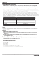
Symphony Plus Frequency
Drain Line weekly
Drain Pan/Drip Pan weekly
Exterior as needed
Condenser monthly (air-cooled only)
Ice Machine semi-annually
Transport Tube semi-annually
* Ice machine must be sanitized prior to start-up.
Weekly
The exterior may be cleaned with a stainless cleaner such as 3M* Stainless Steel Cleaner & Polish or equivalent.
* 3M is a trademark of 3M Company.
Monthly
Condenser (air-cooled ice machine only)
1. Use a vacuum cleaner or stiff brush to carefully clean condenser coils of lint and debris to ensure optimal
performance.
2. When reinstalling counter panels in front of RIDE model ice machines, be sure that ventilation louvers line
up with condenser air duct.
Semi-Annually (more often if conditions dictate)
§ A cleaning/descaling and sanitizing procedure should always include both the ice machine and bin/dispenser.
§ Icemaking system can be cleaned/descaled in place.
Cleaning & Sanitizing Tool Checklist
§ (2) 1.5 Gallon (or larger) plastic buckets
§ (2) clean cloths
§ Sanitary gloves
§ Safety Glasses
§ (2) Sani-Sponge™ (P/N 00131524 - single sponge)
§ (1 ) Packet of SafeCLEAN Plus™ (P/N 01050863 - 24 packets)
8 MC_425A/W, MM_425A/W, MF_425A/W, _P425A/W Ice Machines

CAUTION!
§ Wear rubber gloves and safety goggles (or face shield) when handling cleaner or sanitizer mixtures.
§ Use only Follett approved cleaners.
§ It is a violation of Federal law to use Solution A or Solution B in a manner inconsistent with their labeling.
§ Do not use solvents, abrasive cleaners, metal scrapers or sharp objects to clean any part of the dispenser.
SafeCLEAN Plus Solution: Mix cleaning solution of 1 gal. (3.8 L) 100 F (38 C) water and 7 oz (198 g) (one 7 oz
packet) of Follett SafeCLEAN Plus ice machine cleaner/descaler and sanitizer.
Cleaning/descaling and Sanitizing Procedure
Note: Check drains and drain cup to ensure they are open and owing freely.
1. If ice machine was running recently, ensure that the evaporator is completely free of ice before proceeding.
If there is ice in the evaporator, complete steps 2-7 using only hot water to remove the ice then begin
Cleaning/Descaling Procedure again.
2. Remove front or top cover.
3. Disconnect bin signal cable from ice machine electrical box.
4. Press CLEAN switch. The MAINTENANCE light will turn on and the machine will drain. Wait for the LOW
WATER light to turn on.
5. Remove lid from cleaning cup and ll (about 1 quart) until
SafeCLEAN Plus
solution completely lls the
reservoir. Place lid back on cup.
6. CLEANER FULL light will turn on and machine will start cleaning and sanitizing cycle then rinse three
times; this process takes approximately 15 minutes.
7. When machine is nished cleaning and sanitizing, the MAINTENANCE light will turn off.
8. Loosen phillips-head screw on nozzle connected to evaporator. Remove nozzle from evaporator side only,
leave other side of nozzle connected to transport tube.
9. Place one Sani-Sponge in remaining
SafeCLEAN Plus
solution.
10. Insert the sponge soaked in
SafeCLEAN Plus
solution into nozzle then insert a dry sponge into the nozzle.
11. Replace nozzle onto evaporator and tighten screw. Ensure drain is connected to reservoir and vent tubes
are connected to evaporator drain pan.
12. Reconnect bin signal cable. Wait for ice to push sponges through transport tube.
13. Collect sponges from ice storage bin.
14. Replace front or top cover.
15. After 10 minutes, dispense all ice and discard.
16. Clean/descale and sanitize dispenser/bin.
Exterior Cabinet
§ Clean stainless steel panels with stainless steel cleaner.
MC_425A/W, MM_425A/W, MF_425A/W, _P425A/W Ice Machines 9

Service
Ice machine Operation (all models)
Follett’s ice machine consists of four distinct functional systems:
§ Harvesting system
§ Refrigeration system
§ Water system
§ Electrical control system
These four systems work together to accomplish the production and harvesting of ice. A problem in any one of these
systems will result in improper operation of the entire ice production cycle. When troubleshooting the ice machine,
it is important to analyze the entire system operation to determine which system is not functioning properly, then
pinpoint the component within that system that is malfunctioning. Determine what corrective action must be taken
before making any adjustments or replacing any components.
The icemaking process
The Maestro Plus ice machine uses a stainless steel jacketed evaporator and operates on a continuous freezing
cycle. Water is supplied to the evaporator from the water reservoir where the water level is controlled by a oat valve.
This valve also shuts off the water supply when the ice machine is not running.
When the ice machine is running, a layer
of ice forms on the interior surface of the
evaporator. This ice is continuously removed
by a slowly rotating (10RPM) auger. The
auger carries the ice upward into the cavity
formed by the top bearing housing and the
compression loop, where it is compressed to
remove excess water. When the ice reaches
the desired hardness it rotates within the
cavity and is forced through a discharge
port and compression nozzle and into the
ice transport tube. The discharge tube and
compression nozzle are slightly restricted to
further compress the ice and produce the
desired hardness.
A solid state control board located in the
electrical box of the ice machine controls
the normal operation of the ice machine
and monitors gearmotor torque. This control
board will shut down the ice machine should
an over-torque condition occur. It is very
important that you familiarize yourself with
the operational sequences detailed in this
manual before attempting to service the ice
machine.
water
inlet
auger
compression nozzle
ice transport tube
evaporator
port
10 MC_425A/W, MM_425A/W, MF_425A/W, _P425A/W Ice Machines

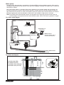
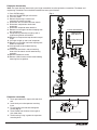
Water system
The water level in the evaporator is controlled by a ll solenoid (Fig 1) and level detecting sensors. Water sensing
rods (Fig. 2) extend down into the reservoir at the end of the evaporator assembly. The system works via electrical
conductivity as follows:
One of the longest probes is a common. When water is between any of the other probes and the common, the
PC board will sense the activation. During normal operation, the water level rises and falls between the Normal
High and Normal Low sensors. As water is consumed to make ice, the level will fall until the Normal Low sensor is
exposed, triggering the water feed solenoid on. Water will ll until the Normal High sensor is activated.
Note: The potable water dissolved solids content must be greater than 10 ppm for the water control system to
function properly. If using reverse osmosis water ltration system, ensure T.D.S level is greater than 10 ppm.
Fig. 1 Water system diagram
CLEANING CUP
WATER SUPPLY
3/8" FPT, 45-90 F (7-32 C)
10-70 PSI (69-483 KPA)
RESERVOIR FILL
SOLENOID
WASTE WATER DRAIN
3/4" FPT
WATER
RESERVOIR
EVAPORATOR
ICE
NOZZLE
DRAIN PAN
VENT
DRAIN
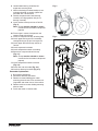
Fig. 2 Water level diagram
B
A
C
D
NORMAL OPERATING RANGE
A ALARM LOW (RED)
B COMMON (BLACK)
C NORMAL HIGH (ORANGE)
D NORMAL LOW (YELLOW)
B
A
B
A
C
D
C
D
MC_425A/W, MM_425A/W, MF_425A/W, _P425A/W Ice Machines 11

12 MC_425A/W, MM_425A/W, MF_425A/W, _P425A/W Ice Machines
Electrical system
ATTENTION!
To prevent circuit breaker overload, wait 15 minutes before restarting this unit. This allows the compressor
to equalize and the evaporator to thaw.
Normal control board operation
The PC board indicator lights provide all the information necessary to determine the machine's status. Green
indicator lights generally represent “go” or normal operation; Yellow indicators represent normal off conditions; Red
indicators generally represent alarm conditions, some of which will lock the machine off.
A ashing green light labeled POWER indicates power to the machine. All other normal operation status indicators
are covered as follows:
Ice machine disposition Operating conditions
FLASHINGON or OFF
Legend:
OFFON
1. Ice machine is making ice. 1. Normal running.
2. Ice machine is not making ice.
2. Normal time delay. When the bin lls with ice, the LOW BIN
light goes out momentarily and the refrigeration and auger
drive systems immediately shut down. (Note: The fan motor
will continue to run for 10 minutes to cool condenser) The TIME
DELAY light comes on, initiating the time delay period. When
the time delay expires, the machine will restart provided that the
LOW BIN light is on.
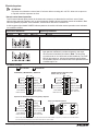
DIP Switch Settings
Sleep cycle dispense duration
OFF ON
1 2 3 4 5 6 7 8
4 5 4 5
4 5 4 5
35 s
15 s
5 s
60 s
OFF POSITION ON POSITION
Sleep cycle
enabled
Not used
Sleep cycle
dispense duration
60 min. time delay
Flush enabled*
Maint. timer OFF
OFF ON
Sleep cycle
disabled
Not used
Sleep cycle
dispense duration
20 min. time delay
Flush disabled
Maint. timer ON
1 2 3 4 5 6 7 8
Sleep cycle
enabled
Not used
Sleep cycle
dispense duration
60 min. time delay
Flush enabled
Maint. timer OFF
OFF ON
Sleep cycle
disabled
Not used
Sleep cycle
dispense duration
20 min. time delay
Flush disabled
Maint. timer ON
1 2 3 4 5 6 7 8
MCE425A/W_T, MCE425A/W_S, ER425A/W
Replacement EP425A/W installed in Symphony dispenser
Sleep cycle
enabled
Not used
Sleep cycle
dispense duration
60 min. time delay
Flush enabled
Maint. timer OFF
OFF ON
Sleep cycle
disabled
Not used
Sleep cycle
dispense duration
20 min. time delay
Flush disabled
Maint. timer ON
1 2 3 4 5 6 7 8
425A/W installed in Symphony Plus
25/50/110 CI, CT, or FB
* Flush can be enabled on Symphony CT and FB models. Flush should be disabled on Symphony CI units due to risk of internal leak if
drain line is blocked. All Symphony Plus models should be set to Flush enabled.

MC_425A/W, MM_425A/W, MF_425A/W, _P425A/W Ice Machines 13
Relay/triac output indication
Each relay on the board has an indicator light associated with its output. For example, when the relay for the water
feed solenoid is energized, the adjacent indicator light glows green.
Flushing logic
Off cycle: At the completion of off-cycle time delay, the machine checks for a cumulative one (1) hour of ice making
time since the last off-cycle ush. If the cumulative ice making time exceeds one (1) hour, the machine will open
the drain valve for 60 seconds to drain the evaporator in its entirety. It will then rell with water, ush again and rell,
and begin making ice. If the ice making time is less than 1 hour, the machine will start and begin making ice without
draining the evaporator.
Error faults
The Maestro Plus PC board monitors various operating parameters including high pressure, auger gearmotor
amperage limits, clogged drain, and low water alarm conditions. There are two types of errors namely “hard” or “soft”.
A hard error is one that shuts the machine off and will not allow restart until the reset button is pressed. Even cycling
power will not reset a hard error. A soft error can either be automatically reset should the condition rectify, or if power
is cycled. Should an error occur, consult the troubleshooting guide in this manual or a Follett service technician.
Soft errors:
Note: For all soft errors, the ice machine will remain off for 1 hour.
LO WATER: During operation, the water level cycles between the normal low and normal high sensors. Should the
water be shut off to a running machine, a soft error will occur. The error sequence is as follows: During operation,
the water level falls to the normal low sensor, and when it does the water feed solenoid is energized. If water is not
detected at the normal low sensor within 10 seconds, a soft error will occur. The machine will shut down and TIME
DELAY and LOW WATER LEDs will be lit. After time delay, the solenoid will energize and remain energized until the
water level is sufficient for restart.
HI PRESSURE: Should the refrigeration pressure rise above 425 psi, the machine will shut down and the TIME
DELAY and HIGH PRESSURE will be illuminated. After the time delay, and if the pressure has fallen back below the
reset point of 295 psi, the machine will restart and the TIME DELAY and HIGH PRESSURE will clear.
HI AMPS: The PC board monitors the amperage of the auger motor. Should the gear motor experience current draw
above the allowable 1.8A limit or no current draw (0A), the machine will shut down and the TIME DELAY and HI AMP
will be illuminated. After the time delay the machine will restart and the TIME DELAY and HI AMP will clear.
Hard error:
HI AMPS: If a second hi-amp error occurs within 1 hour of the initial hi-amp error, the ice machine will shut off and
the reset on the board must be pressed to clear the error. If a second hi-amp has occurred, the HI AMP LED only will
be illuminated.
DRAIN CLOG: The drain clog sensor, located in the evaporator drain pan will detect the presence of water just below
the top edge of the pan. If water does not properly ow out of the internal or external drain lines it will backup into the
drain pan (especially during a self-ushing purge cycle). Pressing the reset button will restart the ice machine.

14 MC_425A/W, MM_425A/W, MF_425A/W, _P425A/W Ice Machines
Technical specications (all models)
Refrigeration system diagram
condenser
filter dryer
thermostatic
expansion
valve
evaporator
high side
service port
low side
service port
high pressure
switch
compressor
high
pressure
vapor
low
pressure
vapor
high
pressure
liquid
low
pressure
liquid
Refrigeration pressure data
§ Water regulating valve is factory set at 300 ±10 PSIG (2068.4 ± 69 kPA) head pressure.
§ Readings within 10% of table values should be considered normal.
Compressor data
Air-cooled
Ambient air temperature 60 F/15.6 C 70 F/21.1 C 80 F/26.7 C 90 F/32.2 C 100 F/37.8 C
220 V 230 V 220 V 230 V 220 V 230 V 220 V 230 V 220 V 230 V
Amperage 2.65 2.25 2.77 2.36 2.89 2.46 3.01 2.57 3.13 2.68
High-side pressure (psi) 219 199 256 233 293 266 330 306 367 346
Low-side pressure (psi) 28 29 30 31 33 33 35 36 38 38
Water-cooled
Condenser water
temperature
60 F/15.6 C 70 F/21.1 C 80 F/26.7 C 90 F/32.2 C 100 F/37.8 C
220 V 230 V 220 V 230 V 220 V 230 V 220 V 230 V 220 V 230 V
Amperage 2.8 2.4 2.9 2.5 2.9 2.5 2.9 2.5 3.0 2.6
High-side pressure (psi) 290 290 291 291 292 292 292 293 293 294
Low-side pressure (psi) 31 32 31 32 32 33 32 34 33 34
Locked rotor amps 220 V: 19.6A 230 V: 18.2A
Condenser water usage: @70 F/70F: 0.26 gal/min @90 F/70F: 0.56 gal/min
Gearmotor data 220 V/60 Hz 230 V/50 Hz
Gearmotor current 1.0A (nominal) 1.3A (nominal)
Locked rotor amps 6.8A 6.8A

MC_425A/W, MM_425A/W, MF_425A/W, _P425A/W Ice Machines 15
Air-Cooled ice machine capacity/24hrs. - 220 V/60 Hz
Ambient Air Temperature F/C
Inlet Water Temperature F/C
F 60 70 80 90 100
C 16 21 27 32 38
50 454 426 398 363 328 lbs.
10 205 193 181 165 149 kg.
60 437 408 379 346 314 lbs.
16 198 185 172 157 142 kg.
70 420 390 359 330 300 lbs.
21 191 177 163 150 136 kg.
80 401 374 348 319 290 lbs.
27 182 170 158 145 132 kg.
90 381 359 337 308 280 lbs.
32 173 163 153 140 127 kg.
Air-Cooled ice machine capacity/24hrs. - 230 V/50 Hz
Ambient Air Temperature F/C
Inlet Water Temperature F/C
F 60 70 80 90 100
C 16 21 27 32 38
50 460 425 390 355 320 lbs.
10 208 193 177 161 145 kg.
60 437.5 405 372.5 340 307.5 lbs.
16 198 184 169 154 139 kg.
70 415 385 355 325 295 lbs.
21 188 175 161 147 134 kg.
80 405 375 345 315 285 lbs.
27 184 170 156 142 129 kg.
90 395 365 335 305 275 lbs.
32 179 166 152 138 125 kg.
Water-Cooled ice machine capacity/24hrs. -
220 V/60 Hz
Condenser Water Temperature F/C
Inlet Water Temperature F/C
F 60 70 80 90 100
C 16 21 27 32 38
50 454 442 431 419 408 lbs.
10 206 200 195 190 185 kg.
60 435 421 407 394 380 lbs.
16 197 191 185 179 172 kg.
70 416 400 384 368 351 lbs.
21 187 181 174 167 159 kg.
80 396 381 365 350 335 lbs.
27 180 173 166 159 152 kg.
90 375 361 346 332 318 lbs.
32 170 164 157 151 144 kg.
Water-Cooled ice machine capacity/24hrs. -
230 V/50 Hz
Condenser Water Temperature F/C
Inlet Water Temperature F/C
F 60 70 80 90 100
C 16 21 27 32 38
50 429 407 386 364 353 lbs.
10 195 185 175 165 160 kg.
60 409 389 370 350 331 lbs.
16 185 176 168 159 150 kg.
70 389 372 354 336 322 lbs.
21 176 169 161 152 146 kg.
80 370 353 337 320 304 lbs.
27 168 160 153 145 138 kg.
90 349 335 320 315 290 lbs.
32 158 152 145 143 132 kg.
Note: Nominal values - actual production may vary by ±10%.

16 MC_425A/W, MM_425A/W, MF_425A/W, _P425A/W Ice Machines
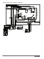
Electrical control system schematic - 230 V 50 Hz
WATER LEVELS
P17
BIN
P12
CLEAN SAFE
P11
POWER
LOW BIN
MAKING ICE
SLEEP CYCLE
TIME DELAY
LOW WATER
MAINTENANCE
SERVICE
HI AMPS
HI PRESSURE
CLEANER FULL
RESERVOIR
WATER SENSOR
MAINT.
CLEAN
HI PRS
P14
HIGH
PRESS
P
A B C D
BLACK
YELLOW
ORANGE
RED
GRN #17
BLACK #51
BLACK #23
BIN
CONTACT
CLOSURE
L1
L2/N
DISP
GND
BLACK #23
GRN-YEL #24
WHITE #25
BLACK #26
WHITE
BLUE
START
RELAY
3
4
2
YELLOW
BLACK
T.O.L.
START
RUN
FAN
FEED VALVE
DRAIN VALVE
RED #16
WHITE #121
WHITE #13
BROWN #14
BLACK #122
BLUE #07
BLACK #51
WHITE #52
COMP.
R
C
S
O.L.
C2 START
1 2 3 4 5 6 7 8 9
GREEN #53
COMPRESSOR
COMPRESSOR
ELECTRICAL
BOX
BLACK #51
WHITE #52
GREEN #53
RED #54
ORANGE #55
BLACK #56
GREEN #57
BLACK #58
BLACK #59
6
4
1
2
5
BLACK #61
WHITE #62
GREEN #63
WHITE #64
BLACK #65
BLACK #66
GREEN #67
BLACK #68
BLACK #69
C1 RUN
BLACK #66
BLACK #69
BLACK #71
#15
#04
#05
WHITE
DRAIN CLOG
SENSOR
BLACK
VIOLET
DRAIN CLOG
MODEL SELECT
SERIAL COMM
COMPRESSOR
AUGER
WATER LEVELS
HI PRS
BIN RS485
RS485 UI
CURRENT SENS
RESET
PROGRAM
P5
ICE AUX WATER AUX
D9
D8
D7
D6
D5
D4
D37
D3
D2
D18
D16
D15
D14
D13
D12
D11
D10
D1
T1
P18
P11
P13
P17
P12
P14
P16
P15
P4
T2
S1
S2
K1
P7
P8
P10
K3
1
2
6
5
P9
L1 L1L1
N N N N N N N N N
P2
P1
P21
P20
P19
P3
BLACK #01
P6
P22
D19D22D21D20
D17
D48
BLACK
BLACK

Electrical control system schematic - 220 V 60 Hz
P17-WATER LEVELS
P12-BIN
P11-CLEAN SAFE
POWER
LOW BIN
MAKING ICE
SLEEP CYCLE
TIME DELAY
LOW WATER
MAINTENANCE
SERVICE
HI AMPS
HI PRESSURE
CLEANER FULL
RESERVOIR
WATER SENSOR
MAINT.
CLEAN
HIGH
PRESS
P
A B C D
BLACK
YELLOW
ORANGE
RED
GRN #17
BLACK #51
BLACK #23
BIN
CONTACT
CLOSURE
L1
L2/N
DISP
GND
BLACK #23
GRN-YEL #24
WHITE #25
BLACK #26
FAN
FEED
VALVE
DRAIN
VALVE
RED #16
WHITE #121
WHITE #13
BROWN #14
BLACK #122
BLUE #07
BLACK #51
WHITE #52
GRN / YEL #53
#15
#04
#05
WHITE
DRAIN CLOG
SENSOR
BLACK
VIOLET
DRAIN CLOG
MODEL SELECT
COMPRESSOR
P4-AUGER
P7-RS485 UI
RESET
PROGRAM
P5
D9
D8
D7
D6
D5
D4
D37
D3
D2
D18
D16
D15
D14
D13
D12
D11
D10
D1
T1
P18
P11
P13
P12-BIN
P14-HI PRS
P15
T2
S1
S2
K1
P8-RS485
K3
1
2
6
5
P9
L1
L1
L1
N N N N N N N N N
P2
P1
P21
P20
P19
P3
BLACK #01
P6
P22
D19
D22
D21
D20
D17
D48
BLACK
BLACK
BLUE
SPLIT-PHASE MOTOR
START
RELAY
3
4
2
YEL
BLK
T.O.L.
START
RUN
WHITE
4
1
2
5
BLACK #51
WHITE #52
GRN / YEL #53
C2-START
BLACK
BLACK
C1-RUN
BLUE
BLUE
BROWN
VIOLET
GRN / YEL
COMPRESSOR
VIOLET
BLACK
GRN / YEL
GRAY
S
C
R
THERMAL
O.L.
P14-HI PRS
ICE
AUX
CURRENT
SENS
P17
WATER LEVELS
P10
SERIAL
COMM
JUNCTION
BOX
START
RELAY
GROUND TERMINALS
ON MOUNTING PLATE
Electrical control system operation
The wiring diagrams that follow illustrate the circuitry of these Follett ice machines used with ice dispensers. Both
normal operation of the ice machine (Stages 1–6) and non-normal diagnostic sequences showing torque-out
(Stages 7–10) for use in troubleshooting ice machine problems are shown.
Circuitry notes
When the ice machine is used with a dispenser it receives power from the main power supply. Disconnect the
power source before performing service. When performing electrical service, always use a meter to determine
whether or not the components being serviced are energized.
§ High pressure cutout opens at 425 PSI (2930.3 kPA) and closes at 287 PSI (1978.8 kPA)(auto reset).
§ The bin signal input to the control board in the 425A/W ice machine must only be initiated by contact closure. Do
not supply power. To run the ice machine in the workshop, use the bin signal jumper (P/N 01069095).
MC_425A/W, MM_425A/W, MF_425A/W, _P425A/W Ice Machines 17

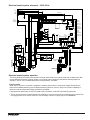
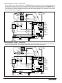
Normal operation – Stage 1 - 230V 50 Hz
Power is supplied to L1 of the control board, the POWER LED light begins ashing. The ice level bin thermostat in
the dispenser is closed and calling for ice, supplying contact closure to the control board. The LOW BIN LED will
be on. The control board will now go through the start-up sequence. The board checks the water sensors (located
in the reservoir) for continuity between the common probe (B) and the high probe (C). If continuity is not sensed,
the water ll valve (P21) is energized.
5
2
1
Start
Run
Compressor
T.O.L.
MAINTENANCE
LOW WATER
TIME DELAY
SLEEP CYCLE
MAKING ICE
LOW BIN
POWER
SERVICE
HI AMPS
HI PRESSURE
DRAIN CLOG
CLEANER FULL
High
Pressure
Switch
R
S
C
Gearmotor
Start
Relay
Start
Relay
N
L1
Fan
A B C D
Water Sensors
RESET
Fill
Valve
Drain
Valve
3
4
2
Bin T-Stat
Clean Switch
Drain Clog Sensor
P6
P21
P20
P19
P3
P22
P4
AUGER
WATER LEVELS
BIN
P11
HI PRS
L1
R
S
C
RED
WHITE
WHITE
BLACK
BROWN
BLUE
RED
BLACK YELLOW
Compressor
Electrical Box
COMPRESSOR
1 2 3 4 5 6 7 8
BLACK
N
P15
Ice Dispense Input
Normal operation – Stage 1 - 220 V 60 Hz
The 220 V 60 Hz is identical to the 230 V 50 Hz EXCEPT that the compressor output and neutral are reversed, as
shown in the diagram below. The remaining Stages show only the 230 V 50 Hz applications.
Start
Run
Compressor
MAINTENANCE
LOW WATER
TIME DELAY
SLEEP CYCLE
MAKING ICE
LOW BIN
POWER
SERVICE
HI AMPS
HI PRESSURE
DRAIN CLOG
CLEANER FULL
High
Pressure
Switch
R
S
C
Gearmotor
Start
Relay
Start
Relay
N
L1
Fan
A B C D
Water Sensors
RESET
Fill
Valve
Drain
Valve
3
4
2
Bin T-Stat
Clean Switch
Drain Clog Sensor
P6
P21
P20
P19
P3
P22
P4
AUGER
WATER LEVELS
BIN
P11
HI PRS
L1
RED
WHITE
WHITE
BLACK
BROWN
BLUE
RED
BLACK YELLOW
Compressor
Electrical Box
COMPRESSOR
1 2 3 4 5 6 7 8
BLACK
N
P15
Ice Dispense Input
5
2
1
T.O.L.
R
S
C
18 MC_425A/W, MM_425A/W, MF_425A/W, _P425A/W Ice Machines

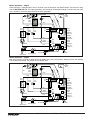
Normal operation – Stage 2
When continuity is seen between B and C, the water valve de-energizes, the AUGER output (P4) comes on along
with the MAKING ICE LED. The auger gearmotor’s start windings are energized through a current style start relay
that is pulled in by the initial high current draw of the gearmotor.
5
2
1
Start
Run
Compressor
T.O.L.
MAINTENANCE
LOW WATER
TIME DELAY
SLEEP CYCLE
MAKING ICE
LOW BIN
POWER
SERVICE
HI AMPS
HI PRESSURE
DRAIN CLOG
CLEANER FULL
High
Pressure
Switch
R
S
C
Gearmotor
Start
Relay
Start
Relay
N
L1
Fan
A B C D
Water Sensors
RESET
Fill
Valve
Drain
Valve
3
4
2
Bin T-Stat
Clean Switch
Drain Clog Sensor
P6
P21
P20
P19
P3
P22
P4
AUGER
WATER LEVELS
BIN
P11
HI PRS
L1
R
S
C
RED
WHITE
WHITE
BLACK
BROWN
BLUE
RED
BLACK YELLOW
Compressor
Electrical Box
COMPRESSOR
1 2 3 4 5 6 7 8
BLACK
N
P15
Ice Dispense Input
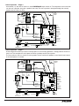
Normal operation – Stage 3
After the initial high current draw drops off, the gearmotor start relay contacts open, dropping out the start winding.
The condenser fan output (P3) comes on 0.5 seconds later.
5
2
1
Start
Run
Compressor
T.O.L.
MAINTENANCE
LOW WATER
TIME DELAY
SLEEP CYCLE
MAKING ICE
LOW BIN
POWER
SERVICE
HI AMPS
HI PRESSURE
DRAIN CLOG
CLEANER FULL
High
Pressure
Switch
R
S
C
Gearmotor
Start
Relay
Start
Relay
N
L1
Fan
A B C D
Water Sensors
RESET
Fill
Valve
Drain
Valve
3
4
2
Bin T-Stat
Clean Switch
Drain Clog Sensor
P6
P21
P20
P19
P3
P22
P4
AUGER
WATER LEVELS
BIN
P11
HI PRS
L1
R
S
C
RED
WHITE
WHITE
BLACK
BROWN
BLUE
RED
BLACK YELLOW
Compressor
Electrical Box
COMPRESSOR
1 2 3 4 5 6 7 8
BLACK
N
P15
Ice Dispense Input
MC_425A/W, MM_425A/W, MF_425A/W, _P425A/W Ice Machines 19

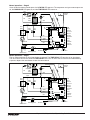
Normal operation – Stage 4
One second (1 s) after the fan comes on, the COMPRESSOR output comes on. The compressor circuit uses both
run and start capacitors along with a potential start relay. The start capacitor in energized through the normally
closed contacts of the start relay.
5
2
1
Start
Run
Compressor
T.O.L.
MAINTENANCE
LOW WATER
TIME DELAY
SLEEP CYCLE
MAKING ICE
LOW BIN
POWER
SERVICE
HI AMPS
HI PRESSURE
DRAIN CLOG
CLEANER FULL
High
Pressure
Switch
R
S
C
Gearmotor
Start
Relay
Start
Relay
N
L1
Fan
A B C D
Water Sensors
RESET
Fill
Valve
Drain
Valve
3
4
2
Bin T-Stat
Clean Switch
Drain Clog Sensor
P6
P21
P20
P19
P3
P22
P4
AUGER
WATER LEVELS
BIN
P11
HI PRS
L1
R
S
C
RED
WHITE
WHITE
BLACK
BROWN
BLUE
RED
BLACK YELLOW
Compressor
Electrical Box
COMPRESSOR
1 2 3 4 5 6 7 8
BLACK
N
P15
Ice Dispense Input
Normal operation – Stage 5
As the compressor comes up to normal running speed, its start winding generates a voltage potential across the
relay’s coil. This energizes the coil to open the contact and drop out the start capacitor.
The ice machine is now in a normal ice making mode. The ice machine will produce ice until the bin level control
in the ice dispenser is satised.
5
2
1
Start
Run
Compressor
T.O.L.
MAINTENANCE
LOW WATER
TIME DELAY
SLEEP CYCLE
MAKING ICE
LOW BIN
POWER
SERVICE
HI AMPS
HI PRESSURE
DRAIN CLOG
CLEANER FULL
High
Pressure
Switch
R
S
C
Gearmotor
Start
Relay
Start
Relay
N
L1
Fan
A B C D
Water Sensors
RESET
Fill
Valve
Drain
Valve
3
4
2
Bin T-Stat
Clean Switch
Drain Clog Sensor
P6
P21
P20
P19
P3
P22
P4
AUGER
WATER LEVELS
BIN
P11
HI PRS
L1
R
S
C
RED
WHITE
WHITE
BLACK
BROWN
BLUE
RED
BLACK YELLOW
Compressor
Electrical Box
COMPRESSOR
1 2 3 4 5 6 7 8
BLACK
N
P15
Ice Dispense Input
20 MC_425A/W, MM_425A/W, MF_425A/W, _P425A/W Ice Machines
La pagina si sta caricando...
La pagina si sta caricando...
La pagina si sta caricando...
La pagina si sta caricando...
La pagina si sta caricando...
La pagina si sta caricando...
La pagina si sta caricando...
La pagina si sta caricando...
La pagina si sta caricando...
La pagina si sta caricando...
La pagina si sta caricando...
La pagina si sta caricando...
La pagina si sta caricando...
La pagina si sta caricando...
La pagina si sta caricando...
La pagina si sta caricando...
La pagina si sta caricando...
La pagina si sta caricando...
La pagina si sta caricando...
La pagina si sta caricando...
La pagina si sta caricando...
La pagina si sta caricando...
La pagina si sta caricando...
La pagina si sta caricando...
La pagina si sta caricando...
La pagina si sta caricando...
La pagina si sta caricando...
La pagina si sta caricando...
-
 1
1
-
 2
2
-
 3
3
-
 4
4
-
 5
5
-
 6
6
-
 7
7
-
 8
8
-
 9
9
-
 10
10
-
 11
11
-
 12
12
-
 13
13
-
 14
14
-
 15
15
-
 16
16
-
 17
17
-
 18
18
-
 19
19
-
 20
20
-
 21
21
-
 22
22
-
 23
23
-
 24
24
-
 25
25
-
 26
26
-
 27
27
-
 28
28
-
 29
29
-
 30
30
-
 31
31
-
 32
32
-
 33
33
-
 34
34
-
 35
35
-
 36
36
-
 37
37
-
 38
38
-
 39
39
-
 40
40
-
 41
41
-
 42
42
-
 43
43
-
 44
44
-
 45
45
-
 46
46
-
 47
47
-
 48
48


Follett MCE425A/W T Operation And Service Manual
- Categoria
- Fabbricatori di cubetti di ghiaccio
- Tipo
- Operation And Service Manual
- Questo manuale è adatto anche per
in altre lingue
- English: Follett MCE425A/W T
Documenti correlati
Altri documenti
-
 Arktic 299814 Manuale utente
-
 SIMAG SDE18 Manuale del proprietario
-
 SIMAG SDE24 Manuale del proprietario
-
Manitowoc Ice G0200 G0400 Guida d'installazione
-
Makita DFV215A Manuale utente
-
Bartscher 104204 Istruzioni per l'uso
-
Sub-Zero 5230780 Manuale utente
-
Maytag CAFF22 Guida utente
-
Ugolini MT Manuale utente
-


