AJA OG-FS-Mini Installation and Operation Guide
- Categoria
- Apparecchiature musicali supplementari
- Tipo
- Installation and Operation Guide

OG-FS-Mini
Frame Synchronizer
Version 1.0
Published September 4, 2019
Installation and Operation Guide

OG-FS-Mini Frame Synchronizer v1.0 2 www.aja.com
Notices
Trademarks
AJA® and Because it matters.® are registered trademarks of AJA Video Systems, Inc.
for use with most AJA products. AJA™ is a trademark of AJA Video Systems, Inc. for
use with recorder, router, software and camera products. Because it matters.™ is a
trademark of AJA Video Systems, Inc. for use with camera products.
CION®, Corvid Ultra®, lo®, Ki Pro®, KONA®, KUMO®, ROI® and T-Tap® are registered
trademarks of AJA Video Systems, Inc.
AJA Control Room™, KiStor™, Science of the Beautiful™, TruScale™, TruZoom™,
V2Analog™ and V2Digital™ are trademarks of AJA Video Systems, Inc.
All other trademarks are the property of their respective owners.
Copyright
Copyright © 2019 AJA Video Systems, Inc. All rights reserved. All information in
this manual is subject to change without notice. No part of the document may be
reproduced or transmitted in any form, or by any means, electronic or mechanical,
including photocopying or recording, without the express written permission of AJA
Video Systems, Inc.
Contacting AJA Support
When calling for support, have all information at hand prior to calling. To contact AJA
for sales or support, use any of the following methods:
Telephone +1.530.271.3190
FAX +1.530.271.3140
Web https://www.aja.com
Support Email suppor[email protected]
Sales Email [email protected]

OG-FS-Mini Frame Synchronizer v1.0 3 www.aja.com
Contents
Notices . . . . . . . . . . . . . . . . . . . . . . . . . . . . . . . . . . . . . .2
Trademarks . . . . . . . . . . . . . . . . . . . . . . . . . . . . . . . . . . . . . . . . . . . 2
Copyright . . . . . . . . . . . . . . . . . . . . . . . . . . . . . . . . . . . . . . . . . . . . 2
Contacting AJA Support . . . . . . . . . . . . . . . . . . . . . . . . . . . . . . . . . . . 2
Chapter 1 – Introduction . . . . . . . . . . . . . . . . . . . . . . . . . . .4
Overview. . . . . . . . . . . . . . . . . . . . . . . . . . . . . . . . . . . . . . . . . . . . .4
Features. . . . . . . . . . . . . . . . . . . . . . . . . . . . . . . . . . . . . . . . . . . . 4
Video Formats. . . . . . . . . . . . . . . . . . . . . . . . . . . . . . . . . . . . . . . .5
Block Diagram . . . . . . . . . . . . . . . . . . . . . . . . . . . . . . . . . . . . . . . . . 5
openGear and AJA. . . . . . . . . . . . . . . . . . . . . . . . . . . . . . . . . . . . . . .5
I/O Connections . . . . . . . . . . . . . . . . . . . . . . . . . . . . . . . . . . . . . . . . 6
Signal Indicators on the OG-FS-Mini Card . . . . . . . . . . . . . . . . . . . . . . 6
Signal Indicators in the DashBoard Control System . . . . . . . . . . . . . . . . 6
Frame Sync Mode Example . . . . . . . . . . . . . . . . . . . . . . . . . . . . . . . . . 8
Setup . . . . . . . . . . . . . . . . . . . . . . . . . . . . . . . . . . . . . . . . . . . . . 8
Procedure. . . . . . . . . . . . . . . . . . . . . . . . . . . . . . . . . . . . . . . . . . .8
Conversion Mode Discussion and Examples . . . . . . . . . . . . . . . . . . . . . . 8
Upconvert Mode . . . . . . . . . . . . . . . . . . . . . . . . . . . . . . . . . . . . . . 8
Downconvert Mode . . . . . . . . . . . . . . . . . . . . . . . . . . . . . . . . . . . . 9
SD Aspect Ratio Convert . . . . . . . . . . . . . . . . . . . . . . . . . . . . . . . . 11
User Controls . . . . . . . . . . . . . . . . . . . . . . . . . . . . . . . . . . . . . . . . . 12
DIP Switches . . . . . . . . . . . . . . . . . . . . . . . . . . . . . . . . . . . . . . . . 12
DashBoard Control System. . . . . . . . . . . . . . . . . . . . . . . . . . . . . . . 12
Installation. . . . . . . . . . . . . . . . . . . . . . . . . . . . . . . . . . . . . . . . . . . 12
Summary . . . . . . . . . . . . . . . . . . . . . . . . . . . . . . . . . . . . . . . . . . 12
Unpacking . . . . . . . . . . . . . . . . . . . . . . . . . . . . . . . . . . . . . . . . . 13
Rear OG-FS-Mini Card Installation . . . . . . . . . . . . . . . . . . . . . . . . . . 13
Front OG-FS-Mini Card Installation. . . . . . . . . . . . . . . . . . . . . . . . . . 14
Cabling . . . . . . . . . . . . . . . . . . . . . . . . . . . . . . . . . . . . . . . . . . . 15
Chapter 2 – Operation . . . . . . . . . . . . . . . . . . . . . . . . . . . .16
Default Operational Settings . . . . . . . . . . . . . . . . . . . . . . . . . . . . . . . 16
Using DIP Switches to Control the OG-FS-Mini . . . . . . . . . . . . . . . . . . . . 16
General Conguration DIP Switches . . . . . . . . . . . . . . . . . . . . . . . . . 16
Reference Selection DIP Switches . . . . . . . . . . . . . . . . . . . . . . . . . . 18
Using the DashBoard Control System. . . . . . . . . . . . . . . . . . . . . . . . . . 18
Requirements . . . . . . . . . . . . . . . . . . . . . . . . . . . . . . . . . . . . . . . 18
Control Interface Basic Components . . . . . . . . . . . . . . . . . . . . . . . . 18
Card Tab Screen . . . . . . . . . . . . . . . . . . . . . . . . . . . . . . . . . . . . . . 19
Status Tab Screen. . . . . . . . . . . . . . . . . . . . . . . . . . . . . . . . . . . . . 20
Video Tab Screen . . . . . . . . . . . . . . . . . . . . . . . . . . . . . . . . . . . . . 20
HDMI Tab Screen . . . . . . . . . . . . . . . . . . . . . . . . . . . . . . . . . . . . . 23
Audio Tab Screen . . . . . . . . . . . . . . . . . . . . . . . . . . . . . . . . . . . . . 24
Setup Tab Screen . . . . . . . . . . . . . . . . . . . . . . . . . . . . . . . . . . . . . 25
Upload Screen. . . . . . . . . . . . . . . . . . . . . . . . . . . . . . . . . . . . . . . 26
Rebooting . . . . . . . . . . . . . . . . . . . . . . . . . . . . . . . . . . . . . . . . . 28
Appendix A – Specications . . . . . . . . . . . . . . . . . . . . . . . . 29
OG-FS-Mini Tech Specs. . . . . . . . . . . . . . . . . . . . . . . . . . . . . . . . . . . 29
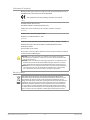
Appendix B – Safety and Compliance . . . . . . . . . . . . . . . . . . 33
Warranty and Liability Information . . . . . . . . . . . . . . . . . . . .42
Limited Warranty on Hardware. . . . . . . . . . . . . . . . . . . . . . . . . . . . . . 42
Limitation of Liability . . . . . . . . . . . . . . . . . . . . . . . . . . . . . . . . . . . . 43
Governing Law and Language; Your Rights. . . . . . . . . . . . . . . . . . . . . . 43
Index. . . . . . . . . . . . . . . . . . . . . . . . . . . . . . . . . . . . . . .44

OG-FS-Mini Frame Synchronizer v1.0 4 www.aja.com
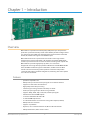
Chapter 1 – Introduction
Overview
OG-FS-Mini is an openGear broadcast quality utility frame sync that packs the
production-proven functionality and all of the reliability of AJA’s leading FS frame
sync technology into an OG card supporting frame synchronization of untimed
3G-SDI, HD, and SD video signals at an affordable price.
OG-FS-Mini allows users to synchronize and convert a wide range of video
formats to their house standard with a 3G-SDI input and output, HDMI output,
and two 3-pin terminal block connectors for balanced analog audio outputs. The
OG-FS-Mini also provides high quality up, down, cross-conversion.
Designed for use in high-density openGear’s 2RU frames and AJA’s OG-X-FR 2RU
frame, DashBoard Software support on Windows®, macOS® and Linux offers
remote control and monitoring of the openGear architecture and provides
convenient and industry-standard configuration, monitoring and control options
over a PC or local network.
Features
• openGear compatible card
• Utility frame sync function times input signals to an external reference
• Supports bi-level and tri-level references
• High quality 10-bit video processing
• Low latency processing, nominal video delay of 1 frame
• Freeze (on input signal loss) to black or last good frame
• Supports 1080p, 1080i, 720p, 625i, 525i, and SDI input signals
• Simultaneous SDI and HDMI outputs
• 16-channel embedded SDI audio I/O
• 8-channel HDMI output audio
• 2x 3-Pin terminal block connectors for analog audio output (included)
• Utility frame rate conversion
• Supports 3:2 pulldown
• Up, down, cross conversion between 3G, HD and SD video formats
• AFD input detection, down-convert control

OG-FS-Mini Frame Synchronizer v1.0 5 www.aja.com
• Remote conguration through DashBoard Control System for an openGear
Frame
• Rear I/O card included
• Compatible with OG-X-FR, OG3 and DFR-8321 openGear frames
• Five year warranty
NOTE: OG-FS-Mini converts 3G-SDI Level A formats only. It does not input or output
3G-SDI Level B.
Video Formats
The OG-FS-Mini provides utility frame rate conversion within the same frame
rate family as the input frame rate. If a reference is provided, it must be in the
same frame rate hierarchy as the input video (e.g., 23.98/29.97/59.94, 25/25, or
24/30/60).
Block Diagram
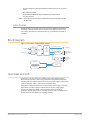
Figure 1. OG-FS-Mini, Simplified Block Diagram
Up,
Down,
and
Cross
Converter
Audio
D/A
Video
Audio
HDMI
Transmitter
Video with Embedded Audio
2-Channel
Analog Audio
Output
HDMI Output
with Embedded
Audio
SDI Input
SDI Output
SDI
Receiver
Re
ference Input Genlock
Frame
Sync
Control
DIP Switch
User Interface
DashBoard
openGear and AJA
openGear is an open-architecture, modular frame system designed by Ross
Video and supported by a diverse range of terminal equipment manufacturers,
including AJA. Ross Video manufactures the frames, power supplies and network
cards for openGear. AJA is a reseller of the openGear frames.
AJA Video is a leading manufacturer of video interface technologies, converters,
digital video recording solutions and professional cameras, bringing high-
quality, cost-effective products to the professional, broadcast and post-
production markets. AJA products, including openGear cards, are designed and
manufactured at our facilities in Grass Valley, California.

OG-FS-Mini Frame Synchronizer v1.0 6 www.aja.com
I/O Connections
Figure 2. I/O Connections for the OG-FS-Mini
SDI Input
BNC (J1)
Analog Audio
Output L
Analog Audio
Output R
HDMI Output
(inactive)
(inactive)
(inactive)
SDI Output
BNC (J2)
Reference
Input
BNC (J3)
Each 3-pin analog audio connector carries one channel of analog audio output.
Signal Indicators on the OG-FS-Mini Card
Located at the upper front area of the OG-FS-Mini card, the HD Lock and SD Lock
LEDs work in combination to indicate the type of signal detected.
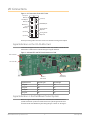
Figure 3. Indicator LEDs and DIP Switch Locations on Card
HD Lock LED
SD Lock LED
Reference
DIP Switch
General
DIP Switch
Signal Detected HD Lock Light SD Lock Light
No Signal O O
SD Signal O On
HD Signal On O
3G Signal On On
Signal Indicators in the DashBoard Control System
When the signal is either not present or is not locked, the DashBoard Control
System shows both a yellow Card State alarm and a yellow Signal State alarm
under the Status tab. Additionally, the SDI Signal Type is shown as "No Signal."

OG-FS-Mini Frame Synchronizer v1.0 7 www.aja.com
When the Add 3:2 Pulldown control has been turned on (indicated by a check
mark), and the output frame rates are not the same as the input rates of 23.98 and
24.00, the DashBoard Control System displays a yellow Card State and a yellow
Signal State with a "Pulldown Active" alarm warning.
When a signal is present and locked, the DashBoard Control System shows a
green Card State and a green Signal State under the Status tab. The SDI Signal
Type is also indicated (for example, "3G-SDI").
NOTE: Alarms always show the highest priority alarm first. When that alarm condition is
resolved, the next alarm/warning condition will display, etc.

OG-FS-Mini Frame Synchronizer v1.0 8 www.aja.com
Frame Sync Mode Example
The following section provides an example of how to set up the OG-FS-Mini to
ensure the frame sync function is working correctly.
Setup
Ensure that the OG-X-FR or other openGear-compatible 2RU frame is powered up
and connected to an appropriate network cable to be able to communicate with
the DashBoard Control System. (See "Using the DashBoard Control System" on page
18 for details.)
Procedure
1. Install the OG-FS-Mini card and rear connector into the OG-X-FR openGear
frame (see "Installation" on page 12 for installation details).
2. Launch the DashBoard application.
3. In the left panel showing the basic tree view of frames and cards, double-
click the slot and card name listed corresponding to your OG-FS-Mini.
• A window opens in DashBoard showing the OG-FS-Mini card and parameter
controls.
• By default the OG-FS-Mini is congured to operate genlocked to an external
reference signal.
• Under the Status tab in DashBoard, the Signal State indicates "Not Locked"
with a yellow alarm indicator, and the Reference Signal indicates "No Ref."
4. Connect the appropriate sync reference signal to the OG-FS-Mini Ref In
BNC. (See Figure 2. "I/O Connections for the OG-FS-Mini" on page 6 for the
location of the Ref In BNC.)
• The Reference Signal in DashBoard indicates the signal type (for example,
1080i59.94).
• However, because the OG-FS-Mini is still not receiving a compatible video
input, "No Video" will be reported for the Input Signal on DashBoard, and
the Signal State is "Not Locked" with a yellow alarm indicator.
5. Connect a 1080p59.94 SDI video source to the OG-FS-Mini SDI In BNC on the
BNC rear connector card.
• DashBoard will report 1080p59.94 for the Input Signal, and the Signal State
reports "OK" with a green alarm indicator.
6. From the Video tab, set the Output Format to 1080p (high).
7. Conrm that DashBoard shows that the Output Signal is reporting the
correct signal (in this example, 1080p59.94).
This workflow confirms that the OG-FS-Mini powers up successfully and that the
SDI video output is synchronized with the Reference Input.
Conversion Mode Discussion and Examples
Upconvert Mode
The OG-FS-Mini allows you to select the type of Upconversion performed on an
SD source input. This mode is in effect only when the input is SD (525i or 625i) and
the selected output format is HD (720p, 1080i, or 1080p).

OG-FS-Mini Frame Synchronizer v1.0 9 www.aja.com
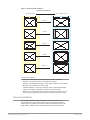
Figure 4. Upconvert Mode Examples
Upconvert Illustrations
Full Screen
4:3 Pillar
LB to Full
14:9 Pillar
Wide Zoom
16
9
4
3
4:3 Upconverts To These displays on 16:9
Selection Description
• Full Screen – 4x3 image is stretched horizontally to ll a 16x9 frame.
• 4x3 Pillar – 4x3 image at center screen with black sidebars.
• LB to Full – 4x3 letterboxed image is scaled to t horizontally in a 16x9 frame.
Black bars top and bottom are cropped o.
• 14x9 Pillar (default) – 4x3 image is scaled to create a 14x9 image with black
sidebars and slightly cropping top and bottom of original image.
• Wide Zoom – A combination of scaling and stretching is used to t to a 16x9
frame. Slight cropping of top and bottom and a small aspect ratio change.
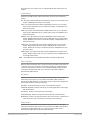
Downconvert Mode
This mode determines the type of Downconversion performed on the
selected HD source input. See the following Downconvert Illustrations for
Downconversion examples. This mode is in effect only when the input is HD
(720p, 1080i, or 1080p) and the selected output format is SD (525i or 625i).

OG-FS-Mini Frame Synchronizer v1.0 10 www.aja.com
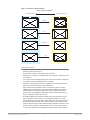
Figure 5. Downconvert Mode Example
16
9
Downconvert Illustrations
Anamorphic
Letterbox
4
3
16:9 Downconverts To These displays on 4:3
Crop
14:9
Selection Description
• Letterbox – Image is reduced with black top and bottom added to image area,
with the aspect ratio preserved.
• Crop (default) – Image is cropped to t new screen size.
• Anamorphic – HD image is converted to full-screen SD with a 16x9 aspect ratio
(anamorphic).
• 14:9 – Image is reduced slightly with aspect ratio preserved. Black is added top
and bottom, and the left and right sides are cropped.
• Auto AFD – Automatically selects the best Downconvert mode based on the
input video's Active Format Description (AFD) code.
Active Format Description (AFD) codes are carried in the vertical ancillary
(VANC) portion of HD SDI video signals, specified in SMPTE 2016 as follows:
“AFD information is intended to guide DTV receivers and/or intermediate
professional video equipment regarding the display of video of one aspect
ratio on a display of another aspect ratio.”
In the OG-FS-Mini Downconverter, the AFD code on the video input can be
used to guide the Downconverter in choosing which mode to use to best
display the important content of the16:9 HD input video on the 4:3 SD output.
For example, if the input AFD code is 10 (Full Frame), it means that the input
video has important picture information throughout the full 16:9 frame, so the
Downconverter should use Letterbox mode to be sure none of the content
is cropped off. An AFD code of 9 (Pillarbox) says that the input video only has

OG-FS-Mini Frame Synchronizer v1.0 11 www.aja.com
content within the center 4:3 area of the picture (usually because it originally
came from an Upconverted SD signal) so the Downconverter Crop mode
would be the best choice. There are 16 possible HD AFD codes, of which 8 are
in common use. The OG-FS-Mini does not process or use SD AFD codes.
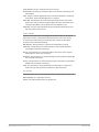
SD Aspect Ratio Convert
This mode selects the type of SD-to-SD Aspect Ratio Conversion (ARC) performed
on an incoming selected SD source. This mode is in effect only when the input
and output are both SD (525i or 625i). (In Europe 16:9 anamorphic video is also
known as “wide screen” video.)
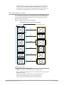
Figure 6. SD Aspect Ratio Conversion Examples
SD Aspect Ratio Conversion Illustrations
H Crop
Pillarbox
V Crop
14:9
Off
(no conversion)
Letterbox
4
3
4:3 Converts To These displays on 4:3
Selection Descriptions
• O–Turns aspect ratio conversion O.
• Letterbox–Converts 16:9 Anamorphic video to Letterbox video.
• H Crop–Converts 16:9 Anamorphic video to 4:3 Standard video (crops left and
right edges of video).
• Pillarbox–Converts 4:3 Standard video to 16:9 Anamorphic video.
• V Crop–Converts Letterbox video to 16:9 Anamorphic video.
• 14:9–Converts 16:9 Anamorphic video to 14:9 Cropped video.

OG-FS-Mini Frame Synchronizer v1.0 12 www.aja.com
User Controls
The OG-FS-Mini can be inserted right out of the box into an openGear frame
and immediately be used for many applications, since it is designed to recognize
inputs and perform standard actions automatically. However, you can also
manually configure the OG-FS-Mini using either of two methods:
• Local conguration through DIP switches on the card, or
• Remote conguration through the DashBoard Control System for an
openGear Frame.
DIP Switches
The OG-FS-Mini has two DIP switch modules mounted on the card. The left
General DIP switch module can be used for general card configuration, and to
enable remote configuration using DashBoard. The right Reference DIP switch is
used for configuring the card's reference (see Figure 3 on page 6).
The General DIP switch #1 is a “Local/Remote” switch. When in “Local” mode, the
remaining DIP switches support a subset of the user controls, and DashBoard
displays only the Card and Status tabs and cannot be used for configuration.
For more details, refer to "Using DIP Switches to Control the OG-FS-Mini" on page
16.
DashBoard Control System
The DashBoard Control System, created by Ross Video, provides a control
interface between Windows, macOS and Linux computers and the cards installed
in an openGear frame. DashBoard operates through TCP/IP communication
and requires an Ethernet connection between the controlling computer and an
openGear frame.
For details about acquiring and using the DashBoard Control System, refer to
"Using the DashBoard Control System" on page 18.
Installation
Summary
Installing an OG-FS-Mini card into an OG-X-FR openGear frame consists of the
following steps:
• Install the Rear Panel onto the back of the frame corresponding to the slot pair
you will be using for the OG-FS-Mini card.
• Insert the OG-FS-Mini card into the frame in the right (even numbered) slot of
the pair.
• Connect the BNC, HDMI and audio cabling to the Rear Panel.
ESD Susceptibility - Static discharge can cause serious damage to sensitive
semiconductor devices. Avoid handling circuit boards in high static
environments such as carpeted areas, and when wearing synthetic ber clothing.
Always exercise proper grounding precautions when working on circuit boards
and related equipment.

OG-FS-Mini Frame Synchronizer v1.0 13 www.aja.com
Unpacking
Unpack each openGear product you received from the shipping container and
ensure that all items are included. If any items are missing or damaged, contact
your sales representative or AJA directly.
Parts List
Quantity Description
1 OG-FS-Mini Front Card in ESD bag
1 BNC Rear Card
2 WECO mating connectors, part number
107654-00
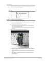
Rear OG-FS-Mini Card Installation
1. Ensure that the frame is properly installed.
2. Locate the card frame slot on the rear of the openGear frame into which you
wish to install the openGear card.
NOTE: An OG-FS-Mini card occupies two slots in the frame.
3. Using a Phillips screwdriver, unscrew the top screw from the desired blank
rear plate and remove the rear plate.
4. Seat the bottom of the Rear Card in the seating slot at the base of the frame
back plane.
Figure 7. Rear Card Inserting Into Frame Seating Slot
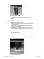
5. Align the top screw of the Rear Card with the screw hole on the top edge of
the frame back plane.
6. Ensure the Rear Card aligns with the desired card slot before tightening the
screw.
7. Using a Phillips screwdriver, fasten the Rear Card to the frame back plane.
Do not over tighten.

OG-FS-Mini Frame Synchronizer v1.0 14 www.aja.com
Figure 8. Rear Card Inserted Into Frame Seating Slot
8. Ensure proper frame cooling and ventilation by having all rear frame slots
covered with rear modules or blank metal plates if plates are not pre-
installed.
Front OG-FS-Mini Card Installation
1. Open the openGear frame door as follows:
A. Gently pull the side door tabs towards the center of the door, releasing the
door from the frame.
B. Using both hands, pull the door towards you. The door extender arms
prevent the door from falling.
2. Locate the Rear Card you installed as described above. The interior slot
number is dependent on the slot combinations into which you installed the
Rear Card. This allows adequate spacing to avoid damaging the card, the
cards installed in the neighboring slots, or both.
3. Hold the card by the edges and carefully align the card edges with the rails
inside the frame. The slots are numbered starting from the left-most slot
when facing the frame front.
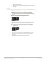
IMPORTANT: OG-FS-Mini cards are installed into the right (even numbered) slot of the
pair in order to connect with the rear panel.
4. Fully insert the card into the frame until the card is properly seated in the
Rear Card.
Figure 9. OG-FS-Mini card inserted Into Right Slot
5. Close the frame door as follows:

OG-FS-Mini Frame Synchronizer v1.0 15 www.aja.com
A. Slide the door into the frame.
B. Pull and release the door tabs to ensure the frame door is securely locked
to the frame.
Cabling
Refer to "I/O Connections for the OG-FS-Mini" on page 6 to identify the input
and output signal connectors.
Two WECO audio mating connectors are included with each OG-FS-Mini.
1. Insert connecting audio wires into their corresponding holes from the rear
(Figure 10).
Figure 10. Rear view of the WECO mating audio connector
2. Tighten the screws on the other side of the audio mating connector (Figure
11).
Figure 11. Front view of the WECO mating audio connector showing the
tightening screws
3. After you have secured the wiring for each WECO mating audio connector,
connect them to the audio output connectors on the rear panel of the
OG-FS-Mini.
4. Add tie wraps around the audio connectors for strain relief.

OG-FS-Mini Frame Synchronizer v1.0 16 www.aja.com
Chapter 2 – Operation
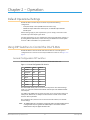
Default Operational Settings
The OG-FS-Mini converter ships from the factory with the following
configuration:
• Local (DIP switch) control (DashBoard shows status only).
• 1080i59.94 output with NTSC related inputs, or 1080i50 output with PAL
related inputs.
If these settings apply to your requirements, you can simply connect the video
and audio input and output signal cables.
For other applications, you can configure the card using its DIP switch settings, or
by setting Remote (DIP switch) control and using the DashBoard Control System
and a PC or Mac networked to an openGear frame.
Using DIP Switches to Control the OG-FS-Mini
The OG-FS-Mini has two sets of DIP switches. The first set is used for general
configuration. The second set is used only for Reference selection. See Figure 3 on
page 6.
General Configuration DIP Switches
The General DIP Switch module is located on the left side of the card.
Figure 12. General Configuration DIP Switches
1 CONTROL LOCAL REMOTE
2 SD/HD HD SD
3 1080/720 1080 720
4 FMT0 0 1
5 FMT1 0 1
6 3:2 OFF ON
7 SIDEB UP FULL
8 LTRBX DN FULL
The default DIP switch positions are all in the left position. The default settings
result in an output of 1080i59.94 with NTSC related inputs and 1080i50 with PAL
related inputs.
For 1080p 23.98/1080PsF 23.98 inputs, the input can be converted to 720p 23.98,
1080p 23.98, 1080i 59.94, or 1080p 59.94. The latter two would use the 3:2 DIP
switch to add 3:2 pulldown.
The compliance label, found on the card next to the DIP switches, lists the DIP
switch settings.
NOTE: The HDMI output does not support "PsF" formats. When the Video Output Format
is configured for PsF, the signal on the HDMI output is converted to interlace.
HDMI monitors may not support all frame rates.

OG-FS-Mini Frame Synchronizer v1.0 17 www.aja.com
NOTE: OG-FS-Mini converts 3G-A formats only. It does not accept 3G-B input or produce
3G-B output.
General Configuration DIP Switch Settings
The functions of the general configuration DIP switches and what they control are
described in the following tables.
Table 1. General Configuration DIP Switch Setting Descriptions
SWITCH FUNCTION DIP Set LEFT (default) DIP Set RIGHT
1 Control Selects LOCAL (DIP),
and blocks DashBoard
conguration control.
When in “Local” mode, the
remaining DIP switches will
support a subset of the user
controls.
Selects REMOTE (DashBoard),
and disables DIP switches 2-8.
When in “Remote” mode,
the normal DashBoard non-
volatile registers (as last set),
control the unit.
2 HD/SD Selects HD output mode. Selects SD output mode.
3 1080/720 (HD mode only) Selects 1080 output. Selects 720 output.
4 & 5 Alternate HD formats These two DIP switches (FMT0, FMT1) act together to select
alternate HD output formats. Zero (0) is Left position, one (1) is
Right position.
See Table 2 below for setting information.
6 3:2 Conversion (23.98/24
inputs only)
3:2 conversion is OFF.
A 23.98/24 fps input results in
a 23.98/24 fps output.
3:2 conversion is ON.
A 23.98/24 fps input results in
either a 29.97/30 or 59.94/60
fps output.
7 Up Conversion Sets upconversion to Sidebar
(SIDEB).
Sets upconversion to Full
screen (FULL).
8 Down Conversion Sets downconversion to
Letterbox (LTRBX).
Sets downconversion to Full
screen (FULL).
DIP Switches 4 & 5 (FMT0, FMT1)
General DIP switches 4 and 5 together select alternate HD formats. Switches 1
and 2 can also affect the HD output format. In the table below an X indicates a
“Don’t Care” setting.
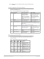
Table 2. Output Formats for DIP Switch 2,3, 4, & 5 Settings
SW2
HD/SD
SW3
1080/720
SW 4
FMT0
SW 5
FMT1
Output
Left Left Left Left 1080i 50/59.94/60
Left Left Left Right 1080PsF
23.98/24/25/29.97/30
Left Left Right Left 1080p 50/59.94/60
Left Left Right Right 1080p
23.98/24/25/29.97/30
Left Right X Left 720p 50/59.94/60
Left Right X Right -
Right X X X 525i/625i

OG-FS-Mini Frame Synchronizer v1.0 18 www.aja.com
Reference Selection DIP Switches
The Reference DIP switch module located on the right is used only for Reference
selection.
Figure 13. Reference Selection DIP Switches
REF SELECT A B
1 Free Run O O
2 Card Ext Ref On O
3 OG Frame Ref 1 O On
4 OG Frame Ref 2 On On
Using the DashBoard Control System
The DashBoard Control System is available as a free download from the openGear
DashBoard Software Download webpage:
http://www.opengear.tv/dashboard-software/#support_box
Ross Video offers comprehensive documentation that covers the extensive
capabilities of the DashBoard Control System:
https://www.rossvideo.com/support/product-documentation/dashboard/
This AJA OG-FS-Mini manual addresses only those essential aspects of the
DashBoard Control System needed to control the OG-FS-Mini card.
Requirements
The DashBoard Control System requires the following components:
• openGear frame with a Frame Controller card
• Ethernet connection betweeen the controlling computer and the openGear
frame
NOTE: The openGear frame ships from AJA with the MFC-8322-S Frame Controller card
for controlling the new AJA DashBoard cards. The openGear frame also supports
the MFC-0G3-N Advanced Networking Frame Controller card, which can be used
to control compatible OG cards.
DashBoard automatically discovers openGear and DashBoard Connect devices,
such as openGear frames and cards that are present and accessible on your
network.
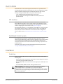
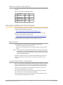
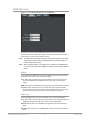
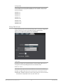
Control Interface Basic Components
The basic components of the DashBoard Control System user interface consist of
the basic tree view of frames and cards, the card information and status panel,
and the parameter controls panel. These elements are shown below in Figure 6.
The basic tree view of frames and cards shows the frames and cards that are
discoverable by DashBoard on your network.
The card information and status panel, shown in the middle panel, display the
basic status of the card currently selected in DashBoard.
The parameter controls panel shows the tabs and parameters that the selected
card has available for configuration and control.

OG-FS-Mini Frame Synchronizer v1.0 19 www.aja.com
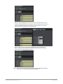
Figure 14. Main Sections of the DashBoard User Interface
Parameter
Controls
Card Information
and Status
Basic Tree View of
Frames and Cards
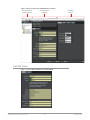
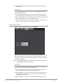
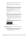
Card Tab Screen
Figure 15. OG-FS-Mini Card Tab Screen in DashBoard

OG-FS-Mini Frame Synchronizer v1.0 20 www.aja.com
The Card tab screen indicates the basic information about the card itself such as
the card name, hardware status, control (local or remote), serial number, software
version and other items.
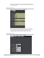
Status Tab Screen
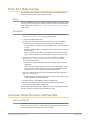
Figure 16. OG-FS-Mini Status Tab Screen in DashBoard
The Status tab screen indicates various signal state alarms, such as OK (green),
warning (yellow) or Not Locked (red). Additionally, for configuration parameters
that are set to "Auto" from the Video, HDMI and Audio tab screens, the
corresponding fields on the Status tab screen report their current setting.
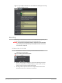
Video Tab Screen
Figure 17. OG-FS-Mini Video Tab Screen in DashBoard
La pagina si sta caricando...
La pagina si sta caricando...
La pagina si sta caricando...
La pagina si sta caricando...
La pagina si sta caricando...
La pagina si sta caricando...
La pagina si sta caricando...
La pagina si sta caricando...
La pagina si sta caricando...
La pagina si sta caricando...
La pagina si sta caricando...
La pagina si sta caricando...
La pagina si sta caricando...
La pagina si sta caricando...
La pagina si sta caricando...
La pagina si sta caricando...
La pagina si sta caricando...
La pagina si sta caricando...
La pagina si sta caricando...
La pagina si sta caricando...
La pagina si sta caricando...
La pagina si sta caricando...
La pagina si sta caricando...
La pagina si sta caricando...
-
 1
1
-
 2
2
-
 3
3
-
 4
4
-
 5
5
-
 6
6
-
 7
7
-
 8
8
-
 9
9
-
 10
10
-
 11
11
-
 12
12
-
 13
13
-
 14
14
-
 15
15
-
 16
16
-
 17
17
-
 18
18
-
 19
19
-
 20
20
-
 21
21
-
 22
22
-
 23
23
-
 24
24
-
 25
25
-
 26
26
-
 27
27
-
 28
28
-
 29
29
-
 30
30
-
 31
31
-
 32
32
-
 33
33
-
 34
34
-
 35
35
-
 36
36
-
 37
37
-
 38
38
-
 39
39
-
 40
40
-
 41
41
-
 42
42
-
 43
43
-
 44
44


AJA OG-FS-Mini Installation and Operation Guide
- Categoria
- Apparecchiature musicali supplementari
- Tipo
- Installation and Operation Guide
in altre lingue
- English: AJA OG-FS-Mini
- français: AJA OG-FS-Mini
- Deutsch: AJA OG-FS-Mini
- português: AJA OG-FS-Mini
Documenti correlati
-
AJA OG-ROI-DVI Manuale utente
-
-
-
AJA OG-X-FR Manuale utente
-
-
-
-
AJA HD10MD4 Manuale utente
-
-
Altri documenti
-
ATEN VC840-AT-U Technical Manual
-
-
WECO 14K3 RACK HV XP Manuale del proprietario
-
-
-
-
-
-