FireClass FC510 FC520 Addressable Fire Alarm Control Panel Manuale utente
- Categoria
- Antincendio
- Tipo
- Manuale utente

FireClass 500
www.fireclass.net
FIRECLASS
Addressable Fire
Control Panels
Installer Manual

This Fire Control panel can be programmed only using
the Software FireClass500 Console release 2.0 or hi-
gher.
Control panel FW ver. 2.0 or higher.
TYCO shall not assume the responsibility for damage ari-
sing from improper application or use. This Fire Control
panel has been designed and manufactured to the hi-
ghest standards of quality and performance.
Installation of this Control panel must be carried out
strictly in accordance with the instructions described in
this manual, and in compliance with the local laws and
bylaws in force
The FC510 and FC520 Fire Control panels comply with
the essential requirements of standards EN54-2;
EN54-4.
Recycling information
The manufacter recommends that customers dispose of their used equip-
ments (panels, detectors, sirens, and other devices) in an environmentally
sound manner. Potential methods include reuse of parts or whole pro-
ducts and recycling of products, components, and/or materials.
Waste Electrical and Electronic Equipment (WEEE) Di-
rective
In the European Union, this label indicates that this product
should NOT be disposed of with household waste. It should be depo-
sited at an appropriate facility to enable recovery and recycling.
NOTE- The series FC500 Fire control panel can support several ad-
dressable devices (Detectors, Modules, Manual call Points, etc). The
present manual includes the instructions for their programming, but
for further informations on those devices and their accessories, plea-
se visits: www.fireclass.net.
The manufacter reserves the right to change the techni-
cal specifications of these products without prior notice.
0051
Tyco Fire & Security GmbH
Victor von Bruns-Strasse 21
8212 Neuhausen am Rheinfall
Switzerland
09
DoP-2015-4178 (FC500PSTN in FC510/FC520)
EN 54-21
Alarm transmission and fault warning routing equipment for fire alarm
systems installed in buildings.
EN 54-21 ESSENTIAL CHARACTERISTICS
Performance of transmission Passed
Operational reliability Passed
Durability of operational reliability, Temperature resistance Passed
Durability of operational reliability, Vibration resistance Passed
Durability of operational reliability, Electrical stability Passed
Durability of operational reliability, humidity resistance Passed
0051
Tyco Fire & Security GmbH
Victor von Bruns-Strasse 21
8212 Neuhausen am Rheinfall
Switzerland
09
DoP-2015-4212 (FC510)
DoP-2015-4213 (FC520)
EN 54-2:1997+A1:2006 EN54-4: 1997+A1:2002+A2:2006
Control and indicating equipment with integrated power supply
equipment for fire detection and fire alarm systems for buildings.
EXPECTED OPTIONS
Fault signals from points
Dependencies on more than one alarm signal: type A and B
Delays to outputs
Disablement of addressable point
Test condition
Output to fire alarm device
EN 54-2 ESSENTIAL CHARACTERISTICS
Performance under fire conditions Passed
Response delay (response time to fire) Passed
Operational reliability Passed
Durability of operational reliability, Temperature resistance Passed
Durability of operational reliability, Vibration resistance Passed
Durability of operational reliability, Electrical stability Passed
Durability of operational reliability, humidity resistance Passed
EN 54-4 ESSENTIAL CHARACTERISTICS
Performance of power supply Passed
Operational reliability Passed
Durability of operational reliability, Temperature resistance Passed
Durability of operational reliability, Vibration resistance Passed
Durability of operational reliability, Electrical stability Passed
Durability of operational reliability, humidity resistance Passed
0051
Tyco Fire & Security GmbH
Victor von Bruns-Strasse 21
8212 Neuhausen am Rheinfall
Switzerland
12
DoP-2015- 4179 (FC500IP in FC510/FC520)
EN 54-21
Alarm transmission and fault warning routing equipment for fire alarm
systems installed in buildings.
EN 54-21 ESSENTIAL CHARACTERISTICS
Performance of transmission Passed
Operational reliability Passed
Durability of operational reliability, Temperature resistance Passed
Durability of operational reliability, Vibration resistance Passed
Durability of operational reliability, Electrical stability Passed
Durability of operational reliability, humidity resistance Passed
The Declaration of Performance (DoP) can be found on
the product webpage at: www.fireclass.net.

TABLE of CONTENTS
INTRODUCTION 5
FC500 Fire Contro Panel 5
Accessory Items 5
Description 5
Input 5
Outputs 5
Operating Features 6
Interface 8
Access to Signalling and Commands 8
Power Supply 8
PARTS IDENTIFICATION 9
The status LED 9
Description of Parts 14
LEDs and KEYs Labels 17
Description of the Control keys 18
INSTALLATION 19
Installing accessory boards 19
Installing the Control panel 19
Installing FC500REP Repeaters 19
Installing the FC500PS e FC500IP board 19
Installing the FC500 Slave control panel 19
Description of the Terminals 20
Main Board terminals 20
The System Wiring 21
Connecting Addressable Analogue Devices 21
Connecting Conventional Devices 22
Connecting Repeater and Slave Control panel
23
Connecting Output Devices 23
Bell Outputs 23
Connecting a Power Supply 24
Thermal Probe 25
Installing the 38Ah battery metal Box 27
Maintenance 27
PC PROGRAMMING 29
Introduction 29
Installation 29
Select language 29
Software window Look 29
Control panel connections 29
Main window 29
Icons description 30
File 30
Communication 31
Options 31
Database 31
Mode setup 31
Help 31
Devices programming 31
Description of the icons in the tool bar. 31
Parameters detectors programming 32
Input modules programming 33
Output modules programming 33
Multiple Input-Output Module - Programming
Parameters (FC410MIO) 33
Manual Call Point programming parameters 34
Zones programming 34
Outputs Programming 34
NAC1, NAC2 and NAC3 Outputs 34
OS1....OS8 Outputs 35
O9....O16 Outputs 35
General Options programming 35
PSTN interface 36
IP interface 37
CLOCK 37
LOG 37
Battery Calculation 37
Loop Wiring calculation 37
User mode 40

PROGRAMMING FROM THE PANEL 41
Using the system 41
L1=First Level: this level allows the Reading
Parameters ONLY: 41
L2= Second Level or USER Level: access to this
level requires entry of the USER PIN (Access Level
2).41
L3=Third Level or INSTALLER Level: access to
this level requires entry of the INSTALLER PIN
(Access Level 3).41
Operating the system 41
Main Page - Accessing the system 42
Insert password 43
Programming Page 44
1 KEY- Auto Enrolling (Autolearning 44
Warning Enrolling (Autolearning) 44
0 KEY - insert-Modify password 45
9 KEY- Restore Default 46
KEY 2 -Device 46
KEY 3- SW zone 47
Detector alarm verification (Smoke delay) 47
4 KEY- OUTPUT 48
Choose Output 48
NAC active on disablements 48
5 Key- Network 49
FC500-MFI programming Procedure 49
KEY 6-TELECOM 50
KEY 7-OPTIONS 50
KEY 8-SYSTEM 51
FC500REP Repeater Address
from the Repeater panel ONLY 51
NETWORK Configuration 51
QUICK START-UP PROCEDURE 52
PROCEDURE 52
Detectors 52
Modules 52
Zones 53
Panel outputs 53
Conventional zone 53
Panel general option 53
ACCESSORY 54
FC500IP - IP Module 54
FC500PSTN - Telecom Module 54
4B - Universal Base 54
FC400H or FC460H - Addressable Heat Detector 54
FC400P or FC460P - Addressable Optical
Smoke 54
FC400PH or FC460PH - Addressable Optical
Smoke & Heat Detector 54
FC410LI - Line Isolator Module 55
FC410MIM - Mini Input Module 55
FC410MIO - Small Addressable Multi I/0 Module 55
FC410SIO - Single Input/Output Module 55
FC420CP - Addressable Break Glass Callpoint
(indoor) 55
FC421CP - Addressable Break Glass Callpoint
(outdoor) 55
FC430SAB/SAM - Sounder Base Address
Modules 55
FC430SB - Loop Low Power Sounder Base 55
4B-I - Isolator Base 56
FC490ST - Loop Service Tool 56
FC410BDM - Beam Detector Module 56
FC410CIM - Contact Input Module 56
FC410DIM - Detector Input Module 56
FC410RIM - Relay Interface Module 56
FC400CH - Addressable Carbon Monoxide + Heat
Detector 56
801RIL - Remote LED Indicator 56
801HL - Remote LED Indicator 56
HVR800-High Voltage Relay 56
MP69-Duct Probe Unit 57
FIRERAY 50-Optical Beam Smoke Detector 57
FC410LPSY and FC410LPAV loop powered
sounders and sounder-beacons 57
FC430LPSB and FC430LPASB Loop Powered
Addressable Sounder/Beacon Base 57
FC410SNM Sounder Notification Module 57
FC410TSM – door control module 57
FC410DDM – Universal fire and gas detector
module 57
FC410QIO Quad input output module 58
FC410QRM Quad relay module 58
FC410LPBS-R/W loop powered sounders and
sounder-beacons (EN54-23) 58
FC430LPBSB Loop Powered Addressable
Sounder/Beacon Base (EN54-23) 58
QUICK GUIDE 59
Technical features 59
Description of the terminals 59

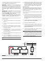
INTRODUCTION
FC500 Fire Contro Panel
In this manual we will use the term FC500 control panel
to indicate the common features of Fire control panel.
Otherwise we will use the specific terms.
FC500 Fire control panel is avalaible in the following
models:
ØFC510 - Analogue addressable Fire Control Panel
with one not expandable Loop and with Switching
Power supply 5,5 A;
ØFC520 - Analogue addressable Fire Control Panel
with two not expandable Loops and with Switching
Power supply 5,5 A;
+The components of these Control panels operate
as intended when the external ambient conditions
comply with the requirements of class EN
60721-3-3:1995.
The Loops of FC500 control panel provide the follo-
wing features:
Ømax 250 analogue devices.
ØThe conventional line of the FC500 contro Panel can
support up to 30 devices.
In any case, FC500 Fire control panel cannot sup-
port more than 2000 devices (500 devices for every
couple of Loop) (up to 2000 m (Loop) with shielded
cable 2x2.5).
The FC500 control panel must be powered by
BAQ140T24 (27,6 V - 5,5 A ) switching power supply.
Moreover all FC500 models provide housing for an LCD
module with 40 characters for line and 4 lines backlit,
which provides written information regarding the
system status and for programming the control panel.
nAccessory Items
FC500REP This Repeater panel is intended for con-
nection (via 4 wires) to FC500 Control panels. It provi-
des all the visual and audible warnings generated by
the Control panel and allows end-users to manage the
system from a remote location (up to 1000 m, with dou-
ble twist shielded cable).
The FC500 "Master" Control panels can support up to
(8) eight FC500REP Repeater panels.
FC500 Slave The FC500 "Master" Control panels can
support up to (7) seven FC500 Slave Control panels.
These Control Panels can be used to expand the
FC500 system, in modular way.
Software FireClass500 Console This user-friendly
software application (Windows) offers a quick and easy
way to program the Control panel and provides event
log functions.
Description
nInput
250 devices max every Loop
30 devices max on the conventional line
nOutputs
This section describes how the Control panel outputs
operate.
Supervised outputs The Control panel will be able to
detect and signal short-circuits and power supply inter-
ruptions on this type of output.
Bypassable(Disabled) outputs The user will be able
to disable (by means of the respective key) this type of
output.
Silenceable outputs The user will be able to stop (via
the Silence key) this type of output.
The outputs can be silenced for an indefinite period (du-
ring Day Mode), or for the programmed Silence Time
(during Night Mode).
INTRODUCTION 5

nOperating Features
Warning The FC500 control panel can be program-
med to provide WARNINGS or PREALARMS status be-
fore ALARM status.
This status will be signalled by the WARNING display.
The panel will generate a warning when an input point
(detector) exceeds its warning threshold and there is
risk of an alarm.
-WARNING STATUS will be signalled by:
Øa screen on LCD display
Øthe WARNING output points if the Pre-alarm option
is enabled;
Pre-alarm If a zone generates an alarm during Day
Mode, the Control panel will start the Pre-alarm Time.
This status will be signalled by:
Øaslow intermittent beep;
Øglowing on the Pre-al. LED;
Øa screen on LCD display
ØActivation of respective outputs , if the Pre-alarm
option is enabled;
+This Control panel will generate an Instant Alarm if
alarm conditions are detected during Night Mode
or if an alarm is triggered from a Callpoint.
During Pre-alarm status, you will be able to:
Øactivate an Evacuation Alarm by pressing and hol-
ding the Evacuate Key (Access Level 1 — refer to
“Access to signalling and commands”),
Østop the Silenceable outputs and interrupt the
Pre-alarm Time by pressing the Silence key
(Access Level 2).
During Silence status (Silence LED glowing), it is pos-
sible to use the Silence key to release the Silenceable
outputs, or use the Reset key to restore standby status.
+If the Control panel is operating in Night Mode, the
Control panel will exit Silence status automatically
when the programmed Night mode Silence time
expires.
Alarm The Control panel will generate an alarm when
the Pre-Alarm Time expires. Alarm status will be signalled
by:
Øafast intermittent beep;
Øglowing on the Alarm LEDs;
Øa screen on LCD display;
Øactivation of the NAC FIRE output;
Øactivation of the FIRE outputs;
Øactivation of other programmed outputs
During Alarm status, PIN Code users (Access Level 2 —
refer to “Access to signalling and commands”) will be
able to:
Østop the Silenceable outputs by pressing the Silence key.
During Silence status (Silence LED glowing), it is pos-
sible to use the Silence key to release the Silenceable
outputs, and the Reset key to restore standby status.
+If the Control panel is in Night Mode (Day Mode
LED OFF), the Control panel will exit Silence sta-
tus when the programmed Night mode Silence
time expires
Day/Night Mode The control panel can operate in
DAY or NIGHT Mode. See "PC PROGRAMMING"
chapter.
If the system is silenced during DAY Mode, SILENCE
status will be held until the system is unsilenced (i.e. un-
less new alarms). If the system is silenced during
NIGHT Mode, SILENCE status will be held until the
Night Mode Silence time expires.
On power up (at default) the system will set to DAY
Mode. During this operating mode, silenced alarms/fa-
ults will not be unsilenced automatically until the Night
Mode Silence time expires.
Fault This Control panel can detect and signal the
Faults shown in the Table n.1:
Fault conditions will be signalled by:
Øaslow intermittent beep (at 1 second intervals);
Øglowing on the Fault LED and on relative Fault LED;
Øa screen on LCD display;
Øactivation of the Fault output;
Øactivation of other programmed outputs;
Øslow blinking on the Fault LED.
The Fault output and other outputs (if duly program-
med by your Installer) will restore to standby automati-
cally when fault conditions clear.
Under certain circumstances, fault conditions may clear
spontaneously, if this occurs, the event will be stored in
the memory until the Control panel Resets.
Stored Fault events will be signalled by:
Øslow blinking on the Fault LED.
6 Addressable Fire Control Panels FC500

Silence This Control panel provides a Silence key
which can be used to restore the Silenceable outputs to
standby status.
Silence status will be signalled by:
Øglowing on the Silence LED.
Silence status will be held until the Silence key is pres-
sed again or, if the Control panel is operating in Night
Mode, until the programmed Night mode Silence time
expires, or until a new Alarm condition is detected.
+Only when the control panel is at Level 2 or at Le-
vel 3 can SILENCE the Silenceable outputs.
INTRODUCTION 7
Switching 1 Switching 1Fault
Switching 2 Switching 2 Fault
Mains fault The Control panel is NOT
powered from the Mains
Battery The Control panel batteries
charger not working properly
Low battery The Control panel batteries are
empty
Earth Leakage to Earth
24A Output 24A Output is shorted
24R Output 24R Output is shorted
Conv. zone open Conventional zone (LC terminal )
open
Conv. zone short Conventional zone (LC terminal)
is shorted
Flash writing Flash writing error
Flash erasing LOG erasing error
Main controller Main controller fault
Firmware main contr. Checksun fault
Prog.data main cont Data programming Checksun
fault
Firmware Display Display Checksun fault
Loop Communication Communication Loop fault
controller
Loop return open Loop negative signal open
Loop signal open Loop positive signal open
Loop local short Local short on Loop controller
Loop right short Right side Loop short
Loop left short Left side Loop short
Non answer Loop device does'nt answer
Dirty level (Smoke detector ONLY) the dirty
threshold has been exceeded
Short circuit Short circuit on Input module
Open circuit Open circuit on Input module
Power supply Main fault
Wrong value A Loop device has a wrong value
Stuck output An Output module relais is not
switched
Same address Loop several devices have the
same address
Display communic. Communication fault on Display
controller
LOG Full LOG fault
LOG not valid LOG contents not valid
OS1 Open OS1 terminal (Supervised output)
open
OS2 Open "
OS3 Open "
OS4 open "
OS5 open "
OS6 open "
OS7 open "
OS8 open "
OS1 short OS1 terminal is shorted
OS2 short "
Table 1 Faults table (Continued..)
OS3 short "
OS4 short "
OS5 short "
OS6 short "
OS7 short "
OS8 short "
TRANSISTOR OS1 OS1 Transistor fault
TRANSISTOR OS2 "
TRANSISTOR OS3 "
TRANSISTOR OS4 "
TRANSISTOR OS5 "
TRANSISTOR OS6 "
TRANSISTOR OS7 "
TRANSISTOR OS8 "
NAC FIRE short NAC Fire terminal is shorted
NAC 1 short "
NAC 2 short "
NAC 3 short "
NAC FIRE open NAC FIRE terminal is open
NAC 1open NAC1 terminal is open
NAC 2open "
NAC 3open "
Transistor NAC FIRE NAC FIRE transistor fault
Transistor NAC 1 NAC 1 transistor fault
Transistor NAC 2 "
Transistor NAC 3 "
Device not
programmed
Device on the loop without
address
Incorrect type Device on the loop different from the
one programmed in the control unit
Noisy loop
The devices on the loop are not
communicating correctly with the control
unit (check the quality of the wiring)
Control unit transm. A 485 control unit is not
responding
Repeater transm,. A 485 repeater is not responding
Control panel Fault A 485 control panel has a fault
Prog. data Controller An error has been detected in the
Controller programming Data
Table 1 Faults Table

Disabled This Control panel can disable:
the devices on the Loop (input and Output devices),
the bell outputs, the software zones;
the network devices (Repeaters or Slave control pa-
nels).
DISABLED zones cannot generate alarms or warnings
of any kind, and DISABLED outputs cannot be activa-
ted.
Disabled status will be signalled by:
Øglowing on the Disabled LED;
+Only when the control panel is at Level 2 or at Le-
vel 3 can DISABLE zones and/or outputs.
Reset Resetting the Control panel will restore the out-
puts to standby status, clear the memory, and interrupt
the power supply to terminals 24R.
+Only when the control panel is at Level 2 or at Le-
vel 3 can Reset the system.
nInterface
Visual Signalling The system status will be signalled
on the Control panel LEDs as follows:
GREEN indicates normal operating conditions;
AMBER indicates specific operating modes (for exam-
ple Day or Night mode), and/or Fault conditions;
RED indicates Alarm conditions.
Memory The Control panel will signal Fault events
(FAULT LED blinking) until the system Resets, even if
the event clears in the meantime.
Audible Signalling The Buzzer will signal the Control
panel status as follows:
Test LAMP-BUZZ-TEST key will allow ALL users to test
the Control panel Buzzer and LEDs.
nAccess to Signalling and Commands
There are 4 access levels, in compliance with the Fire
Safety Regulations in force.
Access Level1 (L1) Viewing: ALL persons can view
the Control panel status (No password requested).
Access Level 2 (L2) Operating the system (PIN Code
entered): PIN Code Users can operate the system.
(User level)
Access Level 3 (L3) Programming and Opening the
Control panel (PIN Code entered): ONLY Qualified
persons with authorization are allowed to open the
Control panel door (requires removal of the screws) for
maintenance purposes or replace batteries. (Installer
Level).
Access Level 4 Repairing or replacing the PCB:
ONLY the Manufacturer should be allowed to repair or
replace the PCB, (requires removal of the screws).
nPower Supply
The power supply system of the FC500 Control panels
complies with EN54-4.
All models are powered by the Mains (110/230 V~,
60/50 Hz):
Øthe FC510 model has Switching Power Supply which
supplies up to 5.5 A at 27.6 V;
Øthe FC520 model has Switching Power Supply which
supplies up to 5.5 A at 27.6 V;
All models can house two 12 V batteries which, when
connected in series, will supply 24 V to the Control pa-
nel and peripherals in the event of black-out, and will
also provide any pickup currents which exceed the ma-
ximum current supplied by the Switching Power Supply.
The FC510 and FC520 model can house two 12V 17 Ah
batteries (YUASA NP 17-12 FR model or similar — flame
class UL94-V2 or higher).
+If necessary, (Full configured Loop or for particular
requirements of the system) FC510 or FC520 con-
trol panel model can be connected to two 12V
38 Ah batteries in an external metal box (see Figu-
re 16).
This Control panel can detect, signal and store in memory
the following power faults: shorted 24V or 24R outputs;
Low battery, Battery fault or Battery disconnected (Low
Battery LED and No Battery LED), Ground fault (Earth
LED) and Mains failure (Mains LED).
+The “No Battery or Low Battery” fault may be si-
gnalled with a delay up to 1 minute. The “Mains”
(Amber) fault will be signalled when the program-
med delay expires.
8 Addressable Fire Control Panels FC500
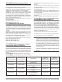
Status Sound Pause Description
Warning 2 s 2 s Slow Intermittent Beep
Prealarm 0,5 s 0,5 s Intermittent beep
Alarm 0,2 s 0,2 s Fast Intermittent Beep
Fault 1 s 1 s Slow Intermittent Beep
Reset no sounds
Test no sounds
Table 2 Buzzer signalling

PARTS IDENTIFICATION
The status LED
The following section describes how the Control panel
LEDs operate. During standby status, ONLY the
GREEN Mains LED and the Day mode LED (if the con-
trol panel is in Day mode) should be On (glowing) .
+ONLY the two FAULT LEDs slow blinking indi-
cate a FAULT event in memory.
PARTS IDENTIFICATION 9
LEDs DESCRIPTION
FIRE Glowing indicates Alarm status. In the event of an Alarm, the Control panel will activate the
unbypassed alarm outputs.
More Alarms Glowing indicates more Alarm status.
Pre-alarms Blinking indicates Pre-alarm status.
Communicator
(Red)
Glowing indicates that transmission was successful.
Blinking indicates that transmission is in progress.
On display of control panel it is possible to know the connection type: PSTN, GSM, or LAN network.
FAULT Glowing indicates the presence of a Fault: the following LEDs or the screen on the display indicate
the type of the Fault. Slow blinking indicates a fault event in memory (Reset turns OFF ).
Logic Unit Glowing indicates a blocked Control panel. IMPORTANT: Maintenance required.
NOTE – When the Control panel is switched on for the first time, this LED will blink until a Reset has
been performed.
Lost Device Glowing indicates that a Loop device has disappeared (missing address).
Communicator
(Amber)
Glowing indicates the Dialer has been disabled; Slow blinking indicates that the dialer has broken
down
Nac Fire
Output
Glowing indicates that NAC FIRE Output is bypassable (disabled), Slow blinking indicates the
presence of a Fault on NAC FIRE Output.
Earth Glowing indicates a Voltage leakage to Earth.
IMPORTANT: Check wiring insulation
Low Battery Glowing indicates Batteries empty or faulty. If this condition persists, the batteries will be unable to
function as intended in the event of blackout, IMPORTANT: New batteries required.
NO Battery Glowing indicates Batteries empty or disconnected ; check if the connections are correct.
MAINS
(amber)
Glowing indicates Mains failure or Switching Power supply fault. During this condition, the Con-
trol panel will be powered by the batteries.
Day mode Glowing indicates that the Control panel is operating in Day Mode
OFF indicates that the Control panel is operating in Night Mode
Disabled Glowing indicates the Disabled status of any bypassable entity.
Silence Glowing indicates that Silenceable outputs have been forced to standby by means of SILENCE key;
in Day Mode the SILENCE will remain until the SILENCE key will not been pressed again,
while in Night Mode after the Silence Time expires automatically the SILENCE will end.
Test Glowing indicates Test conditions on at least one zone.
MAINS
(Green)
OFF indicates Mains failure.
IMPORTANT: Power must be restored before the batteries empty.
Table 3 Description of the status LEDs

ESC
ABC DEF GHI
JKL MNO PQR
STU VWX YZ
1
4
7
2
5
8
0
3
6
9
ESC
F1
F2
F3
F4
MIC
FC500
LAMP
BUZZ
TEST
SILENCE
INVESTIGATE
SILENCE
BUZZER
RESET
EVACUATE
MORE ALARMS
LOGIC UNIT
PRE-ALARM
LOST DEVICE
COMMUNICATOR
DAY MODE
NAC FIRE OUTPUT
DISABLED HEARTH
SILENCE LOW BATTERY
TEST NO BATTERY
MAINS
FIRE
FAULT
COMMUNICATOR
MAINS
1
4
a)
3
5
1
1
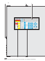
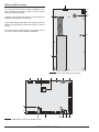
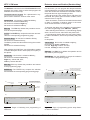
Figure 1 Front view of the FC510, FC520 control panel (a), and of Repeater FC500REP (b)

ESC
ABC DEF GHI
JKL MNO PQR
STU VWX YZ
1
4
7
2
5
8
0
3
6
9
ESC
F1
F2
F3
F4
MIC
FC500
LAMP
BUZZ
TEST
SILENCE
INVESTIGATE
SILENCE
BUZZER
RESET
EVACUATE
MORE ALARMS
LOGIC UNIT
PRE-ALARM
LOST DEVICE
COMMUNICATOR
DAY MODE
NAC FIRE OUTPUT
DISABLED HEARTH
SILENCE LOW BATTERY
TEST NO BATTERY
MAINS
FIRE
FAULT
COMMUNICATOR
MAINS
21
2
b)
2 2
21
2
35
14
1
1
3
PARTS IDENTIFICATION 11

+
-
RS485
24V
7
8910
623
7 7
7 7 7 714 13
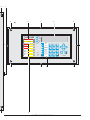
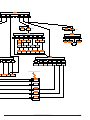
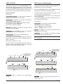
Figure 2 Configuration of the FC510, FC520 control panel.

AC/NFG
+VGND
B+
L
B–
GND
+V
AC/L
F10A/25ØV
LEFT
+
-
RS485
24V
+L2- +L2- +L1- +L1-
RIGHT LEFT RIGHT LC
24A
AUX
24R
AUX-RES
NC
FIRE
NO CNC
FAULT
NO C+
BAT2
-
+
BAT1
-
PS1 PS2
OS1
OS2
OS3
OS4
OS5
OS6
OS7
OS8 O9
O10
O11
O12 O13
O14
O15
O16
+
NAC
-
FIRE
+
-
NAC1
+
-
NAC2
+
-
NAC3 12V
-
SP
LE LI
17
012 15 12
19
21
22
20 12
12 21
11
20 18
16
24 25 2626a 26b
PARTS IDENTIFICATION 13

Description of Parts
This section describes the components of the FC500
serie Control panels, and FC500REP Repeater.
Unless otherwise stated, the numbers in boldface in this
Manual refer to the Tables ands Diagrams in this sec-
tion.
The parts identification numbers in the diagrams go cloc-
kwise.
P. Description
1Surface Cable conduit entry
2Door screws
3LED label slots
4KEYs label slots
5Display
6User interface board
7Nuts to secure the User interface board on the
cover of Control Panel or Repeater
7a Earth connection (see figure 3)
P. Description
8Flat cable: for the Display module board con-
nection with User interface board
9Jack for the connection between display mo-
dule and User interface board
10 Flat cable: for the User interface board con-
nection with Main board
11 Jumper to Default programming (Future use)
(Default //)
12 Anchor screw locations
13 Signalling LEDs Label
14 Identification Keys Label
15 Main Board
16 Switching power supply support
17 Switching power supply screw
18 Switching power supply
19 Anchor for power supply wires
20 Batteries (NOT supplied):
FC510, FC520 = 2 da 12 V 17 Ah
(Accessory item: 2 da 12V 38 Ah -see figure 16-
21 Chased cable conduit entry
22 Thermal probe
14 Addressable Fire Control Panels FC500
2a)
2 2
2
1
623
+
-
RS485 24V
7 7 7
7 7 7 7a
14 13
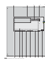
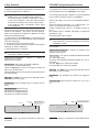
Figure 3 Configuration of the FC500REP Repeater a) frontplate (inside view); b) backplate.

P. Description
23 Jack for the connection between the User interfa-
ce to Repeater (RS485 interface accessory item)
24 FC500PS Telecom Module
25 Loudspeaker
26 FC500IP board
P. Description
26a Connection FC500IP with PCLINK cable,see
note*(2)
26b Power FC500IP,see note*(2)
PARTS IDENTIFICATION 15
1
11
b)
12 12
12 12
21
1
Repeater PCB
Nut M3
Support
Earth connection
Repeater Cover
Plastic Frame
Washer
Repeater earth connection (nut 7a)
O13
O14
O15
O16
+
NAC
-
FIRE
+
-
NAC1
+
-
NAC2
+
-
NAC3 12V
2626c
Figure 4 FC500IP board connection with the motherboard via the flat cable.

16 Addressable Fire Control Panels FC500
26c Connection FC500IP with Flat cable, see
note*(2)
27 Mains indicator LED (switching power supply)
28 Switching-power-supply anchor hole
29 Switching-power-supply output voltage con-
trol input (connected at factory)
30 Fine trimmer for the Switching-power-supply
output Voltage
31 Auxiliary power-supply terminals (27.6 V)
32 Mains power terminals (110/230V~ 60/50 Hz)
33 Switching-power-supply screws
34 Switching-power-supply fuse — protects aga-
inst overload:
BAQ140T24 = F 4A 250V
35 Cable: connects the Switching power supply
to the Main board (connected at factory)
35a Voltage switch (110V or 230V)
36 Switching-power-supply anchor
37 Switching-power-supply closure rivet
38 Jack for the User interface board
39 Microprocessor
40 RS232 Serial Port
41 Terminal board
42 Terminal board
43 Jack for the thermal probe
44 Jack for the BAQ140T24 Switching power
supply
45 Battery output voltage control panel (connec-
ted at factory)
46 RS485 terminal board
47 Jack for Extinguishment Module (Future use)
48 Jack (Future use)
49 Jack (Future use)
50 Jumper for Earth Fault (Leakage to Earth)
signalling (Default // ) *(1)
51 Microphone
52 Jack for the connection between User Interfa-
ce board and the Main board
53 Buzzer
54 Control Panel Backplate
55 38Ah Batteries Backplate
56 Connecting Threaded tube
57 Nuts on Control Panel Backplate
58 Nuts on 38Ah Batteries Backplate
59 12V 38Ah Batteries (accessory item)
(see Figure 16)
*NOTE(1)
Before connecting the Fire control panel to PC for the PC
programming phase, remove the jumper 50 of main bo-
ard.
After the programming phase is finished, replace the
jumper otherwise the Earth fault (Leakage to Earth) will
not be detected.
+*(2) If you connect the FC500 IP board with the mot-
herboard via flat cable (26c) (Fig. 4) the Digital Com-
municator function will be activated. If the Digital
Communicator function only is requested the
PCLINK cable (26a) and the cables for board power
are not necessary (26b) (see Figure 4). If both Digital
Communicator than PC interface functions are re-
quested the flat cable and the PCLINK cable are ne-
cessary, but not the power connection (26b).
!Be sure that the main voltage is the same of the
input voltage set on the BAQ140T24 power
supplier. Move the switch 35a if the BAQ140T24
input voltage is different from the main voltage,
ONLY when the power supplier is not connec-
ted to the main power. Please note that the po-
wer supplier will be damaged if it is connected
to the 230 V main power when it is set for 110 V.
AC/NFG
+VGND
B+
L
B–
GND
+V
AC/L
F4A/25ØV
F10A/25ØV
110V 220V
110/220 is selected by switch.
Before power on please check
Input voltage avoiding damage
Figure 5 BAQ140T24 Switching-power-supply

LEDs and KEYs Labels
To insert the LED and Keys Labels (supplied) in the
User Interface (see Figure 2, parts 13 and 14) work
through the following steps:
1) Remove the screws 2and open the Control panel or
Repeater FC500REP (see Figure 3).
2) Corresponding the Aor B(in the overlay) insert the
relative LED and KEYS Labels (see Figure 1, parts 3
and 4);
3) check the right position (Figure 1) and then secure
the Control panel or the Repeater FC500REP.
PARTS IDENTIFICATION 17
+
-
RS485
24V
5
9
51
53
23
52
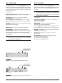
Figure 6 Parts: User interface-LCD board
LEFT
+
-
RS485 24V
+L2- +L2- +L1- +L1-
RIGHT LEFT RIGHT LC 24A
AUX
24R
AUX-RES
NC
FIRE
NO CNC
FAULT
NO C+
BAT2
-
+
BAT1
-
PS1 PS2
OS1
OS2
OS3
OS4
OS5
OS6
OS7
OS8 O9
O10
O11
O12 O13
O14
O15
O16
+
NAC
-
FIRE
+
-
NAC1
+
-
NAC2
+
-
NAC3 12V
38 11 40 41
47
42
46 44 4345 42
39
48
49 50
Figure 7 Identification of the parts: a) Main board .

Description of the Control keys
+Test, Silence Buzzer and Evacuate Control keys
ONLY can be activated without password (access
level L1), all the others Control keys can be activa-
ted with password (access level L2 and L3)
Lamp/Buzz/Test See table 4
Silence See table 4
Investigate See table 4
Silence Buzzer See table 4
Reset RESET will stop Alarm, Prealarm, Warning and
FAULT conditions. Access to this command is limited to
authorized personnel only (installer or user code PINs).
The system will reprocess any alarm, prealarm, war-
ning or fault signal which is not cleared by RESET ope-
rations. Command keys cannot be used when RESET
is running.
The repeaters FC500REP can be RESET by the instal-
ler or user code PINs.
Evacuate See table 4
F1, F2, F3, F4 See table 4
18 Addressable Fire Control Panels FC500
KEY DESCRIPTION
Lamp/Buzz
Test
This key can be used to test the buzzer and LEDs . If this key is pressed (when the Control panel is
functioning as intended), all the LEDs will glow and the buzzer will emit a continuous beep.
Silence This key can be used to restore the Silenceable outputs to standby status. Silence status will be held
until the Silence key is pressed again in Day Mode, or if the Control panel is operating in Night
Mode, until the Night mode Silence time expires or until a new Alarm/Trouble condition is detec-
ted.
Investigate This key can be used to refresh the “PreAlarm Time”: if this key is pressed during “PreAlarm”, the
remaining PreAlarm time will be increased with the programmed "Recognition delay".
Silence
Buzzer
Key to silence the local buzzer of the control panel: the buzzer will be operating every time a new
event will be activated
Reset This key can be used to reset the Fire detectors and restore all outputs to standby status (Supervi-
sed/Silenceable outputs, NON-Supervised/Non-Silenceable outputs and Alarm zone outputs)
Evacuate key to activate the evacuation: if this key is pressed for over 2 seconds, the system will generate an
alarm.
F1, F2, F3, F4 Function keys of the Display; their function will be various according to different screen of display
Table 4 Description of the keys

INSTALLATION
!Installation of this system must be carried out
strictly in accordance with the instructions in
this section, and in compliance with the local
safety regulations in force.
To install the control panel work through the following
steps:
ØChoose suitable mounting locations for the Control
panel, detectors, fire warning and fire control devi-
ces.
ØLay the cables between the Control panel and the
system peripherals.
ØIf necessary, install any accessory modules.
ØBefore mounting the Control panel to the wall, insert
the LED and Keys Labels (supplied) in the Interface
User (see pag.17).
ØCarry out the necessary connections, leaving the po-
wer-supply connection until last.
ØProgram the Control panel in accordance with the in-
structions in the “PROGRAMMING” section.
ØTest the entire system (Control panel, detectors, fire
warning and fire control devices).
+Accessory Modules should be installed before mo-
unting the Control panel to the wall.
Installing accessory boards
!Ensure that the Control panel power supply
(Mains and Batteries) has been disconnected
before installing any accessory Modules.
Installing the Control panel
Work carefully through the following steps (see the Fi-
gures 1, 2 and 3).
1. Remove the screws (2) and open the Control panel.
2. Drill the anchor screw holes.
!Check for water pipes and electrical wiring be-
fore drilling.
3. If necessary, using a hammer or similar tool, remo-
ve the surface conduit wire knockouts 1.
+The cable conduit union with the case must be se-
cured by HB Flame Class (or higher) lock nuts.
4. Pull the wires through the chased wire entry 21 then,
using the anchor screws, secure the backplate to the
wall.
Installing FC500REP Repeaters
Repeaters can be wall mounted, or flush mounted to an
ave®BL08 outlet box (or similar).
Work carefully through the following steps.
1. Lay the connection cables (refer to “Connecting
Repeaters”).
2. Remove the screws 2(see Figure 3) and open the
Repeater FC500REP.
3. If you are flush mounting the Repeater, go to step
5. If you are wall mounting the Repeater, drill the
anchor screw holes 12.
4. Pull the wires through the wire entry 21, then, using
the anchor screws, secure the Repeater to the wall.
5. Complete the connections to the terminal board 23
of the RS485 Interface, as described in the “Con-
necting Repeaters” section.
- Connect the earth wire to the threaded support 7a
on the cover, as illustrated in Figure 3.
6. Set the Repeater Address.
Installing the FC500PS e FC500IP board
Please refer to the dedicated manuals.
Installing the FC500 Slave control panel
See "Installing the Control panel paragraph".
INSTALLATION 19

Description of the Terminals
This section describes the Control panel terminals.
nMain Board terminals
+L1-/LEFT (+)Loop 1-Positive signal, left side.
(-)Loop 1-Negative signal (return), left side.
+L1-/RIGHT (+)Loop 1-Positive signal, right side.
(-)Loop 1-Negative signal (return), right side.
+L2-/LEFT (+)Loop 2-Positive signal, left side.
(-)Loop 2-Negative signal (return), left side.
+L2-/RIGHT (+)Loop 2-Positive signal, right side.
(-)Loop 2-Negative signal (return), right side.
+Each Loop supports 250 (Analogue detectors, Input
modules, Conventional Zone modules, Manual callpo-
ints, Output modules and Sounders). In all the control
panel supports up to 500 devices with 2 Loop.
LC Conventional Input Line -Supervised and
Bypassable (Disabled) — This line supports 30 con-
ventional fire devices (Optic Smoke detectors, Heat de-
tectors, Manual callpoints).
Connect terminal [LC] to ground terminal [ M]) using a
3900 ohm resistor (orange-white-red). A 680 ohm resi-
stance (normal value for Fire detectors) parallel to the
3,900 ohm resistor will activate the programmed actions
and preset times of the Conventional Line outputs and the
Non-supervised output (terminals NC, NO and C).
+The Conventional Line supports 30 Conventional
detectors. ATTENTION: DO NOT connect more
than 500 detectors and/or manual call points to
each main PCB.
[M]Negative.
485 Serial Bus Terminals for FC500REP repeater pa-
nels (maximum 8) and FC500 as Slave panels (maxi-
mum 7). Serial bus terminals [+] and [-]; 27.6 V power
voltage terminals [M] and [24V].
AUX Auxiliary power 24 V (0.5A max) Power supply to
devices that operate at 24 V (powered by the standby
batteries):
ØPositive (27.6 V) on terminal [24A];
ØNegative on terminal [M].
AUX-RES Auxiliary power 24 V (0.5A max). The
system will interrupt power from terminal [24R] during
Reset. Power supply to devices that operate at 24 V
(powered by the standby batteries):
ØPositive (27.6 V) on terminal [24R];
ØNegative on terminal [M].
[NC][NO][C] FIRE Non-supervised fire output. Dry
contact relay for non-supervised devices:
ØDuring standby status —— terminal [C] closes to ter-
minal [NC];
ØIn the event of fire —— terminal [C] closes to terminal
[NO].
[NC][NO][C] FAULT Non-supervised fault output. Dry
contact relay for non-supervised devices:
ØDuring standby status —— terminal [C] closes to ter-
minal [NC];
ØIn the event of fault —— terminal [C] closes to termi-
nal [NO].
+EN54-2 cerification applies ONLY when, FAULT
output is not J (EN 54-1) type, therefore this output
MUST NOT UTILIZED to manage Fault transmis-
sion devices.
+BAT2- Terminals to connect the batteries inside the
FC500 control panel (see Figure2).
+BAT1- Terminal to connect remote batteries or Po-
wer supply.
PS1 BAQ140T24 power supply first connector.
PS2 BAQ140T24 power supply second connector.
OS1...OS8 Programmable, Silenceable, Bypassa-
ble (Disabled), Supervised Outputs.
These are normally-open terminals (open-collector)
which will close to ground, when the connected event
becomes activ, and will remain in this state until the ge-
nerating event has ended (so after a manual reset or a
fault restore.
ØThese outputs can be bypassed via the DISABLE
menu.
Connect an EOL 27.000 ohm resistor between termi-
nals [OS] and [ M] of these outputs. This will allow the
control panel to detect and signal when the outputs are
shorted and/or open.
+NOTE: The EOL resistor must be connected to
the last device on the Supervised output. Connect
a diode (1N4002 or 1N4007) in series to the devi-
ces connected to these outputs.
O9...O16 Programmable, Silenceable, Bypassable
(Disabled) NOT Supervised outputs —— These are
normally-open terminals (open-collector) which close to
ground when the connected event will active. These ter-
minals will remain closed to ground even after the gene-
rating event has ended. These outputs can be forced to
standby (Not programmable polarity) by resetting the
control panel.
20 Addressable Fire Control Panels FC500
La pagina sta caricando ...
La pagina sta caricando ...
La pagina sta caricando ...
La pagina sta caricando ...
La pagina sta caricando ...
La pagina sta caricando ...
La pagina sta caricando ...
La pagina sta caricando ...
La pagina sta caricando ...
La pagina sta caricando ...
La pagina sta caricando ...
La pagina sta caricando ...
La pagina sta caricando ...
La pagina sta caricando ...
La pagina sta caricando ...
La pagina sta caricando ...
La pagina sta caricando ...
La pagina sta caricando ...
La pagina sta caricando ...
La pagina sta caricando ...
La pagina sta caricando ...
La pagina sta caricando ...
La pagina sta caricando ...
La pagina sta caricando ...
La pagina sta caricando ...
La pagina sta caricando ...
La pagina sta caricando ...
La pagina sta caricando ...
La pagina sta caricando ...
La pagina sta caricando ...
La pagina sta caricando ...
La pagina sta caricando ...
La pagina sta caricando ...
La pagina sta caricando ...
La pagina sta caricando ...
La pagina sta caricando ...
La pagina sta caricando ...
La pagina sta caricando ...
La pagina sta caricando ...
La pagina sta caricando ...
-
 1
1
-
 2
2
-
 3
3
-
 4
4
-
 5
5
-
 6
6
-
 7
7
-
 8
8
-
 9
9
-
 10
10
-
 11
11
-
 12
12
-
 13
13
-
 14
14
-
 15
15
-
 16
16
-
 17
17
-
 18
18
-
 19
19
-
 20
20
-
 21
21
-
 22
22
-
 23
23
-
 24
24
-
 25
25
-
 26
26
-
 27
27
-
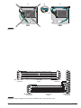 28
28
-
 29
29
-
 30
30
-
 31
31
-
 32
32
-
 33
33
-
 34
34
-
 35
35
-
 36
36
-
 37
37
-
 38
38
-
 39
39
-
 40
40
-
 41
41
-
 42
42
-
 43
43
-
 44
44
-
 45
45
-
 46
46
-
 47
47
-
 48
48
-
 49
49
-
 50
50
-
 51
51
-
 52
52
-
 53
53
-
 54
54
-
 55
55
-
 56
56
-
 57
57
-
 58
58
-
 59
59
-
 60
60


FireClass FC510 FC520 Addressable Fire Alarm Control Panel Manuale utente
- Categoria
- Antincendio
- Tipo
- Manuale utente
in altre lingue
Documenti correlati
Altri documenti
-
EcoFlow 100W Rigid Solar Panel Manuale utente
-
ADEMCO Security System VISTA-15CN Guida d'installazione
-
Pyronix Matrix 832 Guida d'installazione
-
-
Risco ProSYS 128 Manuale utente
-
Pyronix Matrix 832 Manuale utente
-
Azbil MTG11A Manuale utente
-
Crowcon Hydra256 Istruzioni per l'uso
-
Crow RUNNER 8/64 Guida d'installazione
-