GBC Ultra Ultra MP StreamPunch Manuale utente
- Tipo
- Manuale utente

StreamPunchTM Ultra/Ultra MP
GB Operation Instructions Manual
F Manuel d'instructions et d'utilisation
E Manual de instrucciones de operación
I Manuale d’istruzioni
D Bedienungsanleitung
NL Gebruiksaanwijzing
PT Manual de instruções de operação
RU Руководство по эксплуатации
CHI
操作使用手册
Part Number: 7715805
Revision number: F1
Issue Date: October 2018
All manuals and user guides at all-guides.com

StreamPunchTM Ultra/Ultra MP
English 3
Français 13
Español 23
Italiano 33
Deutsch 43
Nederlands 53
Português 63
На русском языке 73
中文 83
GB Please read these instructions carefully and keep them in a safe place for future
reference.
F Lisez attentivement le présent manuel et conservez-le en lieu sûr afin de pouvoir le
consulter en cas de besoin.
E Lea estas instrucciones cuidadosamente y manténgalas en un lugar seguro para consulta
en el futuro.
I Si prega di leggere attentamente le presenti istruzioni d'uso e di conservarle a portata di
mano per ogni ulteriore consultazione.
D Bitte lesen Sie diese Bedienungsanleitung sorgfältig durch und bewahren Sie sie als
Referenz für die Zukunft an einem sicheren Ort auf.
NL Lees deze gebruiksaanwijzing aandachtig door en bewaar deze op een veilige plaats voor
later.
PT Leia atentamente estas instruções e mantenha-as em um lugar seguro para futuras
consultas.
RU Внимательно прочтите все руководство и сохраните его на будущее.
CHI 请仔细阅读本手册,并将其保存在安全位置供日后参考。
All manuals and user guides at all-guides.com

3
GB
StreamPunchTM Ultra/Ultra MP
TABLE OF CONTENTS
1. SAFETY INSTRUCTIONS 3
Important safeguards 3
Cleaning 3
Service 4
Safety messages 4
2. INTRODUCTION 4
3. QUICK START GUIDE 5
4. USER OPERATIONS 6
1. SAFETY INSTRUCTIONS
THE SAFETY OF YOU AND OTHERS IS VERY IMPORTANT TO
GBC. IMPORTANT SAFETY MESSAGES AND INFORMATION ARE
CONTAINED IN THIS MANUAL AS WELL AS ON THE MACHINE
ITSELF. PLEASE MAKE SURE YOU CAREFULLY READ AND
UNDERSTAND ALL OF THESE BEFORE OPERATING THE
MACHINE.
THE SAFETY ALERT SYMBOL PRECEDES EACH SAFETY
MESSAGE IN THIS OPERATION INSTRUCTIONS
MANUAL. THIS SYMBOL INDICATES A POTENTIAL
PERSONAL SAFETY HAZARD THAT COULD HURT YOU
OR OTHERS.
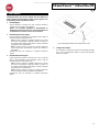
THE FOLLOWING PICTORIAL IS FOUND ON THE STREAMPUNCH
ULTRA:
This safety symbol means that you might get
seriously hurt or killed if you open the product
and expose yourself to hazardous voltage.
NEVER remove the screwed on covers.
ALWAYS refer service requirements to
qualified service personnel.
5. USER DISPLAY 7
6. PROBLEM SOLVING 9
7. SPECIFICATIONS 9
8. DIE SET USER MANUAL 10
Important safeguards
Use the StreamPunch Ultra only for its intended purpose of
punching paper and covers according to the indicated
specifications.
Retain this Operation Instructions manual for future use.
CAUTION: THE PRINTER ON/OFF SWITCH DOES NOT
CUT OFF POWER FROM THE PUNCH.
The StreamPunch Ultra must be connected to a supply voltage
corresponding to the electrical rating of the machine operation
instructions (also listed on the serial number label).
The grounding plug is a safety feature and will only fit into the
proper grounding-type power outlet. If you are unable to insert the
plug into an outlet, contact a qualified electrician to have a suitable
outlet installed.
Do not alter the plug on the end of the cordset (if provided) of the
StreamPunch Ultra. It is provided for your safety.
Unplug the StreamPunch Ultra before moving the machine or
whenever the machine is not in use for an extended period of
time.
Do not operate the StreamPunch Ultra if the machine has a
damaged power supply cord or plug. Do not operate the machine
after any malfunction. Do not operate the machine in case of liquid
spills, or if the machine has been damaged in any other way.
Do not overload electrical outlets beyond their capacity. To do so
may result in fire or electrical shock.
Cleaning
You may clean the exterior of the StreamPunch Ultra using a soft,
damp cloth.
Do not use detergents or solvents as damage to the machine may
occur.
All manuals and user guides at all-guides.com

4
GB
StreamPunchTM Ultra/Ultra MP
Safety messages
MAIN CORDSET SELECTION
(THE FOLLOWING NOTE ONLY APPLIES ONLY TO THE UNITS
RATED 230V 50Hz, AND LOCATED IN THE EUROPEAN UNION)
CAUTION: WHEN CHOOSING A DETACHABLE LINE
CORD FOR USE WITH YOUR STREAMPUNCH ULTRA,
ALWAYS FOLLOW THE FOLLOWING PRECAUTIONS
The cordset consists of three parts: the attachment plug, the cord and
the appliance inlet. Each of these components must have European
regulatory safety approvals.
The following minimum electrical ratings for the specific cordset are
published for safety purposes.
DO NOT USE CORDSETS THAT DO NOT MEET THE FOLLOWING
MINIMUM ELECTRICAL REQUIREMENTS.
PLUG: 3 amperes, 250 volts, 50/60 Hz, Class 1, 3 conductor,
European safety approved.
CORD: Type H05VV-F3G0.75, Harmonized (< HAR >). The “< >”
symbols indicate cord approved according to appropriate European
standard (NOTE: “HAR” may be substituted for approval mark of
European safety agency that approved the cord. An example would be
“< VDE >”).
APPLIANCE CONNECTOR: 3 amperes, 250 volts, 50/60 Hz,
European safety approved, Type IEC 320. The cordset shall not
exceed 3 meters in length. A cordset with component electrical ratings
greater than the minimum specified electrical ratings may be
substituted.
FCC NOTE
(THE FOLLOWING NOTE ONLY APPLIES TO THE UNITS RATED
115V 60Hz.)
This equipment has been tested and found to comply with the limits for
a Class A digital device, pursuant to Part 15 of the FCC Rules. These
limits are designed to provide reasonable protection against harmful
interference when the equipment is operated in a commercial
environment.
This equipment generates, uses, and can radiate radio frequency
energy and, if not installed and used in accordance with the Operation
Manual, may cause harmful interference with radio communications.
Operation of this equipment in a residential area is likely to cause
harmful interference in which case the user will be required to correct
the interference at his/her own expense.
CAN ICES-3 (A)/NMB-3(A)
CAUTION: ANY MODIFICATIONS MADE TO THIS DEVICE
THAT ARE NOT APPROVED BY GBC MAY VOID THE
AUTHOIRITY GRANTED TO THE USER BY THE FCC
AND/OR INDUSTRY CANADA TO OPERATE THIS
EQUIPMENT.
Service, StreamPunch Ultra
Do not attempt to service your StreamPunch Ultra yourself. Contact an
authorized service representative for any required repairs or major
maintenance for your StreamPunch Ultra.
DO NOT REMOVE THE MACHINE’S COVER.
There are NO user-serviceable parts inside the machine in order to
avoid potential personal injury and/or damage to property or the
machine itself.
Service, Diesets
Every dieset is thoroughly oiled at the factory prior to shipping. During
normal use this oil will be exhausted and should be replaced. As part of
regular maintenance, each dieset should be oiled.
See Section 8 StreamPunch Ultra Dieset Manual for instructions on
servicing the Diesets.
2. INTRODUCTION
Thank you for purchasing the StreamPunch Ultra. It is a versatile
production system that will enable you to punch documents for a variety
of binding styles by means of a simple die change. It has also been
designed for easy operation.
The StreamPunch Ultra is an innovative solution for punching paper
and offers the following design features:
Quick-change die sets that can be interchanged without any tools.
All StreamPunch Ultra die sets include an Identification Label
providing the user with the hole pattern and name.
Convenient storage area for two extra Die Sets.
Duty Cycle and Product Positioning
The GBC StreamPunch Ultra provides a flexible, cost effective
punching solution for light to medium level punching production
environments. It is designed for production print users that typically
punch their documents at an average of 20-30% of their overall
workflow. For customers that run continuous punching for long runs of
over 4 hours, performance may vary or degrade due to a wide range of
media weights and environmental conditions that can occur.
AMPV - Nominal 600,000 average monthly print volume (A4/letter),
assuming volume is split 50/50 between punch and bypass (300,000
punch and 300,000 bypass).
Maximum Recommended Monthly Volume - The maximum
recommended monthly punch volume should NOT exceed 400,000.
Maximum Punch Duty Cycle - In addition to the aforementioned
conditions, no more than 2 sheets of 300gsm per 5 sheets of 75gsm
should be punched. The heaviest paper stocks are typically used as
only the front and back covers of the bound book application.
Operating Die Set Supplies
Dies are considered consumables and when worn, must be replaced
since sharpening is not possible.
Each die set has a 90-day warranty from the date of purchase. The
warranty is void if the die is used beyond its specifications.
Punch die life will be maximized if oiled every 100,000 punch cycles
(see Dieset Service for details)
Die sets have an expected use life of 750,000 punches using
20 lb/75 gsm paper. This is a minimum life expectation only. Die life is
NOT guaranteed due to a wide range of media weights and
environmental conditions that the dies may endure. If you are going to
be punching extended runs that exceed the die use life, it is strongly
recommended that you have sufficient numbers of the appropriate die
sets on hand to continue with minimal downtime.
All manuals and user guides at all-guides.com

5
GB
StreamPunchTM Ultra/Ultra MP
3. QUICK START GUIDE
StreamPunch Ultra must be connected to AC power to enable any
feature of the machine. Below are three modes of operation of
StreamPunch Ultra.
1. Bypass Mode:
This operation will allow paper to pass through the StreamPunch
Ultra without being punched.
This is the default mode of operation for StreamPunch Ultra.
Make sure the Punch Icon is not selected in the printer’s User
Interface.
2. Single Punch Mode:
This operation will punch the trail edge of all sheets that pass
through the StreamPunch Ultra.
Step 1: A properly configured die set must be inserted before
running punch mode. See section 4.A for details on Die set
changes and follow the labels on the die set for configuration.
Step 2: Before starting a print job select the Punch (Single
Punch) icon to enable punching.
StreamPunch Ultra will now function in Single Punch mode.
3. Double Punch Mode:
This operation will punch the two rows of holes- One in the middle
of the sheet and the other adjacent to the trail edge of all sheets
that pass through the StreamPunch Ultra.
Step 1: A properly configured die set must be inserted before
running punch mode. See section 4.A for details on Die set
changes and follow the labels on the die set for configuration.
Step 2: Before starting a print job select the Double Punch icon
to enable punching.
StreamPunch Ultra will now function in Double Punch mode.
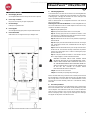
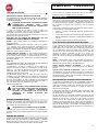
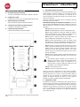
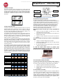
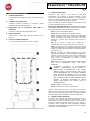
Layout of StreamPunch Ultra LCD User Interface
4. Die Set Configuration
To configure the Die Set for the desired sheet size that is being
processed see section 8 – Die Set User Manual.
UP
DOWN
ENTER/
OK
All manuals and user guides at all-guides.com

6
GB
StreamPunchTM Ultra/Ultra MP
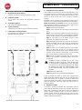
4. USER OPERATIONS
A. Interchanging Die Sets:
Are completed without tools and only take seconds to perform
B. Punch Chip Container:
Easy-to-access chip tray for quick chip disposal
C. Die Set Storage:
Holds up to 2 spare Die Sets
D. Punch Bypass:
Short straight-through paper path for unpunched documents
E. Punch Mode Path:
Wide radius turn can support stocks up to 300g/m2 cover
Paper flow and User Interactive sections of StreamPunch Ultra
A. Interchanging Die Sets:
Your StreamPunch Ultra offers the convenience of interchangeable die
sets, allowing you to economically punch documents for a wide variety
of binding styles. Changing the machine's die sets is both quick and
easy, as the following instructions illustrate:
Note: For advanced Die Set Configuration instructions- See Section 8
Die Set User Manual.
Removing Die Sets from the Machine: The inter-changeable die set
slot of the StreamPunch Ultra is located adjacent to the Punch Chip
container at the bottom of the punch.
Step 1: Stop the printer/copier.
Step 2: Open the StreamPunch Ultra access door panel.
Step 3: Securely grasp the die lock handle and rotate it in the
CCW direction, as indicated in the label near the die lock handle.
This releases the die from the locked position.
Step 4: Slide the die set out until it is fully removed, supporting it
with both hands.
Step 5: Properly store the removed Die Set in the Die Set storage
area. (keep away from dust, dirt, accidental falls from the edge of
counters, etc.).
Step 6: Select the desired Die Set for your new job and slide it into
the Die Set slot. Push the Die set firmly until the Die stop feature
contacts the round magnet. This is critical in ensuring the proper
position of the die set.
Step 7: Grasp the handle and rotate it in CW direction until the
latch is fully engaged, as shown indicated in the label.
WARNING: POSSIBLE PINCH POINT HAZARD. WHEN
INSTALLING DIE SETS IN YOUR STREAMPUNCH ULTRA,
ALWAYS KEEP FINGERS AND OTHER BODY PARTS OUT
OF THE MACHINE’S DIE SET SLOT AND AWAY FROM ALL
AREAS OF THE DIE SET, EXCEPT FOR THE FINGER HOLE
IN THE DIE SET. FAILURE TO FOLLOW THESE
PRECAUTIONS MAY RESULT IN INJURY.
Step 8: Close the Access Door Panel.
Step 9: Proceed with your printing and punching job.
Please note that when using a new die some oil will be present around
the punched holes on the sheet. After punching 25 to 50 sheets the die
will no longer leave oil on the sheets. It is recommended that a short
test print job be run after installing a new die or a die that has recently
been oiled.
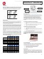
B. Punch Chip Container:
The Punch Chip Container for your StreamPunch Ultra is located at the
front of the machine’s base. The drawer should periodically be pulled
out and emptied. The StreamPunch Ultra uses a sensor to determine
when the punch container is full. Once the punch container becomes
full the LCD display shows "Chip Tray Full" message and a message
also appear on the printers user interface screen.
All manuals and user guides at all-guides.com

7
GB
StreamPunchTM Ultra/Ultra MP
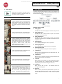
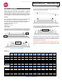
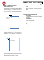
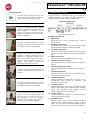
C. Paper Clearing:
When paper is jammed in the paper path of
StreamPunch Ultra the LCD display shows the
area where a sheet(s) is jammed.
Area
Description
If paper is jammed in Zone 1, lift the paper guide
plate located just inside, reach and remove the
jammed paper. To close the paper guide, raise
the handle to unlatch the mechanism and firmly
close it.
If paper is jammed in Zone 2, move the door to
the right, reach in and remove the jammed paper.
If paper is jammed in Zone 3, press the top lever
while holding the bottom lever. This will unlatch the
chute; continue to open the chute until it reached
the magnet on the right side. Reach in and remove
the paper. To return the chute to the closed
position, move it back in the opposite direction until
the latch mechanism is activated.
If paper is jammed in Zone 5, unlatch the chute,
reach in and remove any jammed paper.
If paper is jammed in Zone 6, move the door to
the left, reach in and remove the jammed paper.
Before uninstalling the die set, ensure Zone 3 and
5 are cleared of any jammed paper. If there is no
paper found in Zone 3 and 5, then uninstall the
die set to remove any jammed paper. (see
Section 4. Changing the Interchangable die sets)
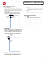
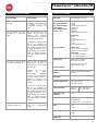
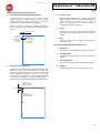
5. USER DISPLAY . OPERATION CONTROLS
Located on the front of the StreamPunch Ultra is a user interactive LCD
panel that provides Messages; Settings and Information relating to the
functions of the punch unit.
LCD Panel Overview
Messages on the LCD Panel
1. Ready Bypass
StreamPunch Ultra is ready to bypass, sheets will not be punched.
2. Ready Single Punch
StreamPunch Ultra is ready to process a punch job, all sheets
through the unit will be punched.
3. Ready Double Punch
StreamPunch Ultra is ready to process a punch job, all sheets
through the unit will be punch in the middle of sheet and along trail
edge of the sheet.
4. Running Bypass
This is displayed when Bypass mode is in operation.
5. Running Single Punch
This is displayed when Single punch mode is in operation.
6. Running Double punch
This is displayed when Double punch mode is in operation.
7. Chip tray Full
When the punch container becomes full of waste paper chips, this
message will be displayed.
8. Chip tray Out
When the punch container is removed or not fully inserted into the
punch unit, this message will be displayed.
9. Check die
When the Die Set is removed or not fully inserted into the punch
unit, this message will be displayed. When this message is
displayed the punch unit will run in Bypass mode only.
10. Close Door
When the Front door is open or not completely closed this
message will be displayed.
11. Paper jam
When a sheet of paper becomes jammed within the punch unit,
this message is displayed. See the section of this manual titled
PAPER CLEARING for instructions on how to remove a jammed
sheet.
All manuals and user guides at all-guides.com

8
GB
StreamPunchTM Ultra/Ultra MP
Changing the Settings on the LCD panel
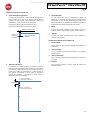
1. Backgage Depth Setting
Backgage is the distance of the punched hole(s) from the trail
edge of the sheet. This distance can be adjusted by entering the
Settings section (press Up or Down from the Home screen, and
press OK for Settings).
Pressing Up arrow will increase the Depth of Backgage, and
Pressing Down arrow will decrease the Depth of Backgage.
2. Alignment Setting
Alignment is the distance of the Top punched hole from the side
edge of the sheet (viewed from the punch output orientation). This
distance can be adjusted by entering the Settings section (press
Up or Down arrow from the Home screen, and press OK for
Settings). Pressing Up arrow will increase the Alignment position,
and Pressing Down arrow will decrease the Alignment position.
3. Clear Cover
Use this setting to adjust the Backgage depth and Alignment
setting for Clear Cover media. Adjusting this offset does not affect
the Backgage and Alignment settings of other media types.
4. Language
The LCD panel can be configured to display one of the
following languages: English; Francais; Espanol; Deutsch or
Italiano.
5. Units
The LCD panel can be configured to display units in MM or
Inches.
Displaying Information on the LCD Panel
1. Die type
This is type of die-set currently installed in the punch.
2. Die cycles
This is the total number of sheets punched with the currently
installed die-set.
3. Punch cycles
This is the total number of punched sheets the system has
processed.
4. Firmware
This displays the current level of firmware of StreamPunch
Ultra.
BACKGAGE
“-”ON THE LCD
DECREASES
BACKGAGE
DEPTH
“+”ON THE LCD
INCREASES
BACKGAGE
DEPTH
ALIGNEMENT
“+” ON THE LCD
INCREASES
ALIGNMENT
OFFSET
“-” ON THE LCD
DECREASES
ALIGNMENT
OFFSET
All manuals and user guides at all-guides.com

9
GB
StreamPunchTM Ultra/Ultra MP
6. PROBLEM SOLVING
Probable Cause
Probable Cause
No power, won’t punch
Power cord not attached to back
of machine or not properly
plugged into the wall.
Punched holes not aligned with
the edge of the paper
Follow instructions on die set
labels to properly configure the
die for a specific sheet size
When punching with paper of
270-300 gsm with grain
orientation in the direction of
paper flow, paper jams may occur
depending on the stiffness of the
media. Using a different, less
rigid, cover media may remove
the problem.
Sheet jamming repeatedly at die
set area.
Remove the die-set, inspect the
die throat to see if there is any
stuck paper chad.
Check that printed sheets do not
have excess curl. Make efforts to
reduce curl to the minimum
possible. Review the printer
manual to reduce this if present.
When punching with paper of
270-300 gsm with grain
orientation in the direction of
paper flow, paper jams may occur
depending on the stiffness of the
media. Using a different, less
rigid, cover media may remove
the problem.
Insert Chip tray message on the
LCD interface.
Make sure the Chip tray is fully
inserted.
7. SPECIFICATIONS
Speed
Up to 136 sheets per minute
Punch Sheet Size and
Edge
LEF- Long Edge Fed
SEF- Short Edge Fed
Tab Stock
US Sizes
LTR LEF
LTR SEF
LTR SEF Double Punch
Statement LEF
Legal SEF
Ledger SEF
Ledger SEF Double Punch
ISO sizes
A4 LEF
A4 SEF
A4 SEF Double Punch
A5 LEF
A3 SEF
A3 SEF Double Punch
US Sizes
LTR, with 3,4,5,8 and 10 tabs
Statement, with 3 and 5 tabs
ISO Sizes
A4, with 5 and 10 tabs
A5, with 3 and 5 tabs
Paper Stock
Clear Cover
Plain: 75gsm - 300gsm
(20# bond to 110# cover)
Coated: 120gsm - 300gsm
(32# bond to 110# cover)
7mil
Bypass mode stock and
sizes
Paper sizes and stocks same as
printer
Punch Capacity
Single Sheet
Power Supply
115V, 60Hz, Single Phase
230V, 50Hz, Single Phase
Electrical
Amps and
Frequency
115V; 3.8A; 60Hz (or)
230V; 1.9A; 50Hz
Safety Certification
cULus
Dimensions
L: 730mm; W: 445mm; H: 1000mm
L: 29"; W: 17.5"; H: 39.5"
Weight
96 kg
212 lbs
Shipping Weight
127 kg
280 lbs.
Manufactured
Assembled in Taiwan
All manuals and user guides at all-guides.com

10
GB
StreamPunchTM Ultra/Ultra MP
8. DIE SET USER MANUAL
The die sets for the StreamPunch Ultra are intended to work with
multiple paper sizes and sheet feed directions. In order to
accommodate different sheet sizes this die set must be configured to
the correct number of punching pins and the die stop must be set to
the proper position. The die label contains information on the common
paper punching sizes, for the uncommon sizes please refer to Table 1.
Glossary
LEF- Long Edge Feed- Indicates that the paper is being fed through
the machine so that the longer side of the sheet will be punched.
SEF- Short Edge Feed- Indicates that the paper is being fed through
the machine so that the shorter side of the sheet will be punched.
Statement (STMT) Paper- 8.5" X 5.5"
Legal Paper- 8.5" X 14"
Ledger Paper- 11" X 17"
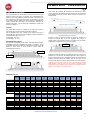
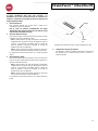
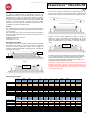
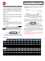
Pin Numbering
Die punching pins are numbered sequentially starting from the handle
end. Figure 8.1 shows a 47 hole coil die (404757) as an example. All
square and round hole die sets follow the same pin numbering format.
Figure 8.1 Coil Die Set Pin Numbering
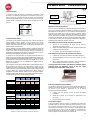
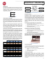
Figure 8.2 Pressure Bar Removal
To remove punch pins from the StreamPunch Ultra first turn the two
Quarter Turn Fasteners counter clockwise to release the pressure bar.
Remove the pressure bar and set aside.
Figure 8.3 Pressure Bar
Figure 8.3 Pin Removal
Lift up and remove the desired pins according to Table 8.1. Store pins
in the pin storage tray inside front door of machine making sure pins
cannot be dropped, damaged or lost while removed.
Figure 8.4 Replace Pressure Bar
Replace the pressure bar by lining up dowel pin holes with exposed
dowel pins. Hold pressure bar so that it is seats completely over dowel
pins and then rotate Quarter Turn Fasteners clockwise until a click is
felt to lock pressure bar in position.
Important! Make sure pressure bar is attached and both Quarter Turn
Fasteners are in the locked position prior to inserting the die set into
the machine or serious damage can occur to both the machine and die
set.
Dowel Pin
Holes
Dowel Pin Holes
Pin #1
Pin #47
Quarter Turn
Fastener
Pin Removal
Coil
Rnd/Oval
Wire
2:1
Rnd/Sq
Wire
3:1
Rnd/Sq
3 Hole
8mm
3/5/7
Hole
8mm
2/4
Hole
8mm
2/4
Hole
6.5mm
2/4
Hole
SCAN
VeloBind
11 Hole
LTR
VeloBind
12 Hole
A4
CombBind
eWire
Rnd/Sq
US Paper Sizes
Pin numbers to be removed based on paper size and orientation
Ricoh Part Number
404757
404771
404758
404768
404759
404769
404760
404762
404763
404763
404764
404765
404766
404768
404770
404772
LTR LEF
2, 47
1, 23
1, 34
NONE
3H/5H/7H
N/A
N/A
N/A
NONE
N/A
1, 21
1, 34
LTR SEF
7, 42
NONE
5, 31
N/A
N/A
N/A
N/A
N/A
N/A
N/A
NONE
N/A
STATEMENT LEF
7, 42
NONE
5, 31
N/A
N/A
N/A
N/A
N/A
N/A
N/A
NONE
5, 31
LEGAL SEF
7, 42
NONE
5, 31
N/A
N/A
N/A
N/A
N/A
N/A
N/A
NONE
5, 31
LEDGER SEF
2, 47
1, 23
1, 34
NONE
3H/5H/7H
N/A
N/A
N/A
NONE
N/A
1, 21
1, 34
9" x 12" LEF
1, 2, 47
1, 23
1, 34
NONE
3H/5H/7H
N/A
N/A
N/A
NONE
N/A
1, 21
1, 34
9" x 12" SEF
6, 7, 42, 43
3, 21
5, 31
N/A
N/A
N/A
N/A
N/A
N/A
N/A
3, 19
5, 31
12" x 18" SEF
1, 2, 47
1, 23
1, 34
NONE
3H/5H/7H
N/A
N/A
N/A
NONE
N/A
1, 21
1, 34
Coil
Rnd/Oval
Wire
2:1
Rnd/Sq
Wire
3:1
Rnd/Sq
3 Hole
8mm
3/5/7
Hole
8mm
2/4
Hole
8mm
2/4
Hole
6.5mm
2/4
Hole
SCAN
VeloBind
11 Hole
LTR
VeloBind
12 Hole
A4
CombBind
eWire
Rnd/Sq
ISO Paper Sizes
Pin numbers to be removed based on paper size and orientation
Ricoh Part Number
404757
404771
404758
404768
404759
404769
404760
404762
404763
404763
404764
404765
404766
404768
404770
404772
A4 LEF
NONE
NONE
NONE
N/A
N/A
2H/4H
2H/4H
NONE
N/A
NONE
NONE
NONE
A4 SEF
7, 41
4, 21
5, 30
N/A
N/A
1, 4
1, 4
NONE
N/A
N/A
4, 19
5, 30
A5 LEF
7, 41
4, 21
5, 30
N/A
N/A
1, 4
1, 4
NONE
N/A
N/A
4,19
5, 30
A3 SEF
NONE
NONE
NONE
N/A
N/A
2H/4H
2H/4H
NONE
N/A
NONE
NONE
NONE
SRA4 LEF
NONE
NONE
NONE
N/A
N/A
2H/4H
2H/4H
NONE
N/A
NONE
NONE
NONE
SRA4 SEF
6, 7, 41, 42
4, 21
4, 5, 30, 31
N/A
N/A
1, 4
1, 4
NONE
N/A
N/A
4, 19
4, 5, 30, 31
SRA3 SEF
NONE
NONE
NONE
N/A
N/A
2H/4H
2H/4H
NONE
N/A
NONE
NONE
NONE
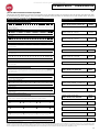
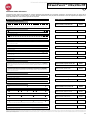
*For CombBind 20H configuration pull Pin Number 1 Table 8.1 Pin Removal Guide
The above chart shows the information on which pins need to be removed to correctly punch each sheet size and configuration that the StreamPunch
Ultra can accept. For standard offering dies not found in the chart no pin adjustment is necessary.
All manuals and user guides at all-guides.com

11
GB
StreamPunchTM Ultra/Ultra MP
Pin Addition
The process for adding punch pins is the same as pin removal except
that pins are added and not removed once the pressure bar is off.
When replacing punch pins make certain that the pins are completely
seated against the pin retainer prior to reattaching the pressure bar.
Figure 8.5 Pin Addition
Die Stop Position
On some of the StreamPunch Ultra die sets there is an adjustable die
stop which is used to re-center the die set for certain sheet sizes, as
shown in Figure 8.7. For die sets without a die stop knob there is no
die stop position adjustment necessary.
For units with a die stop knob, the die stop must be set to the correct
position or the punched holes will not be centered on the sheet. The
common paper sizes are shown on the die stop handle label below the
die stop knob, for the uncommon paper sizes please refer to Table 8.2.
Position A is when the arrow on the die stop knob points down towards
the handle and lines up with the lower arrow on the die stop handle
label. Position B is when the arrow on the die stop knob points to the
side and lines up with the side arrow on the die stop handle label. (See
Figure 8.7)
To change the die stop position first remove the die from the machine
and place on a flat stable surface. While holding the die in a stable
position push down on the die stop knob until the knob is free to rotate.
Then turn the knob until the arrow on the knob lines up with the desired
arrow on the die stop handle label. Once the arrows line up, release
the die stop knob making sure that the metal die stop on the bottom
fully seats against the die plate.
Coil
Rnd/ Oval
Wire
2:1
Rnd/Sq
Wire
3:1
Rnd/Sq
CombBind
eWire
Rnd/Sq
US Paper Sizes
Die Stop Position Based On Paper Size or Orientation
Ricoh Part Number
404757
404771
404758
404768
404759
404769
404768
404770
404772
LTR LEF
B
A
A
A
A
LTR SEF
B
A
B
A
B
STATEMENT LEF
B
A
B
A
B
LEGAL SEF
B
A
B
A
B
LEDGER SEF
B
A
A
A
A
9" x 12" LEF
B
A
A
A
A
9" x 12" SEF
B
A
B
A
B
12" x 18" SEF
B
A
A
A
A
Coil
Rnd/ Oval
Wire
2:1
Rnd
Wire
3:1
Rnd
CombBind
eWire
Rnd/Sq
US Paper Sizes
Die Stop Position Based On Paper Size or Orientation
Ricoh Part Number
404757
404771
404758
404768
404759
404769
404768
404770
404772
A4 LEF
A
A
A
A*
A
A4 SEF
A
A
A
B
A
A5 LEF
A
A
A
B
A
A3 SEF
A
A
A
A*
A
SRA4 LEF
A
A
A
A*
A
SRA4 SEF
A
B
A
B
A
SRA3 SEF
A
A
A
A*
A
*For CombBind 20H Configuration set to die stop position B
Table 8.2 Die Stop Position Guide
Figure 8.7 Coil Die Stop Position
Die Set Maintenance
The StreamPunch Ultra die set must be periodically oiled and greased
to maintain proper functionality and prevent premature failure of the die
set. The die set should be oiled and inspected every 100K cycles.
Before lubricating the die, remove all visible paper dust present,
preferably using compressed air or a clean dry cloth if compressed air
is not available. If compressed air is available, use it to clean out the
area between the top and bottoms plates. Do not used a cloth to clean
this area.
To lubricate die set pins that do not have felt pads:
1. Depress the die set so that the pins protrude from the bottom
plate.
2. Apply a drop of high quality machine oil to the end of each pin.
3. Wipe clean, leaving a light coat of oil on them.
To lubricate die set pins that have felt pads:
1. Lubricate with a high quality machine oil.
2. Apply oil lightly along the length of the pad [1], but do not over
saturate.
3. Do not use spray lubricants because they tend to dry up
quickly and leave a sticky residue.
Oil from the die may blemish the first few punched sheets after oil
has been applied. Run test punched copies until clean copies can
be made.
Figure 8.8 Lubrication
Die Set Shoulder Bolts
The die set shoulder bolts must be checked and lubricated as
necessary every 200K cycles. If the grease is missing from the springs
or shoulder bolts [2] then additional grease must be applied.
1. Lubricate with a high quality Teflon-based grease.
2. Apply grease to shoulder bolts and springs [2]
3. Wipe up any excess grease.
End of Die Life
If a die set is at the end of its life it will tend to cause paper jams due to
hanging paper chips. This is a result of die plate wear and not pin
wear, which cannot be corrected. When this occurs, the die set must
be replaced with a new one. Attempting to replace or sharpen pins will
not correct the issue since the wear is in the plates and therefore is not
recommended.
CORRECT INCORRECT
CORRECT INCORRECT
Die Stop
Handle Label
Die Stop Knob
Position A
Position B
All manuals and user guides at all-guides.com

12
GB
StreamPunchTM Ultra/Ultra MP
StreamPunch Ultra Die Sets
The StreamPunch Ultra uses a variety of easily interchangeable die sets that allow you to punch documents in line for several different binding
styles. By selecting the appropriate die set, you can use your StreamPunch Ultra to punch documents in any of the following binding styles.
DuraGlide HDTM die sets are shown in bold where available.
Die Set Description
RICOH Part Number
For Plastic Comb Binding:
Die, RICOH, Comb Bind
Die, RICOH, Comb Bind, HD
404767
409059
PB Plastic Bind; Hole Size: 8mm x 2.9mm (0.313" x 0.116") (LxW); Center-to-Center Hole Spacing: 14.3mm (0.563")
For Twin Loop™ Binding:
Die, RICOH, Wire 3.1, Sq.
404769
W3 Wire; Square; 3 Holes per inch; Hole Size: 4mm x 4mm (0.156" x 0.156") (L x W); Center-to-Center Hole Spacing:
8.5mm (0.333")
Die, RICOH, Wire 2.1, Sq.
404768
W2 Wire; Rectangle; 2 Holes per inch; Hole Size: 6.4mm x 5.4mm (0.250" x 0.214")(L xW); Center-to-Center Hole Spacing:
12.7mm (0.500")
Die, RICOH, eWire, 3:1, Sq.
404770
eWire; Square; 3 Holes per inch; Hole Size: 5mm x 5mm (0.197" x 0.197") (L x W); Center-to-Center Hole Spacing:
8.5mm (0.333")
Die, RICOH, Wire, 3:1, Rnd.
404759
W3 Wire; Round; 3 Holes per inch; Hole Size: 4mm (0.158") Diameter; Center-to-Center Hole Spacing: 8.5mm (0.335")
Die, RICOH, Wire, 2:1, Rnd.
404758
W2 Wire; Round; 2 Holes per inch; Hole Size: 6.5mm (0.0.256") Diameter; Center-to-Center Hole Spacing: 12.7mm (0.5")
Die, RICOH, eWire, 3:1, Rnd.
404772
eWire; Round; 3 Holes per inch; Hole Size: 5.5mm (0.217") Diameter; Center-to-Center Hole Spacing: 8.5mm (0.333")
For Color Coil™ Binding:
Die, RICOH, Coil, Rnd.
Die, RICOH, Coil, Rnd, HD
404757
409057
C4 Coil; Round; 4 Holes per inch; Hole Size: 4.4mm (0.174") Diameter; Center-to-Center Hole Spacing: 6.3mm (0.2475")
Die, RICOH, Coil, Oval
404771
C4 Coil; Oval; 4 Holes per inch; Hole Size: 4mm x 5mm (0.158" x 0.197") (L x W); Center-to-Center Hole Spacing: 6.3mm
(0.2475")
For Velo® Bind:
Die, RICOH, Velobind®, 11 Holes, Ltr.
404765
VB Velobind®; Round; 1 Hole per inch Hole Size: 3.2mm (0.125") Diameter; Center-to-Center Hole Spacing: 25.4mm (1")
Die, RICOH, Velobind®, 12 Holes, A4.
404766
VB Velobind®; Round; 1 Hole per inch Hole Size: 3.2mm (0.126") Diameter; Center-to-Center Hole Spacing: 25.4mm (1")
For Loose Leaf Binding:
Die, RICOH, 3 Hole, 8mm
Die, RICOH, 3 Hole, 8mm, HD
404760
409058
3 Ring Binder; U.S. (Standard Loose-leaf Patterns); Hole Size: 8mm (0.316") Diameter
Die, RICOH, 3/5/7 Hole, 8mm
404761
3 Ring, 5 Ring, 7 Ring; U.S. (Standard Loose-leaf Patterns); Hole Size: 8mm (0.316") Diameter
Die, RICOH, 4 Hole, 8mm
404762
4 Ring Binder; European (Standard Loose-leaf Patterns); Hole Size: 8mm (0.315") Diameter
Die, RICOH, 4 Hole, 6.5mm
404763
4 Ring Binder; European (Standard Loose-leaf Patterns); Hole Size: 6.5mm (0.256") Diameter
Die, RICOH, 4 Hole, Scan
404764
4 Ring Binder; Scandinavian (Standard Loose-leaf Patterns); Hole Size: 6.5mm (0.256") Diameter
©2016 GBC, Lake Zurich, Illinois - All rights reserved. Graphics do not represent actual punch pattern dimensions or spacing.
* When the Plastic Comb binding die is used in the 21 hole configuration on A4 width paper (297mm), there is the potential for the outer edge of holes 1 and 21 to be torn. The theoretical
paper edge should be 1.62mm from the edge of the sheet. This event is dependent on paper type, paper width and hole alignment optimization. To avoid this issue, it is recommended to
use a 20 hole configuration instead. 20 hole comb binding supplies are commonly available from GBC and other manufacturers and are considered more optimal than the 21 hole
configuration.
121-A4
19-LTR
1 34-A432-LTR
123-A4
21-LTR
134
1 32-L 34-A4
TR
123-A4
21-LTR
1 34
147-A444-LTR
147-A444-LTR
1 11
1 12
13
17
4
1 4
1 4
All manuals and user guides at all-guides.com

13
F
StreamPunchTM Ultra/Ultra MP
TABLE DES MATIÈRES
1. CONSIGNES DE SÉCURITÉ 13
Consignes importantes 13
Nettoyage 13
Entretien 14
Messages de sécurité 14
2. INTRODUCTION 14
3. GUIDE DE DÉMARRAGE RAPIDE 15
4. OPÉRATIONS DE L'UTILISATEUR 16
1. CONSIGNES DE SÉCURITÉ
VOTRE SÉCURITÉ ET LA SÉCURITÉ DES PERSONNES QUI VOUS
ENTOURENT SONT TRÈS IMPORTANTES POUR GBC. LES
CONSIGNES ET MESSAGES DE SÉCURITÉ ESSENTIELS
DÉLIVRÉS DANS LE PRÉSENT MANUEL APPARAISSENT
ÉGALEMENT SUR LA MACHINE. VEUILLEZ LIRE ATTENTIVEMENT
CE MANUEL AVANT D’UTILISER LA MACHINE.
DANS CE MANUEL D’UTILISATION, VOUS TROUVEREZ
UN SYMBOLE D’AVERTISSEMENT EN REGARD DE
CHAQUE MESSAGE DE SÉCURITÉ. CE SYMBOLE
SIGNALE UN RISQUE POTENTIEL. VOUS POURRIEZ
VOUS BLESSER, BLESSER UN TIERS OU
ENDOMMAGER LE PRODUIT.
VOUS TROUVEREZ LES ÉTIQUETTES SUIVANTES SUR
L‘STREAMPUNCH ULTRA:
Ce symbole de sécurité signale qu'une
décharge électrique pourrait vous blesser
gravement, voire entraîner la mort si vous
ouvrez la machine. Ne retirez JAMAIS les
couvercles vissés de la machine. Faites
TOUJOURS appel pour la maintenance à un
personnel qualifié.
5. AFFICHAGE DE L'UTILISATEUR 17
6. RÉSOLUTION DES PROBLÈMES 19
7. CARACTÉRISTIQUES TECHNIQUES 19
8. MANUEL D'UTILISATION DES JEUX DE
MATRICES 20
Consignes importantes
Utilisez l’StreamPunch Ultra uniquement pour perforer le papier et
les couvertures conformément aux spécifications indiquées.
Gardez ce manuel d’utilisation à portée de main.
ATTENTION: L’INTERRUPTEUR MARCHE/ARRÊT DE
L’IMPRIMANTE NE MET PAS LA PERFORATRICE HORS
TENSION.
La tension d’alimentation de l’StreamPunch Ultra doit
correspondre aux caractéristiques électriques de la machine (elles
sont indiquées sur l’étiquette du numéro de série).
Une prise de terre est prévue par mesure de sécurité. Elle doit
être raccordée à une prise électrique prévue à cet effet. Si vous
ne parvenez pas à introduire la fiche dans la prise, faites appel à
un électricien qualifié pour qu’il installe une prise adéquate.
Ne modifiez pas la fiche située au bout du cordon d’alimentation
de l’StreamPunch Ultra (si elle est fournie). Elle a été conçue pour
votre sécurité.
Débranchez l’StreamPunch Ultra avant de déplacer la machine ou
si vous prévoyez de ne pas l’utiliser durant une longue période.
N’utilisez pas l‘StreamPunch Ultra si le cordon ou la fiche
d’alimentation de la machine est endommagé. N’utilisez pas la
machine après un quelconque dysfonctionnement. Ne mettez pas
la machine sous tension si vous avez renversé un liquide ou si
elle est endommagée de quelque façon que ce soit.
Ne surchargez pas les prises électriques. Cela pourrait provoquer
un incendie ou une décharge électrique.
Nettoyage
Vous pouvez nettoyer la surface externe de l’StreamPunch Ultra à
l’aide d’un chiffon doux et humide.
N’utilisez pas de détergent ou de solvants, car vous pourriez
endommager la machine.
All manuals and user guides at all-guides.com

14
F
StreamPunchTM Ultra/Ultra MP
Messages de sécurité
SÉLECTION DU CORDON D’ALIMENTATION SECTEUR
(LE PARAGRAPHE SUIVANT NE S’APPLIQUE QU’AUX MODÈLES
ALIMENTÉS PAR UN COURANT DE 230V 50Hz UTILISÉS DANS
L’UNION EUROPÉENNE.)
ATTENTION: LORSQUE VOUS CHOISISSEZ UN CORDON
D’ALIMENTATION AMOVIBLE POUR VOTRE
STREAMPUNCH ULTRA, RESPECTEZ TOUJOURS LES
PRÉCAUTIONS SUIVANTES.
Le cordon est constitué de trois parties: la fiche, le cordon et la
connexion à la machine. Chacun de ces composants dispose de
l’homologation européenne requise en matière de sécurité.
Les caractéristiques électriques minimales applicables au cordon sont
publiées pour des raisons de sécurité.
N’UTILISEZ PAS DE CORDONS NE RESPECTANT PAS LES
EXIGENCES ÉLECTRIQUES MINIMALES SUIVANTES.
FICHE: 3 A, 250V, 50/60Hz, Classe 1, à 3 conducteurs, homologue par
l'Union Européenne.
CORDON: Type H05VV-F3G0.75, harmonisé (< HAR >). Les symbols
«< >» indiquent que le cordon est homologué conformément à la
norme européenne appropriée (REMARQUE: «HAR» équivaut à la
marquee d’homologation de l’agence de sécurité européenne qui a
approuvé le cordon. Exemple: «< VDE >»).
CONNECTEUR DE L’APPAREIL: 3 A, 250V, 50/60Hz, homologué par
l’Union Européenne, type IEC 320. Le cordon ne doit pas excéder 3 m
de long. Vous pouvez remplacer le cordon électrique par un cable
d'alimentation présentant des caractéristiques électriques supérieures
aux minima indiqués.
NOTE FCC
(LE PARAGRAPHE SUIVANT NE S’APPLIQUE QU’AUX MODÈLES
ALIMENTÉS PAR UN COURANT DE 115V 60Hz.)
Cet équipement a été testé et il satisfait aux normes relatives aux
appareils numériques de Classe A, conformément à la Partie 15 des
règles FCC. Ces limites ont été prévues pour garantir une protection
raisonnable contre les interférences nocives lors de l’utilisation de
l’équipement dans une zone de travail.
Cet équipement génère, utilise et irradie des ondes radio. Par
conséquent, si vous ne l’installez pas ou ne l’utilisez pas conformément
au manuel d’utilisation, vous risquez de provoquer des interferences
dans les communications par radio. L’utilisation de cet équipement
dans une zone habitée risque de provoquer des interférences. Dans ce
cas, vous devrez corriger ces interférences à vos frais.
CAN ICES-3 (A)/NMB-3(A)
MISE EN GARDE: TOUTE MODIFICATION EFFECTUÉE
SUR CET APPAREIL QUI NE SERAIT PAS APPROUVÉE
PAR GBC PEUT ANNULER L'AUTORISATION
ACCORDÉE À L'UTILISATEUR PAR LA FCC ET/OU
L'INDUSTRIE AU CANADA D'UTILISER CET
ÉQUIPEMENT.
Entretien, StreamPunch Ultra
Ne tentez pas de réparer votre StreamPunch Ultra par vous-même.
Contactez un représentant agréé pour effectuer les réparations ou le
gros entretien de votre StreamPunch Ultra.
NE RETIREZ PAS LES COUVERCLES DE LA MACHINE.
AUCUNE pièce interne ne peut être remplacée par l’utilisateur. Les
risques de blessure et/ou d’endommagement de la machine sont ainsi
éliminés.
Entretien des matrices
Chaque matrice doit être soigneusement lubrifiée en usine avant d’être
livrée au client. Dans des conditions normales d’utilisation, ce lubrifiant
disparaît progressivement et doit être remplacé. Dans le cadre d'une
maintenance régulière, chaque jeu de matrices doit être lubrifié.
Voir en Section 8 le manuel d'instructions pour jeu de matrices
StreamPunch Ultra sur l'entretien des jeux de matrices.
2. INTRODUCTION
Nous tenons à vous remercier d’avoir acheté un StreamPunch Ultra.
Ce système de production polyvalent vous permettra de perforer des
documents de nombreuses manières en remplaçant tout simplement le
bloc à colonnes. Cet appareil a été conçu dans un souci de simplicité
d'utilisation.
L’StreamPunch Ultra est une solution innovante pour perforer le papier.
Il offre en outre les caractéristiques suivantes:
Les blocs à colonnes peuvent être remplacés rapidement sans
outil ni levier.
Tous les blocs à colonnes de l’StreamPunch Ultra disposent d’une
étiquette d'identification indiquant la configuration de perforation et
son nom.
Zone de stockage pratique pour deux jeux de matrices.
Cycle de service et positionnement du produit
Le GBC StreamPunch Ultra offre une solution de perforation souple et
rentable pour des environnements de production de perforations de
niveau léger à moyen. Il est conçu pour les utilisateurs d'imprimantes
qui ont généralement besoin de perforer leurs documents à une
moyenne de 20 à 30% de leur flux de travail total. Pour les clients qui
effectuent de longues perforations de plus de 4 heures, les
performances peuvent varier ou se dégrader en raison d'une large
gamme de poids et de conditions environnementales qui peuvent se
produire.
AMPV - Volume nominal moyen mensuel de 600 000 impressions
(A4/lettre), si le volume est réparti à 50/50 entre la perforation et la
dérivation (300 000 perforations et 300 000 dérivations).
Volume mensuel maximum recommandé - Le volume de
perforations mensuel maximum recommandé ne doit PAS dépasser
400 000.
Cycle de service maximum de perforations - Outre les conditions
sus-mentionnées, pas plus de 2 feuilles de 300 gsm sur 5 feuilles de 75
gsm doivent être perforées. Les stocks de papier le plus lourd sont
généralement utilisés comme pages de couverture et dernières pages
pour l'application de reliure de livres.
Fourniture de jeux de matrices de fonctionnement
Les matrices sont considérées comme des consommables et doivent être
remplacées lorsqu'elles sont usées, car il est impossible de les aiguiser.
Chaque jeu de matrices possède une garantie de 90 jours après la
date d'achat. La garantie est annulée si la matrice est utilisée en
dehors de ses spécifications.
La durée de vie des matrices de perforation peut être prolongée si elle
est lubrifiée tous les 100 000 cycles de perforation (voir Entretien des
jeux de matrices pour les détails)
Les jeux de matrices ont une durée d'utilisation prévue de 750 000
perforations avec du papier de 20 lb/75 gsm. Il s'agit uniquement d'une
prévision de durée de vie. La durée de vie des matrices n'est PAS
garantie en raison de la large gamme de poids des supports et de
conditions environnementales que les matrices peuvent supporter. Si
vous prévoyez de perforer pendant de longues durées qui dépassent la
durée de vie des matrices, il est fortement recommandé d'avoir un
nombre suffisant de jeux de matrices appropriées pour continuer avec
un minimum de temps d'arrêt.
All manuals and user guides at all-guides.com

15
F
StreamPunchTM Ultra/Ultra MP
3. GUIDE DE DÉMARRAGE RAPIDE
Le StreamPunch Ultra doit être raccordé au courant CA du secteur
pour pouvoir activer l'une des fonctions de l'appareil. Ci-dessous
sont indiqués les trois modes de fonctionnement du StreamPunch
Ultra.
1. Mode derivation:
Cette opération permet au papier de passer par l’StreamPunch Ultra
sans être perforé.
C'est le mode de fonctionnement par défaut du StreamPunch
Ultra. Assurez-vous que l'icône Punch (perforation) n'est pas
sélectionné dans l'Interface utilisateur de l'imprimante.
2. Mode perforation simple:
Cette opération permet de perforer le bord arrière de toutes les
feuilles passant par l'StreamPunch Ultra.
Étape 1: Un jeu de matrices correctement configuré doit être
introduit avant de lancer le mode perforation. Voir en section 4.A
les détails sur le changement des jeux de matrices et suivre les
étiquettes sur la configuration des jeux de matrices.
Étape 2: Avant de commencer une tâche d'impression,
sélectionnez l'icône Punch (perforation simple) pour activer la
perforation.
L'StreamPunch Ultra fonctionne désormais en mode Perforation
simple.
3. Mode Perforation double:
Cette opération permet de perforer les deux rangées de trous: une
au milieu de la feuille et l'autre adjacente au bord arrière de toutes
les feuilles qui passent dans l'StreamPunch Ultra.
Étape 1: Un jeu de matrices correctement configuré doit être
introduit avant de lancer le mode perforation. Voir en section 4.A
les détails sur le changement des jeux de matrices et suivre les
étiquettes sur la configuration des jeux de matrices.
Étape 2: Avant de commencer une tâche d'impression,
sélectionnez l'icône Double Punch (perforation double) pour
activer la perforation.
L'StreamPunch Ultra fonctionne désormais en mode Perforation
double.
Disposition de l'interface utilisateur LCD de l'StreamPunch Ultra
4. Configuration du jeu de matrices
Pour configurer le jeu de matrices au format désiré de la feuille en
cours de traitement, voir la section 8 - Manuel d'utilisation des jeux
de matrices.
HAUT
BAS
ENTRER/
OK
All manuals and user guides at all-guides.com

16
F
StreamPunchTM Ultra/Ultra MP
4. OPÉRATIONS UTILISATEUR
A. Permutation des jeux de matrices:
S'effectue sans outils et ne prend que quelques secondes
B. Récipient à confettis:
Bac à confettis facile d'accès pour l'élimination rapide des
confettis
C. Stockage des matrices:
Prévu pour stocker jusqu’à deux matrices
D. By-pass perforatrice:
Chemin papier court et direct pour les documents non perforés
E. Chemin papier en mode perforation:
Le grand rayon de la courbe permet d’utiliser des supports d’un
grammage allant jusqu’à 300g/m2.
Débit de papier et sections interactives utilisateur de l'StreamPunch Ultra
A. Permutation des jeux de matrices:
Votre StreamPunch Ultra utilise des matrices interchangeables, ce qui
vous permet de perforer, à moindres frais, les documents en fonction
de différents styles de reliure. Le remplacement des matrices de la
machine est rapide et facile. Pour ce faire, suivez les instructions
suivantes:
Remarque: Pour les instructions sur la configuration avancée des jeux
de matrices, voir la section 8 Manuel d'utilisation des jeux de matrices.
Retrait des matrices de la machine: La fente pour jeu de matrice
interchangeable du StreamPunch Ultra est située à côté du bac à
déchets de perforation au fond de la perforatrice.
Étape 1: Arrêter l'imprimante/copieur.
Étape 2: Ouvrir le panneau de la porte d'accès de l'StreamPunch
Ultra.
Étape 3: Saisir fermement la poignée de blocage de la matrice et
la tourner dans le sens anti-horaire, comme indiqué sur l'étiquette
située à côté de la poignée. Ceci permet de débloquer la matrice.
Étape 4: Faire glisser le jeu de matrices jusqu'à le retirer
entièrement, en le soutenant des deux mains.
Étape 5: Ranger soigneusement le jeu de matrices extrait dans
l'espace de rangement des jeux de matrices. (le protéger de la
poussière, des salissures, des chutes accidentelles du bord des
compteurs, etc.).
Étape 6: Choisir le jeu de matrices désiré pour votre nouvelle
tâche et le glisser dans la fente du jeu de matrices. Pousser
fermement le jeu de matrices jusqu'à ce que le dispositif d'arrêt de
la matrice soit en contact avec l'aimant rond. Ceci est primordial
pour s'assurer de la bonne position du jeu de matrices.
Étape 7: Saisir la poignée et la tourner dans le sens horaire,
jusqu'à ce que le loquet soit complètement engagé, comme illustré
sur l'étiquette.
ATTENTION: FAITES ATTENTION DE NE PAS VOUS
COINCER LES DOIGTS. LORS DE LA MISE EN PLACE DE
LA MATRICE DANS L’STREAMPUNCH ULTRA, ÉLOIGNEZ
VOS DOIGTS DE LA FENTE POUR MATRICE ET NE TENEZ
LA MATRICE QU’À L’AIDE DE L’ORIFICE PRÉVU À CET
EFFET. SOYEZ PRUDENT, CAR VOUS POURRIEZ VOUS
BLESSER.
Étape 8: Fermez la porte d’accès.
Étape 9: Poursuivez votre travail d’impression/perforation.
À noter que lorsque vous utilisez une matrice neuve, quelques traces
d’huile peuvent être présentes autour des trous de perforation de la
feuille. Après environ 25 à 50 feuilles, la matrice ne laissera plus
aucune trace d’huile sur les feuilles. Il est recommandé d’effectuer un
court test d’impression après avoir installé une matrice neuve ou
récemment lubrifiée.
B. Récipient à confettis:
Le réservoir à confettis de perforation pour l'StreamPunch Ultra est
situé à l'avant de la base de la machine. Le tiroir doit être régulièrement
retiré et vidé. L'StreamPunch Ultra utilise un capteur pour déterminer
quand le réservoir à confettis est plein. Une fois que le réservoir à
confettis est plein, l'écran LCD affiche le message «Chip Tray Full»
(Bac à confettis plein) et un message apparaît également sur l'écran de
l'interface utilisateur de l'imprimante.
All manuals and user guides at all-guides.com

17
F
StreamPunchTM Ultra/Ultra MP
C. Dégagement du papier:
Lorsque du papier est coincé dans le passage de
papier de l'StreamPunch Ultra, l'écran LCD
indique la zone où les feuilles sont coincées.
Zone
Description
Si du papier est coincé en Zone 1, soulever la
plaque de guidage du papier située à l'intérieur,
atteindre le papier coincé et le retirer. Pour fermer
le guide de papier, soulever la poignée pour
débloquer le mécanisme et le refermer
fermement.
Si du papier est coincé en Zone 2, déplacer la
porte vers la droite, atteindre le papier coincé et
le retirer.
Si du papier est coincé en Zone 3, appuyer sur le
levier du haut tout en maintenant celui du bas.
Ceci permet de déverrouiller la chute ; continuer à
ouvrir la chute jusqu'à ce qu'elle atteigne l'aimant
du côté droite. Atteindre et retirer le papier. Pour
ramener la chute en position fermée, la déplacer
dans le sens opposé jusqu'à ce que le
mécanisme de verrouillage soit active.
Si du papier est coincé en Zone 5, débloquer la
goulotte, atteindre le papier coincé et le retirer.
Si du papier est coincé en Zone 6, déplacer la
porte vers la gauche, atteindre le papier coincé et
le retirer.
Avant de retirer le jeu de matrices, s'assurer qu'il
n'existe pas de papier coincé dans les Zones 3 et
5. Si aucun papier ne se trouve en Zone 3 et 5,
déposer le jeu de matrices pour retirer tout le
papier coincé. (Voir Section 4. Changement des
jeux de matrices interchangeables).
5. AFFICHAGE DE L'UTILISATEUR . OPERATION CONTROLS
À l'avant de l'StreamPunch Ultra se trouve un panneau LCD interactif
utilisateur qui affiche des messages, des paramètres et des
informations relatives aux fonctions de la poinçonneuse.
Aperçu du panneau LCD
Messages sur le panneau LCD
1. Dérivation prêt
L'StreamPunch Ultra est prêt à passer en mode dérivation, les
feuilles ne seront pas perforées.
2. Matrice simple prêt
L'StreamPunch Ultra est prêt à effectuer une tâche de perforation,
toutes les feuilles dans l'appareil vont être perforées.
3. Perforation double prêt
L'StreamPunch Ultra est prêt à effectuer une tâche de perforation,
toutes les feuilles dans l'appareil vont être perforées en leur milieu
et le long du bord arrière.
4. Lancement Dérivation
Ceci est affiché lorsque le mode de Dérivation est activé.
5. Lancement Matrice simple
Ceci est affiché lorsque le mode de Perforation simple est activé.
6. Lancement Matrice double
Ceci est affiché lorsque le mode de Perforation double est activé.
7. Bac à confettis plein
Lorsque le réservoir à confettis se remplit de confettis de papier,
ce message s'affiche.
8. Bac à confettis sorti
Lorsque le réservoir à confettis est retiré ou mal inséré dans la
perforatrice, ce message s'affiche.
9. Vérifier la matrice
Lorsque le jeu de matrices est retiré ou mal inséré dans la
perforatrice, ce message s'affiche. Lorsque ce message s'affiche,
la perforatrice démarre en mode Dérivation uniquement.
10. Fermer la porte
Lorsque la porte avant est ouverte ou mal fermée, ce message
s'affiche.
11. Bourrage papier
Lorsqu'une feuille de papier se coince dans la perforatrice, ce
message s'affiche. Voir dans la section de ce manuel intitulée
DÉGAGEMENT PAPIER les instructions sur la façon de retirer
une feuille coincée.
All manuals and user guides at all-guides.com

18
F
StreamPunchTM Ultra/Ultra MP
Modification des paramètres sur le panneau LCD
1. Réglage de profondeur de marge
La marge est la distance entre le(s) trou(s) de perforation et le bord
arrière de la feuille. Cette distance peut être réglée en accédant à la
section Paramètres (appuyer sur «Up» (haut) ou «Down» (bas) sur
l'écran d'accueil et appuyer sur OK pour les Paramètres).
Une pression sur la flèche «Up» augmente la profondeur de la
marge et
Une pression sur la flèche «Down» diminue la profondeur de la
marge.
2. Réglage de l'alignement
L'alignement est la distance entre le trou de perforation du haut et
le bord latéral de la feuille (vue à partir du sens de sortie de la
perforation). Cette distance peut être réglée dans la section
Paramètres (appuyer sur la flèche Up (haut) ou Down (bas) sur
l'écran d'accueil et appuyer sur OK pour les Paramètres). Une
pression sur la flèche Up (haut) augmente la position de
l'alignement et une pression sur la flèche Down (bas) diminue la
position de l'alignement.
3. Effacer écartement
Utiliser ce réglage pour ajuster la profondeur de l'espace arrière et
le paramètre d'alignement pour le couvercle transparent. Le
réglage de cet écart n'affecte pas l'espace arrière et les
paramètres d'alignement d'autres types de supports.
4. Langue
Le panneau LCD peut être configuré pour afficher l'une des
langues suivantes: English; Francais; Espanol; Deutsch ou
Italiano.
5. Unités
Le panneau LCD peut être configuré pour afficher les unités
en mm ou en pouces.
Affichage des informations sur le panneau LCD
1. Type de Matrice
Il s'agit du type de jeu de matrices actuellement installé dans
la perforatrice.
2. Cycles de matrices
C'est le nombre total de feuilles perforées avec le jeu de
matrices actuellement installé.
3. Cycles de perforation
C'est le nombre total de feuilles perforées que le système a
traité.
4. Micrologiciel
Ceci affiche le niveau actuel du logiciel d'StreamPunch Ultra.
MARGE
«+» SUR LE LCD AUGMENTE
LA PROFONDEUR DE LA MARGE
«-» SUR LE LCD
DIMINUE LA
PROFONDEUR
DE LA MARGE
«+» SUR LE LCDAUGMENTE
L'ÉCART D'ALIGNEMENT
ALIGNEMENT
«-» SUR LE LCD DIMINUE
L'ÉCART D'ALIGNEMENT
All manuals and user guides at all-guides.com

19
F
StreamPunchTM Ultra/Ultra MP
6. RÉSOLUTION DES PROBLÈMES
Cause probable
Cause probable
Pas d'alimentation, pas de
perforation
Le cordon d'alimentation n'est
pas fixé à l'arrière de la machine
ou n'est pas correctement
branché à la prise murale.
Les trous perforés ne sont pas
alignés avec le bord du papier
Suivre les instructions sur les
étiquettes des jeux de matrices
pour configurer correctement la
matrice pour un format spécifique
Lors de la perforation de papier
de 270-300 gsm avec l'orientation
du grain dans le sens de
circulation du papier, des
bourrages peuvent se produire en
fonction de la rigidité du support.
L’utilisation d'un support de
couverture différent, moins rigide,
peut résoudre ce problème.
Bourrage de feuilles répété au
niveau du jeu de matrices.
Retirer le jeu de matrices,
examiner la gorge des matrices
pour rechercher d'éventuels
confettis coincés.
Vérifier que les feuilles imprimées
ne sont pas trop incurvées.
S’efforcer de réduire le plus
possible le gondolage au
minimum. Le cas échéant,
consulter le manuel de
l'imprimante pour réduire ce
problème.
Lors de la perforation de papier
de 270-300 gsm avec l'orientation
du grain dans le sens de
circulation du papier, des
bourrages peuvent se produire en
fonction de la rigidité du support.
L’utilisation d'un support de
couverture différent, moins rigide,
peut résoudre ce problème.
Insérer un message de bac à
confettis sur l'interface LCD
S'assurer que le bac à confettis
est complètement introduit.
7. CARACTÉRISTIQUES TECHNIQUES
Vitesse
Jusqu'à 136 feuilles par minute
Dimensions et bord de
la feuille perforée
LEF- Alimentation bord
long
SEF- Alimentation bord
court
Stock de onglet
Formats US
LTR LEF
LTR SEF
LTR SEF Double perforation
Statement LEF
Legal SEF
Ledger SEF
Ledger SEF Double perforation
Formats ISO
A4 LEF
A4 SEF
A4 SEF Double perforation
A5 LEF
A3 SEF
A3 SEF Double perforation
Formats US
LTR, 3,4,5,8 et 10 et onglets
Statement, avec 3 et 5 onglets
Formats ISO
A4, avec 5 et 10 onglets
A5, avec 3 et 5 onglets
Stock de papier
Couvercle transparent
Simple: 75gsm - 300gsm
(20# reliure à 110# couverture)
Couché: 120gsm - 300gsm
(32# reliure à 110# couverture)
7mil
Stock et formats en
mode Dérivation
Formats de papier et stocks identiques
à ceux de l'imprimante
Capacité de perforation
Feuille simple
Alimentation électrique
115V, 60Hz, Monophase
230V, 50Hz, Monophase
Électricité
Ampères et
Fréquence
115V; 3.8A; 60Hz (ou)
230V; 1.9A; 50Hz
Certification de sécurité
cULus
Dimensions
L: 730mm; W: 445mm; H: 1000mm
L: 29"; W: 17.5"; H: 39.5"
Poids
96 kg
212 livres
Poids d’expédition
127 kg
280 livres
Fabriqué
Assemblé à Taïwan
All manuals and user guides at all-guides.com

21
F
StreamPunchTM Ultra/Ultra MP
8. DIE SET USER MANUAL
Les jeux de matrices de l'StreamPunch Ultra peuvent travailler avec
plusieurs formats de papier et plusieurs sens d'alimentation des
feuilles. Pour accepter différents formats de feuilles, cette matrice doit
être configurée au bon nombre de poinçons de perforation et la butée
de la matrice doit être réglée à la bonne position. L'étiquette de la
matrice comporte des informations sur les dimensions classiques de
perforation du papier ; pour les dimensions inhabituelles, veuillez vous
reporter au Tableau 1.
Glossaire
LEF- Alimentation bord long - Indique que le papier passe dans la
machine de façon que le bord long de la feuille soit perforé.
SEF- Alimentation bord court - Indique que le papier passe dans la
machine de façon que le bord court de la feuille soit perforé.Statement
Format Relevé (STMT) - 8.5" X 5.5"
Format Légal - 8.5" X 14"
Format Ledger - 11" X 17"
Numérotation des poinçons
Les poinçons de perforation de la matrice sont numérotés de manière
séquentielle à partir de l'extrémité de la poignée. La Figure 8.1 montre
un exemple de matrice à bobine à 47 trous (404757). Tous les jeux de
matrices à trous carrés et ronds suivent le même format de
numérotation des poinçons.
Figure 8.1 Numérotation des poinçons du jeu de matrice à bobine
Figure 8.2 Dépose de la barre de pression
Pour retirer des poinçons de perforation de l'StreamPunch Ultra,
tourner d'abord les deux fixations quart de tour dans le sens antihoraire
pour dégager la barre de pression. Retirer la barre de pression et la
mettre de côté.
Figure 8.3 Barre de pression
Figure 8.3 Retrait des poinçons
Soulever et retirer les poinçons désirés en suivant le Tableau 8.1.
Ranger les poinçons dans le bac de rangement des poinçons à
l'intérieur de la porte avant de la machine, en veillant à ne pas heurter,
endommager ou perdre des poinçons en les retirant.
Figure 8.4 Remplacer la barre de pression
Remplacer la barre de pression en alignant les trous des poinçons de
guidage avec les poinçons de guidage apparents. Tenir la barre de
pression de façon qu'elle soit complètement posée sur les poinçons de
guidage, puis faire tourner les fixations quart de tour dans le sens
horaire jusqu'à ressentir un déclic pour verrouiller la barre de pression.
Important ! S'assurer que la barre de pression est bien fixée et que les
deux fixations quart de tour est en position verrouillée avant
d'introduire le jeu de matrices dans la machine, pour éviter de graves
dégâts sur la machine et le jeu de poinçons.
Retrait des poinçons
Bobine
Ronde/Ovale
Fil
2:1
Ronde/ Carré
Fil
3:1
Ronde/ Carré
3 Trou
8mm
3/5/7
Trou
8mm
2/4
Trou
8mm
2/4
Trou
6.5mm
2/4
Trou
numérisat
VeloBind
11 Trou
LTR
VeloBind
12 Trou
A4
CombBind
eWire
Ronde/ Carré
Format de papier US
Position des arrêts de matrice selon le format ou l'orientation du papier
Référence Ricoh
404757
404771
404758
404768
404759
404769
404760
404762
404763
404763
404764
404765
404766
404768
404770
404772
LTR LEF
2, 47
1, 23
1, 34
AUCUN
3H/5H/7H
AUCUN
AUCUN
AUCUN
AUCUN
AUCUN
1, 21
1, 34
LTR SEF
7, 42
AUCUN
5, 31
AUCUN
AUCUN
AUCUN
AUCUN
AUCUN
AUCUN
AUCUN
AUCUN
5, 31
STATEMENT LEF
7, 42
AUCUN
5, 31
AUCUN
AUCUN
AUCUN
AUCUN
AUCUN
AUCUN
AUCUN
AUCUN
5, 31
LEGAL SEF
7, 42
AUCUN
5, 31
AUCUN
AUCUN
AUCUN
AUCUN
AUCUN
AUCUN
AUCUN
AUCUN
5, 31
LEDGER SEF
2, 47
1, 23
1, 34
AUCUN
3H/5H/7H
AUCUN
AUCUN
AUCUN
AUCUN
AUCUN
1, 21
1, 34
9" x 12" LEF
1, 2, 47
1, 23
1, 34
AUCUN
3H/5H/7H
AUCUN
AUCUN
AUCUN
AUCUN
AUCUN
1, 21
1, 34
9" x 12" SEF
6, 7, 42, 43
3, 21
5, 31
AUCUN
AUCUN
AUCUN
AUCUN
AUCUN
AUCUN
AUCUN
3, 19
5, 31
12" x 18" SEF
1, 2, 47
1, 23
1, 34
AUCUN
3H/5H/7H
AUCUN
AUCUN
AUCUN
AUCUN
AUCUN
1, 21
1, 34
Bobine
Ronde/Ovale
Fil
2:1
Ronde/ Carré
Fil
3:1
Ronde/ Carré
3 Trou
8mm
3/5/7
Trou
8mm
2/4
Trou
8mm
2/4
Trou
6.5mm
2/4
Trou
numérisat
VeloBind
11 Trou
LTR
VeloBind
12 Trou
A4
CombBind
eWire
Ronde/ Carré
Format de papier US
Position des arrêts de matrice selon le format ou l'orientation du papier
Référence Ricoh
404757
404771
404758
404768
404759
404769
404760
404762
404763
404763
404764
404765
404766
404768
404770
404772
A4 LEF
AUCUN
AUCUN
AUCUN
AUCUN
AUCUN
2H/4H
2H/4H
AUCUN
AUCUN
AUCUN
AUCUN
AUCUN
A4 SEF
7, 41
4, 21
5, 30
AUCUN
AUCUN
1, 4
1, 4
AUCUN
AUCUN
AUCUN
4, 19
5, 30
A5 LEF
7, 41
4, 21
5, 30
AUCUN
AUCUN
1, 4
1, 4
AUCUN
AUCUN
AUCUN
4,19
5, 30
A3 SEF
AUCUN
AUCUN
AUCUN
AUCUN
AUCUN
2H/4H
2H/4H
AUCUN
AUCUN
AUCUN
AUCUN
AUCUN
SRA4 LEF
AUCUN
AUCUN
AUCUN
AUCUN
AUCUN
2H/4H
2H/4H
AUCUN
AUCUN
AUCUN
AUCUN
AUCUN
SRA4 SEF
6, 7, 41, 42
4, 21
4, 5, 30, 31
AUCUN
AUCUN
1, 4
1, 4
AUCUN
AUCUN
AUCUN
4, 19
4, 5, 30, 31
SRA3 SEF
AUCUN
AUCUN
AUCUN
AUCUN
AUCUN
2H/4H
2H/4H
AUCUN
AUCUN
AUCUN
AUCUN
AUCUN
*Pour une configuration CombBind 20H tirer le poinçon n° 1
Tableau 8.1 Guide de retrait des broches
Le tableau ci-dessus donne des informations sur les poinçons qui doivent être retirés pour perforer correctement chaque format de feuille et la
configuration que l'StreamPunch Ultra peut accepter. Pour les matrices standard ne figurant pas dans le tableau, aucun réglage des poinçons n'est
nécessaire.
Poinçon n° 1
Poinçon n° 47
Système de fixation
quart
Dowel Pin
Holes
Trous des
poinçons
Trous des
poinçons de
guidage
All manuals and user guides at all-guides.com
La pagina si sta caricando...
La pagina si sta caricando...
La pagina si sta caricando...
La pagina si sta caricando...
La pagina si sta caricando...
La pagina si sta caricando...
La pagina si sta caricando...
La pagina si sta caricando...
La pagina si sta caricando...
La pagina si sta caricando...
La pagina si sta caricando...
La pagina si sta caricando...
La pagina si sta caricando...
La pagina si sta caricando...
La pagina si sta caricando...
La pagina si sta caricando...
La pagina si sta caricando...
La pagina si sta caricando...
La pagina si sta caricando...
La pagina si sta caricando...
La pagina si sta caricando...
La pagina si sta caricando...
La pagina si sta caricando...
La pagina si sta caricando...
La pagina si sta caricando...
La pagina si sta caricando...
La pagina si sta caricando...
La pagina si sta caricando...
La pagina si sta caricando...
La pagina si sta caricando...
La pagina si sta caricando...
La pagina si sta caricando...
La pagina si sta caricando...
La pagina si sta caricando...
La pagina si sta caricando...
La pagina si sta caricando...
La pagina si sta caricando...
La pagina si sta caricando...
La pagina si sta caricando...
La pagina si sta caricando...
La pagina si sta caricando...
La pagina si sta caricando...
La pagina si sta caricando...
La pagina si sta caricando...
La pagina si sta caricando...
La pagina si sta caricando...
La pagina si sta caricando...
La pagina si sta caricando...
La pagina si sta caricando...
La pagina si sta caricando...
La pagina si sta caricando...
La pagina si sta caricando...
La pagina si sta caricando...
La pagina si sta caricando...
La pagina si sta caricando...
La pagina si sta caricando...
La pagina si sta caricando...
La pagina si sta caricando...
La pagina si sta caricando...
La pagina si sta caricando...
La pagina si sta caricando...
La pagina si sta caricando...
La pagina si sta caricando...
La pagina si sta caricando...
La pagina si sta caricando...
La pagina si sta caricando...
La pagina si sta caricando...
La pagina si sta caricando...
La pagina si sta caricando...
La pagina si sta caricando...
La pagina si sta caricando...
La pagina si sta caricando...
-
 1
1
-
 2
2
-
 3
3
-
 4
4
-
 5
5
-
 6
6
-
 7
7
-
 8
8
-
 9
9
-
 10
10
-
 11
11
-
 12
12
-
 13
13
-
 14
14
-
 15
15
-
 16
16
-
 17
17
-
 18
18
-
 19
19
-
 20
20
-
 21
21
-
 22
22
-
 23
23
-
 24
24
-
 25
25
-
 26
26
-
 27
27
-
 28
28
-
 29
29
-
 30
30
-
 31
31
-
 32
32
-
 33
33
-
 34
34
-
 35
35
-
 36
36
-
 37
37
-
 38
38
-
 39
39
-
 40
40
-
 41
41
-
 42
42
-
 43
43
-
 44
44
-
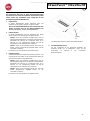 45
45
-
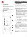 46
46
-
 47
47
-
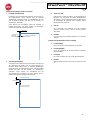 48
48
-
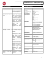 49
49
-
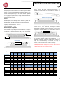 50
50
-
 51
51
-
 52
52
-
 53
53
-
 54
54
-
 55
55
-
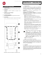 56
56
-
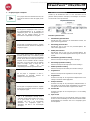 57
57
-
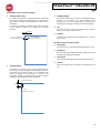 58
58
-
 59
59
-
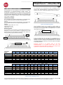 60
60
-
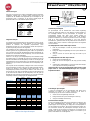 61
61
-
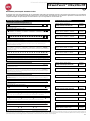 62
62
-
 63
63
-
 64
64
-
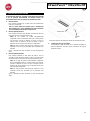 65
65
-
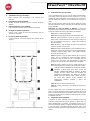 66
66
-
 67
67
-
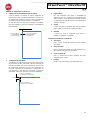 68
68
-
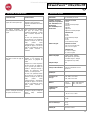 69
69
-
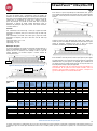 70
70
-
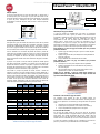 71
71
-
 72
72
-
 73
73
-
 74
74
-
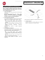 75
75
-
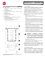 76
76
-
 77
77
-
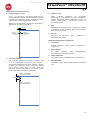 78
78
-
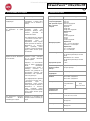 79
79
-
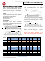 80
80
-
 81
81
-
 82
82
-
 83
83
-
 84
84
-
 85
85
-
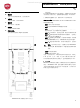 86
86
-
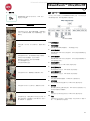 87
87
-
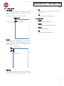 88
88
-
 89
89
-
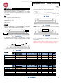 90
90
-
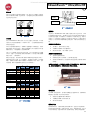 91
91
-
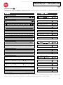 92
92


