Tecnosystemi Compact 2-way digital pressure gauge unit kit, supplied in a carrying case Manuale del proprietario
- Categoria
- Misurazione, test
- Tipo
- Manuale del proprietario

MANUALE D’USO / USER MANUAL
Tecnosystemi S.p.A. - Società Benefit
www.tecnosystemi.com
via dell’Industria, 2/4 - Z.I. San Giacomo di Veglia
31029 Vittorio Veneto (Treviso) - Italy
Phone +39 0438.500044 Fax +39 0438.501516
Numero Verde 800 904474 (only for Italy)
email: [email protected]
C.F. - P. IVA - R.I.TV IT02535780247 | Cap. Soc. € 5.000.000,00 i.v.
REV. 01 / 25-08-2022
COD. CMU00075
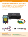
KIT GRUPPO MANOMETRICO DIGITALE
COMPACT 2 VIE, FORNITO IN VALIGETTA
COMPACT 2-WAY DIGITAL PRESSURE GAUGE
UNIT KIT, SUPPLIED IN A CARRYING CASE
• cod. TSC200015

2
DESCRIZIONE
/ DESCRIPTION
Il gruppo manometrico digitale Compact a due vie è uno strumento utile per l’installazione, il test e la
manutenzione degli impianti di refrigerazione, quali ad esempio climatizzatori e gruppi frigo. Lo strumento
dispone di due sensori di pressione, due sonde di temperatura, un display digitale, un selezionatore multi-
unità, una funzione multi-modalità e un database integrato dei refrigeranti.
Lo strumento è realizzato in materiale plastico ad alta resistenza con prese in silicone antiscivolo che
lo rendono solido ed ergonomico. Lo strumento dispone di un microprocessore a 32 bit che permette un’
elevata stabilità e precisione nella ricezione dei dati, di un display LCD retroilluminato di grandi dimensioni che
permette una lettura facile e funzionale. Inoltre dispone di attacchi da ¼ SAE con valvole apri/chiudi di qualità
che garantiscono una buona durata dello strumento.
Lo strumento è in grado di misurare in contemporanea due pressioni e due temperature, con varie unità
di misura settabili facilmente per soddisfare le più diverse esigenze dell’ utilizzatore. Inoltre dispone di
un database integrato con 89 tipi di temperature di evaporazione-pressione refrigerante; calcola anche
il surriscaldamento e il sottoraffreddamento, per facilitare la lettura diretta dei dati di processo operativo.
Inoltre, testa la percentuale di misurazione del vuoto, la misurazione della dispersione di pressione, registra la
velocità del tempo di dispersione.
The Compact two-way digital manifold is a useful tool for the installation, testing and maintenance of refrigeration
systems, such as air conditioners and refrigeration units. The instrument has two pressure sensors, two temperature
probes, a digital display, a multi-unit selector, a multi-mode function and an integrated refrigerant database.
The tool is made of high-strength plastic material with non-slip silicone grips that make it solid and ergonomic. The
instrument has a 32-bit microprocessor that allows high stability and precision in receiving data, a large backlit LCD
display that allows easy and functional reading. It also has ¼ SAE connections with quality open/close valves that
guarantee a good life of the instrument.
The instrument is able to measure two pressures and two temperatures at the same time, with various units of
measurement that can be easily set to meet the most diverse needs of the user. It also has a built-in database with
89 kinds of evaporating temperature-refrigerant pressure; it also calculates superheat and subcooling, to facilitate
direct reading of operational process data. It also tests the percentage of vacuum measurement, pressure leakage
measurement, record the leakage time rate.
PRECAUZIONI E REGOLE DI SICUREZZA
/ PRECAUTIONS AND SAFETY RULES
Questo manuale include le istruzioni per l’utilizzo dello strumento e le avvertenze per un uso nella massima
sicurezza e per la manutenzione idonea. Il diverso utilizzo del gruppo manometrico da quanto previsto sul
manuale può causare danni allo strumento. Questo strumento è rigorosamente conforme alle norme di
sicurezza IEC/EN61010-1 per la progettazione e la produzione.
1) La pressione misurata dal pressostato del gruppo manometrico digitale è la pressione manometrica.
2) Il pressostato rileva da -101Kpa a 6Mpa (da - 0,1 bar a 60 bar).
3) Il pressostato resiste fino a 10 Mpa (100 bar).

3
4) La pressione d’esercizio massima per un flessibile standard è 600 PSI (circa 4.13 Mpa, 41.3 bar). La
pressione limite è 3000 PSI (circa 20.68 Mpa, 206.8 bar).
5) Verificare il valore della pressione nominale dell’apparecchiatura sotto test, prima ancora di svolgere le
prove. Non utilizzare se supera il range dello strumento. Se i flessibili in dotazione non corrispondono ai
requisiti di pressione, è possibile utilizzare altri flessibili con lo stesso attacco
6) Non utilizzare o conservare lo strumento a temperature elevate, in condizioni di umidità elevata, in
presenza di fonti infiammabili o esplosive o in presenza di forti campi elettromagnetici.
7) Non manomettere o sostituire parti dello strumento.
8) Indossare i dispositivi di protezione idonei durante l’ uso dello strumento
9) Utilizzare lo strumento in un ambiente ben ventilato, così da prevenire l’inalazione di gas tossici degli
impianti frigoriferi
La porta è dotata di un tappo a vite in rame. È necessario stringerlo ogni volta, prima o dopo l’utilizzo.
Controllare i tubi e i connettori del sistema di refrigerazione.
This manual includes instructions for using the instrument and warnings for safe use and suitable maintenance.
The different use of the gauge group from what is foreseen in the manual can cause damage to the instrument. This
instrument strictly complies with the safety standards of IEC/EN61010-1 for design and production.
1) The pressure measured by the pressure switch of the digital manifold is the gauge pressure.
2) The pressure switch detects -101Kpa to 6Mpa (-0.1bar to 60bar).
3) The pressure switch resists up to 10 Mpa (100 bar).
4) The maximum working pressure for a standard hose is 600 PSI (approximately 4.13 Mpa, 41.3 bar). The limit
pressure is 3000 PSI (about 20.68 Mpa, 206.8 bar).
5) Check the nominal pressure value of the equipment under test, even before carrying out the tests. Do not use if it
exceeds the range of the instrument. If the supplied hoses do not match the pressure requirements, other hoses with
the same connection can be used
6) Do not use or store the instrument in high temperatures, in conditions of high humidity, in the presence of
flammable or explosive sources or in the presence of strong electromagnetic fields.
7) Do not tamper with or replace parts of the instrument.
8) Wear suitable protective devices when using the instrument
9) Use the instrument in a well-ventilated environment, so as to prevent the inhalation of toxic gases from refrigeration
systems
The port is fitted with a copper screw cap. You need to tighten it every time, before or after use. Check the hoses and
connectors of the refrigeration system.

4
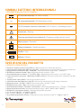
SIMBOLI ELETTRICI INTERNAZIONALI
/ INTERNATIONAL ELECTRICAL SYMBOLS
CC (corrente continua) / DC (direct current)
~CA (corrente alternata) / AC (alternating current)
~CC/ CA (corrente continua + alternata) / DC/ AC (direct + alternating current)
Avvertenza / Warning
Tensione pericolosa (scossa elettrica) / Dangerous voltage (electric shock)
Messa a terra / Grounded
Doppio isolamento / Double insulation
Fusibile / Fuse
Batteria / Battery
+
!
SPECIFICHE DEL PRODOTTO
/ PRODUCT SPECIFICATIONS
• Pressione rilevata: pressione manometrica / Measured pressure: Manometric pressure
• Unità pressione rilevata: Kpa; Mpa; bar; inHg; PSI. / Detected pressure unit: Kpa; Mpa; Cafe; inHg; psi extension.
• Range pressione rilevabile: 0 Kpa – 6000 Kpa / Detectable pressure range: 0 Kpa – 6000 Kpa
• Risoluzione pressione rilevata:1 Kpa / Measured pressure resolution: 1 Kpa
• Accuratezza pressione rilevata: +/- 0.5 %(FS)+ 5dgt / Detected pressure accuracy: +/- 0.5 %(FS)+ 5dgt
• Limite sovraccarico pressione: 10000 Kpa (10 Mpa; 100 bar) / Pressure overload limit: 10000 Kpa (10 Mpa;
100 bar)
• Test del vuoto: vuoto relativo / vacuum test: relative vacuum
• Unità test vuoto: Kpa; Mpa; bar; inHg; PSI / Vacuum test unit: Kpa; Mpa; Cafe; inHg; psi extension
• Range test vuoto: -101 Kpa – 0 Kpa / Vacuum test range: -101 Kpa – 0 Kpa
• Risoluzione test vuoto: 1 Kpa / Vacuum test resolution: 1 Kpa
• Unità temperatura rilevata: °C (Celsius), °F (Fahrenheit) / Measured temperature unit: °C (Celsius), °F (Fahrenheit)
• Range temperatura rilevata / Measured temperature range : -40°C–150°C (-40°F–302°F)
• Risoluzione temperatura rilevata: / Rdetected temperature resolution:
• 0,1°C (-40°C–99.9°C), 1°C (100°C–150°C)
• 0.1°F (-40°F–99.9°F), 1°F (100°F–302°F)
• Accuratezza temperatura rilevata / Temperature accuracy detected: +/- 0,5 °C + 2dgt +/- 0.9 °F +

5
• Database con 89 tipi di refrigerante integrati / Database with 89 integrated refrigerant types
R11 R113 R114 R115 R116 R12 R123 R124 R125 R1270
R13 R134A R14 R141B R142B R143A R152A R170 R21 R218
R22 R227EA R23 R236EA R245CA R245FA R290 R32 R401A R401B
R401C R402A R402B R403A R403B R404A R405A R406A R407A R407B
R407C R407D R407E R408A R409A R409B R41 R410A R410B R411A
R411B R412A R413A R414A R414B R415A R415B R416A R417A R418A
R419A R420A R421A R421B R422A R422B R422C R422D R423A R424A
R425A R426A R427A R428A R50 R500 R501 R502 R503 R504
R507A R508A R508B R509A R600 R600A R717 R744 (CO2) R1234
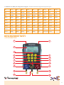
DESCRIZIONE TASTI
/ KEY DESCRIPTION
3
4
5
6
7
8
13
15
17 18
16
14
12
11
10
9
1
2

6
1) Presa sonda temperatura con morsetto
2) Presa sonda temperatura con morsetto
3) Display LCD
4) Tasto avvio/arresto; in modalità test dispersione, tasto di controllo del test
5) Tasto funzione: tasto commutatore modalità di funzione del test
6) Tasti di selezione del tipo di refrigerante r+/r-: commutare per selezionare i diversi tipi di refrige-
ranti da utilizzare
7) Tasto di selezione dell’unità di misura della pressione
8) Temperatura °C/°F: tasto di selezione dell’unità di misura della temperatura
9) Tasto zero: azzera la visualizzazione della pressione
10) Tasto retroilluminazione
11) Tasto di accensione
12) Visore di osservazione del refrigerante
13) Valvola bassa pressione
14) Valvola alta pressione
15) Ingresso bassa pressione ¼ SAE
16) Ingresso alta pressione ¼ SAE
17) Valvola di rilascio pressione
18) Ingresso pompa vuoto/ingresso refrigerante
1) Temperature probe socket with clamp
2) Temperature probe socket with clamp
3) LCD display
4) Start/Stop key; in leakage test mode, test control key
5) Function key: test function mode switch key
6) Refrigerant type selection keys r+/r-: switch to select the different types of refrigerants to be used
7) Pressure unit selection key
8) Temperature °c/°f: key for selecting the temperature unit of measurement
9) Zero key: resets the pressure display
10) Backlight key
11) Power button
12) Refrigerant observation visor
13) Low pressure valve
14) High pressure valve
15) Low pressure inlet ¼ sae
16) High pressure inlet ¼ sae
17) Pressure release valve
18) Vacuum pump inlet/coolant inlet

7
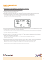
FUNZIONAMENTO
/ OPERATION
A. Chiudere la valvola blu e la valvola rossa.
Close the blue valve and the red valve.
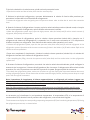
B. Accendere lo strumento. Assicurarsi che il display LCD visualizzi lo stato del test di pressione come
nell’immagine seguente. In caso contrario, premere il tasto Funzione per selezionarlo.
Turn on the instrument. Make sure the LCD displays the pressure test status like the picture
following. If not, press the Function key to select it.
C. Se gli accessori della sonda temperatura sono stati collegati allo strumento, verrà visualizzata la temperatura
in tempo reale. In caso contrario, non verrà visualizzata.
If the temperature probe accessories have been connected to the instrument, the temperature will be displayed
in real time. Otherwise, it will not appear.
D. Premere i tasti R+/ R-, il tasto dell’unità e il tasto °C/°F per selezionare rispettivamente il refrigerante
testato e la visualizzazione della lettura.
Press the R+/ R- keys, the unit key and the °C/°F key to select the refrigerant respectively
tested and display reading.
E. Quando lo strumento è acceso, possono comparire 10 cifre in alto e in basso, nell’area di visualizzazione
della pressione. A questo punto, premere a lungo il tasto zero, fino a che non ritorni a zero.
When the meter is turned on, 10 digits may appear at the top and bottom of the display area
of the pressure. At this point, long press the zero key, until it returns to zero.
1. RIEMPIMENTO DI REFRIGERANTE E ISPEZIONE DELLA PRESSIONE
/ REFRIGERANT FILLING AND PRESSURE INSPECTION

8
2. OPERAZIONI CON IL VUOTO / OPERATIONS WITH VACUUM
A. Chiudere la valvola blu e la valvola rossa./ Close the blue valve and the red valve.
B. Accendere lo strumento. Assicurarsi che il LCD visualizzi lo stato del test del vuoto come nell’immagine
seguente. In caso contrario, premere il tasto Funzione per selezionarlo. / Turn on the instrument. Make sure the
LCD displays the vacuum test status as the following picture. If not, press the Function key to select it.
C. Premere il tasto dell’unità di misura selezionando la desiderata
/ Press the unit of measurement key by selecting the desired one
D. Quando lo strumento è acceso, possono comparire 10 cifre in alto e in basso, nell'area di visualizzazione
della pressione. A questo punto, premere a lungo il tasto zero, fino a che non ritorni a zero.
/ When the meter is turned on, 10 digits may appear at the top and bottom of the pressure display area. At this point,
long press the zero key, until it returns to zero.
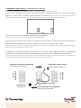
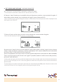
E. Collegare lo strumento al sistema di refrigerazione in base allo schema seguente. (Prestare attenzione alla
direzione del flusso di refrigerante!) (Le sonde di temperatura con morsetto non influenzeranno le operazioni).
/ Connect the instrument to the refrigeration system according to the diagram below. (Pay attention to the direction
of the coolant flow!) (Clamped temperature probes will not affect operations).
Espansione termica valvola
/ Valve thermal expansion
Refrigera/ Refrigerate
Compressore
/ Compressor Direzione del flusso di refrigerante
/ Direction of coolant flow
Direzione del flusso di refrigerante
/ Direction of coolant flow
Evaporatore
/ Evaporator
Condensatore
/ Condenser

9
F. Aprire la valvola blu e la valvola rossa, quindi avviare la pompa del vuoto
/ Open the blue valve and the red valve, then start the vacuum pump
G. Attivare la valvola del refrigerante e premere delicatamente la valvola di rilascio della pressione per
permettere lo sfiato dell’aria nel flessibile di collegamento.
/ Activate the refrigerant valve and gently press the pressure release valve to allow the air vent in the connection
hose.
H. Quando il sistema di refrigerazione si arresta, aprire la valvola ad alta pressione (valvola rossa) e riempire
con una certa quantità di refrigerante, quindi chiudere velocemente la valvola.
/ When the refrigeration system stops, open the high pressure valve (red valve) and fill with a certain amount of
refrigerant, then quickly close the valve.
I. Attivare il sistema di refrigerazione, aprire la valvola a bassa pressione (valvola blu) e riempire con il
refrigerante nel sistema di refrigerazione. Le operazioni con il vuoto sono necessarie se c’è il riempimento
iniziale o completo con refrigerante. Fare riferimento alla sezione sulle operazioni con il vuoto.
/ Activate the refrigeration system, open the low pressure valve (blue valve) and fill with the refrigerant in the
refrigeration system. Operations with vacuum are necessary if there is the initial or full fill with coolant. Refer to the
section on vacuum operations.
J. Dopo aver completato il riempimento, chiudere la valvola a bassa pressione (valvola blu) e la valvola del
refrigerante. Lasciare che il sistema di refrigerazione si avvii.
/ After completing the filling, close the low pressure valve (valve blue) and the coolant valve. Let the refrigeration
system start.
K. Arrestare il sistema di refrigerazione, accertarsi che tutte le valvole siano disattivate, quindi scollegare lo
strumento tra la sorgente e il sistema di refrigerazione. Non rimuovere il collegamento della valvola ad alta
pressione, fino a che la pressione non cala fino al punto di sicurezza. Spegnere quindi lo strumento.
/ Shut down the refrigeration system, make sure all valves are off, then unplug the instrument between the source
and the refrigeration system. Do not remove the ad valve connection high pressure, until the pressure drops to a safe
point. Then turn off the instrument.
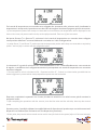
Lo strumento può visualizzare la corrispondente temperatura di evaporazione (EV) e la temperatura di
condensazione (CO) durante il test di pressione del refrigerante, come mostrato di seguito:
Nota: L’operazione di riempimento di diverse apparecchiature o refrigeranti può variare. Leggere con
attenzione i requisiti specifici di utilizzo per le operazioni di riempimento, così da evitare danni all’utente o
all’apparecchiatura causato da un utilizzo non corretto.
Note: The filling operation of different equipment or refrigerants may vary. Carefully read the specific usage
requirements for filling operations, so as to avoid damage to the user or the equipment caused by incorrect use.
The instrument can display the corresponding evaporating temperature (EV) and condensing temperature (CO) during
the refrigerant pressure test, as shown below:

10
Se le sonde di temperatura con morsetto sono collegate allo strumento,nello schermo verrà visualizzata la
temperatura in tempo reale, la pressione non calerà fino alla soglia di sicurezza. Spegnere quindi lo strumento.
/ If the temperature probes with clamp are connected to the instrument, the temperature will be displayed in real
time on the screen, the pressure will not drop to the safety threshold. Then turn off the instrument.
Nel punto Sensore T1 e Sensore T2, assicurarsi che le sonde di temperatura con morsetto siano collegate
come previsto dalla fase F e messe totalmente a contatto con i tubi di refrigerazione
/ In point Sensor T1 and Sensor T2, make sure that the temperature probes with clamp are connected as required by
phase F and are fully in contact with the refrigeration pipes
Lo strumento è in grado di calcolare il SH - Surriscaldamento e il SC - Sottoraffreddamento, come mostrato
di seguito, a condizione che il refrigerante testato sia preimpostato e le sonde di temperatura con morsetto
siano ben collegate.
/ The instrument is able to calculate the SH - Superheat and the SC - Subcool, as shown below, provided that the
tested refrigerant is preset and the clamp temperature probes are well connected.
Dopo aver completato le operazioni con il vuoto, chiudere la valvola blu e la valvola rossa, quindi arrestare la
pompa del vuoto.
/ After completing the operations with the vacuum, close the blue valve and the red valve, then stop the vacuum
pump.
A questo punto, è possibile utilizzare la modalità del test di dispersione di pressione per controllare eventuali
dispersioni nel sistema (fare riferimento a 3 Test dispersione pressione).
/ At this point, the pressure leak test mode can be used to check for leaks in the system (refer to 3 Pressure leak test).

11
A. Lo strumento è acceso quando le valvole blu e rossa sono chiuse.
/ The instrument is switched on when the blue and red valves are closed.
B. Premere il tasto Funzione per la modalità del test di dispersione pressione, come mostrato di seguito. Il
valore della pressione attuale viene visualizzato sull’angolo in basso a destra del LCD.
/ Press Function key for pressure leakage test mode, as shown below. The current pressure value is displayed on the
lower right corner of the LCD.
C. Premere il tasto avvio/arresto per avviare il test di dispersione, come mostrato di seguito:
/ Press the start/stop key to start the leak test, as shown below:
A questo punto, l’angolo in basso a sinistra registra il valore della pressione iniziale; l’angolo in basso a destra
mostra il valore di pressione istantaneo; l’area di visualizzazione “ΔP” mostra la differenza tra il valore della
pressione iniziale e il valore della pressione istantanea.
L’area di visualizzazione del tempo mostra la durata del test di dispersione nel formato Ore: Minuti (HH:MM).
Tutte le unità di pressione sullo schermo sono uguali. È possibile cambiare l’unità di misura della pressione,
premendo il tasto dell’unità.
3. TEST DISPERSIONE PRESSIONE / PRESSURE LEAKAGE TEST
/ At this point, the lower left corner records the initial pressure value; the lower right corner shows the instantaneous
pressure value; the display area “ΔP” shows the difference between the initial pressure value and the instantaneous
pressure value.
The time display area shows the duration of the leak test in Hours:Minutes (HH:MM) format. All pressure units on the
screen are the same. You can change the pressure unit by pressing the unit key.

12
Sullo strumento si attiva il segnale di alimentazione scarsa. Quando viene visualizzato, vuol dire che
l’alimentazione della batteria è insufficiente. A questo punto, la batteria deve essere sostituita per evitare
problemi sul normale utilizzo.
Controllare i raccordi delle tubature e i flessibili prima di effettuare il test. Una volta rilevato il danno, sostituire
immediatamente per evitare usi impropri o possibili incidenti.
È presente una valvola a saracinesca sull’ingresso per il refrigerante del sistema di refrigerazione. Quando lo
strumento viene collegato, prestare attenzione ai due terminali dei flessibili. Collegare un terminale con una
valvola al sistema di refrigerazione, mentre l’altro terminale senza una valvola allo strumento.
-Ogni terminale del flessibile è dotato di un pad di nylon che ha una vita utile limitata. Il sovrautilizzo o altre
situazioni potrebbero renderlo difettoso, causando quindi dispersioni.
-L’ingresso per il refrigerante dello strumento (la porta intermedia dello strumento) è dotato di una porta con
valvola a saracinesca, utilizzata per lo sfiato dell’aria nei flessibili dopo il collegamento del refrigerante allo
strumento.
La porta è dotata di un tappo a vite in rame. È necessario stringerlo ogni volta, prima o dopo l’utilizzo.
- Controllare i tubi e i connettori del sistema di refrigerazione.
1. BATTERIA SCARICA / LOW BATTERY
2. STELO VALVOLA O FLESSIBILE DEL REFRIGERANTE DANNEGGIATO
/ DAMAGED VALVE STEM OR REFRIGERANT HOSE
3. PROBLEMI NEL RIEMPIMENTO DEL REFRIGERANTE
/ PROBLEMS FILLING THE COOLANT
4. PUNTI POTENZIALI DI DISPERSIONE
/ POTENTIAL POINTS OF DISPERSION
PROBLEMI COMUNI
/ COMMON PROBLEMS
/ The low power signal activates on the instrument. When it is displayed, it means that the battery power is low. At
this point, the battery needs to be replaced to avoid problems on normal use.
/ Check pipe fittings and hoses before testing. Once damage is found, replace immediately to avoid misuse or possible
accidents.
/ There is a gate valve on the refrigerant inlet of the refrigeration system. When connecting the tool, pay attention to
the two hose ends. Connect one terminal with a valve to the refrigeration system and the other terminal without a
valve to the instrument.
/ -Each hose terminal is equipped with a nylon pad that has a limited life. Overuse or other situations may make it
defective, thus causing leakage.
-The tool coolant inlet (the middle port of the tool) has a gate valve port, used to vent air in the hoses after the coolant
is connected to the tool.

13
The port is fitted with a copper screw cap. You need to tighten it every time, before or after use.
- Check the pipes and connectors of the refrigeration system.
GLOSSARIO
/ GLOSSARY
SATURAZIONE / SATURATION
Lo stato della saturazione è la coesistenza di un refrigerante in stato liquido e gassoso.
/ The state of saturation is the coexistence of a refrigerant in liquid and gaseous state.
TEMPERATURA DI CONDENSAZIONE E TEMPERATURA DI EVAPORAZIO
/ CONDENSING TEMPERATURE AND EVAPORATING TEMPERATURE
Temperatura di condensazione: nel condensatore, il refrigerante viene condensato dal refrigerante gassoso
ad alta temperatura, alla temperatura del refrigerante liquido, ossia alla temperatura di saturazione sotto
pressione condensante.
Temperatura di evaporazione: nell’evaporatore, il refrigerante evapora dal refrigerante liquido alla temperatura
del refrigerante gassoso, ossia alla temperatura di saturazione sotto pressione di evaporazione.
/ Condensing temperature: In the condenser, the refrigerant is condensed from the gaseous refrigerant at a high
temperature, at the temperature of the liquid refrigerant, i.e. at the saturation temperature under condensing pressure.
Evaporating temperature: In the evaporator, the refrigerant evaporates from the liquid refrigerant at the temperature
of the gaseous refrigerant, i.e. the saturation temperature under evaporating pressure.
GRADO DI SOTTORAFFREDDAMENTO E SURRISCALDAMENTO
/ DEGREE OF SUBCOOLING AND SUPERHEATING
Sottoraffreddamento: temperatura di condensa - temperatura di uscita della condensa.
/ Subcooling: Condensation temperature - Condensate outlet temperature.
Surriscaldamento; temperatura di uscita dell’evaporazione - temperatura di evaporazione.
/ Overheating; evaporating outlet temperature - evaporating temperature.
Il sottoraffreddamento più basso può migliorare la capacità di refrigerazione del sistema. Aggiungere il circuito
di sottoraffreddamento e l’economizzatore nel sistema di refrigerazione per aumentare il sottoraffreddamento
per il refrigerante in aumento.
Il grado di espansione della valvola d’espansione (caricamento refrigerante) influenza il grado di
surriscaldamento. Maggiore è il grado di surriscaldamento, minore è l’apertura della valvola di apertura
determinabile (la carica di refrigerante è inferiore).
/ Lower subcooling can improve the refrigeration capacity of the system. Add the subcooling loop and economizer into
the refrigeration system to increase the subcooling for the rising refrigerant.
The degree of expansion of the expansion valve (refrigerant charge) influences the degree of superheating. The higher
the degree of superheating, the smaller the opening of the opening valve can be determined (refrigerant charge is
lower).

14
CALORE SENSIBILE E CALORE LATENTE
/ SENSIBLE HEAT AND LATENT HEAT
La quantità di calore richiesto per innalzare la temperatura dell’acqua da 0 gradi a 100 gradi è il calore sensibile,
l’acqua viene riscaldata a 100 gradi, mentre l’acqua bollente diventa vapore acqueo, ma la temperatura è
ancora di 100 gradi. Il calore richiesto per questo processo viene denominato calore latente.
/ The amount of heat required to raise the temperature of water from 0 degrees to 100 degrees is sensible heat,
water is heated to 100 degrees, while boiling water becomes water vapor, but the temperature is still 100 degrees .
The heat required for this process is called latent heat.
PRESSIONE MANOMETRICA E PRESSIONE ASSOLUTA
/ GAUGE PRESSURE AND ABSOLUTE PRESSURE
Pressione manometrica: Per pressione manometrica si intende la pressione della tubatura, si riferisce alla
pressione misurata dai manometri, dai misuratori del vuoto, dai tubi a U ecc. È detta anche pressione relativa.
La “pressione da grafico” inizia con la pressione atmosferica e il simbolo è Pg.
/ Manometric pressure: Manometric pressure means the pressure of the pipeline, it refers to the pressure measured
by pressure gauges, vacuum gauges, U-tubes, etc. It is also called relative pressure. The “graph pressure” starts with
atmospheric pressure and the symbol is Pg.
PRESSIONE ASSOLUTA
/ ABSOLUTE PRESSURE
La pressione che agisce direttamente sulla superficie di un contenitore o di un oggetto viene chiamata “pres-
sione assoluta”; il valore della pressione assoluta è il vuoto assoluto come punto di partenza, il simbolo è
PABS (ABS è un subscript) e la pressione assoluta è data dalla pressione atmosferica + pressione manome-
trica. A pressione atmosferica, la pressione manometrica è 0 e la pressione assoluta è 1.013 bar. Temperatu-
ra bulbo secco, temperatura bulbo umido e temperatura sfera nera
/ The pressure that acts directly on the surface of a container or object is called “absolute pressure”; the absolute
pressure value is absolute vacuum as a starting point, the symbol is PABS (ABS is a subscript), and the absolute
pressure is atmospheric pressure + gauge pressure. At atmospheric pressure, gauge pressure is 0 and absolute
pressure is 1.013 bar. Dry bulb temperature, wet bulb temperature and black sphere temperature
Temperatura bulbo secco: temperatura misurata dai termometri ordinari.
Temperatura bulbo umido: un panno umido viene posizionato attorno al termometro; la temperatura indica
un calo dovuto all’evaporazione dell’acqua. A questo punto, la temperatura viene chiamata temperatura di
bulbo umido.
/ Dry bulb temperature: temperature measured by ordinary thermometers.
Wet bulb temperature: a damp cloth is placed around the thermometer; the temperature indicates a decrease due to
the evaporation of the water. At this point, the temperature is called the wet bulb temperature.
Il dispositivo, dotato sia di termometro a sfere a secco sia di termometro a bulbo umido, viene chiamato
umidimetro a secco e può essere utilizzato per misurare l’umidità relativa in atmosfera.
Temperatura della sfera nera: denominata anche temperatura effettiva, indica la temperatura effettiva del
sensore espressa dalla temperatura, quando una persona o un oggetto è abbinato al calore radiante e al calore
convettivo in un ambiente a calore radiante.
La temperatura della sfera nera misurata è generalmente superiore rispetto alla temperatura ambiente, che
è la temperatura dell’aria.

15
/The device, equipped with both a dry ball thermometer and a wet bulb thermometer, is called a dry humidometer
and can be used to measure the relative humidity in the atmosphere.
Black Ball Temperature: Also called effective temperature, this is the actual sensor temperature expressed by
temperature, when a person or object is combined with radiant heat and convective heat in a radiant heat environment.
The temperature of the measured black ball is usually higher than the ambient temperature, which is the air
temperature.
UMIDITÀ RELATIVA E UMIDITÀ ASSOLUTA
/ RELATIVE HUMIDITY AND ABSOLUTE HUMIDITY
Umidità assoluta: la massa di vapore acqueo in un volume unitario di aria viene chiamata “umidità assoluta”
dell’aria. È una rappresentazione della quantità fisica dell’umidità e della secchezza atmosferica. Viene
generalmente espressa in grammi di vapore acqueo contenuti in 1 metro cubo di aria.
Umidità relativa: la densità effettiva del vapore acqueo nell’aria e la densità percentuale del vapore acqueo
saturato alla stessa temperatura sono denominate “umidità relativa” dell’aria.
Il grado di secchezza e umidità dell’aria è correlato al grado di saturazione del vapore acqueo contenuto
nell’aria, ma non è direttamente correlato alla quantità assoluta di vapore acqueo contenuto nell’aria.
/ Absolute humidity: The mass of water vapor in a unit volume of air is called the “absolute humidity” of the air. It is
a representation of the physical amount of atmospheric moisture and dryness. It is generally expressed in grams of
water vapor contained in 1 cubic meter of air.
Relative humidity: The actual density of water vapor in the air and the percentage density of saturated water vapor
at the same temperature are called the “relative humidity” of the air.
The degree of dryness and humidity of the air is related to the degree of saturation of the water vapor contained in
the air, but it is not directly related to the absolute amount of water vapor contained in the air.
COP E EER
/ COP AND EER
EER: il rapporto tra capacità di raffreddamento e potenza d’ingresso effettiva, quando il condizionatore
dell’aria effettua l’operazione di raffreddamento alle condizioni nominali e alle condizioni specificate, il cui
valore viene espresso in W/W.
COP: in condizioni operative nominali (temperatura elevata) e in condizioni specifiche, durante il funzionamento
di riscaldamento della pompa di calore dell’aria condizionata, il rapporto tra potenza in ingresso effettiva e il
riscaldamento, il cui valore viene espresso in W/W.
/EER: The ratio of cooling capacity to effective input power, when the air conditioner performs cooling operation
under the rated conditions and specified conditions, the value of which is expressed in W/W.
COP: under nominal operating conditions (high temperature) and under specific conditions, during heating operation
of the air conditioning heat pump, the ratio between actual input power and heating, the value of which is expressed
in W/W.

SMALTIMENTO
DISPOSAL
GARANZIA
WARRANTY
Alla fine della sua vita utile il prodotto non deve essere smaltito insieme ai rifiuti urbani. Può essere
consegnato presso gli appositi centri di raccolta differenziata predisposti dalle amministrazioni
comunali, oppure presso i rivenditori che forniscono questo servizio. Per rimarcare l’obbligo di smaltire
separatamente gli elettrodomestici, sul prodotto è riportato il marchio del contenitore di spazzatura
mobile barrato.
At the end of its useful life, the product must not be disposed of with household waste. It can be deposited at
a dedicated recycling centre run by local councils, or at retailers who provide such a service. To highlight the
requirement to dispose of household electrical items separately, there is a crossed-out waste paper basket
symbol on the product.
La garanzia ha durata di 1 (uno) anno a decorrere dalla data di consegna indicata sul d.d.t (bolla). E’ prevista altresì
l’estensione d’ufficio, a titolo gratuito, per il secondo anno (due anni complessivi di garanzia) con decorrenza sempre
dalla data indicata nel d.d.t di consegna (bolla).
L’azienda fornitrice garantisce la qualità dei materiali impiegati e la corretta realizzazione dei componenti. La garanzia
copre difetti di materiale e di fabbricazione e si intende relativa alla fornitura dei pezzi in sostituzione di qualsiasi
componente che presenti difetti, senza che possa venir reclamata alcuna indennità, interesse o richiesta di danni.
La garanzia non copre la sostituzione dei componenti che risultano danneggiati per:
• trasporto non idoneo;
• installazione non conforme a quanto specificato in questo manuale di installazione uso e manutenzione;
• la non osservanza delle specifiche tecniche di prodotto;
• quant’altro non riconducibile a vizi originari del materiale o di produzione a condizione che il reclamo del cliente
sia coperto dalla garanzia e notificato nei termini e modalità richiesta dal fornitore, lo stesso si impegnerà, a sua
discrezione, a sostituire o riparare ciascun prodotto o le parti di questo che presentino vizi o difetti.
The warranty is valid for 2 (two) years from the delivery date indicated on the delivery note / waybill.
The supplier company guarantees the quality of the materials used and the correct construction of the components. The
warranty covers defects in materials and manufacturing defects and refers to the supply of spare parts of any components
featuring defects, without any compensation, interest or claim for damages.
The warranty does not cover the replacement of components damaged due to:
incorrect transportation;
installation not compliant with that specified in this installation, use and maintenance manual;
non-observance of product technical specifications;
Anything else that is not linked to original faults of the material or production provided that the customer complaint is covered
by the guarantee and a claim is made within the time limit and in the way requested by the supplier, the same supplier will
commit, at their own discretion, to replace or repair any product or part of product showing signs of faults or defects.
Tecnosystemi S.p.A. Società Benefit
www.tecnosystemi.com
via dell’Industria, 2/4 - Z.I. San Giacomo di Veglia
31029 Vittorio Veneto (Treviso) - Italy
Phone +39 0438.500044 | Fax +39 0438.501516
email: [email protected]
C.F. - P. IVA - R.I.TV IT02535780247
Cap. Soc. € 5.000.000,00 i.v.
W
E
A
R
E
A
B
E
N
E
F
I
T
C
O
M
P
A
N
Y
WATCH OUR
INSTITUTIONAL VIDEO
II
SS
OO
9
9
0
0
0
0
1
1
S
S
Y
Y
S
S
T
T
E
E
MM
CC
EE
RR
TT
II
FF
II
C
C
A
A
T
T
I
I
O
O
N
N
800 904474
ONLY FOR ITALY
-
 1
1
-
 2
2
-
 3
3
-
 4
4
-
 5
5
-
 6
6
-
 7
7
-
 8
8
-
 9
9
-
 10
10
-
 11
11
-
 12
12
-
 13
13
-
 14
14
-
 15
15
-
 16
16


Tecnosystemi Compact 2-way digital pressure gauge unit kit, supplied in a carrying case Manuale del proprietario
- Categoria
- Misurazione, test
- Tipo
- Manuale del proprietario
in altre lingue
Documenti correlati
-
Tecnosystemi 4-way dry gauge unit Manuale del proprietario
-
-
-
-
-
-
-
-
-
Altri documenti
-
MasterCool R11 Manuale utente
-
 Refco WIRELESS-CLAMP WTC Manuale utente
-
 Olimpia Splendid Sherpa Manuale del proprietario
-
Trane Jupiter JUAV Series Installation Operation & Maintenance
-
-
-
-
Carrier AQUASNAP 30RH 026 Guida utente
-
MasterCool 52246 Manuale utente

