
COSTA DI
SICUREZZA

ITALIANO
AVVERTENZE PER L’INSTALLATORE
OBBLIGHI GENERALI PER LA SICUREZZA
ATTENZIONE! È importante per la sicurezza delle persone seguire attentamente tutta l’istruzione. Una errata installazione o un errato uso del prodotto
può portare a gravi danni alle persone.
Leggere attentamente le istruzioni prima di iniziare l’installazione del prodotto.
I materiali dell’imballaggio (plastica, polistirolo, ecc.) non devono essere lasciati alla portata dei bambini in quanto potenziali fonti di pericolo.
Conservare le istruzioni per riferimenti futuri.
Questo prodotto è stato progettato e costruito esclusivamente per l’utilizzo indicato in questa documentazione. Qualsiasi altro utilizzo non espressamente indicato potrebbe
pregiudicare l’integrità del prodotto e/o rappresentare fonte di pericolo.
Non installare l’apparecchio in atmosfera esplosiva: la presenza di gas o fumi infiammabili costituisce un grave pericolo per la sicurezza.
GENIUS declina ogni responsabilità ai fini della sicurezza e del buon funzionamento dell’automazione, in caso vengano utilizzati componenti dell’impianto non di produzione
GENIUS.
Per la manutenzione utilizzare esclusivamente parti originali GENIUS.
L’utente utilizzatore deve astenersi da qualsiasi tentativo di riparazione o d’intervento e deve rivolgersi solo ed esclusivamente a personale qualificato GENIUS o centri d’assi-
stenza GENIUS.
La costa di sicurezza NON deve essere utilizzata come dispositivo di normale arresto o di arresto d’emergenza di porte o cancelli motorizzati.
La costa di sucurezza se utilizzata in queste applicazioni non ne garantisce la sicurezza:
chiuse e paratie
porte di ascensori
porte di veicoli
porte blindate
porte utilizzate principalmente per trattenere animali
sipari teatrali in tessuto
barriere ferroviarie
barriere utilizzate esclusivamente per veicoli
La costa di sicurezza NON deve essere utilizzata come arresto di emergenza di macchine operatrici
La costa di sicurezza NON garantisce la corretta funzionalità se installata in ambienti con livelli di inquinamento elettromagnetico superiore a quello specificato nella norma EN
61000-6-4 o EN 55014-2 quando montato su porte da garage al uso domestico.
Tutto quello che non è previsto espressamente in queste istruzioni non è permesso.
ENGLISH
IMPORTANT NOTICE FOR THE INSTALLER
GENERAL SAFETY REGULATIONS
ATTENTION! To ensure the safety of people, it is important that you read all the following instructions. Incorrect installation or incorrect use of the product
could cause serious harm to people.
Carefully read the instructions before beginning to install the product.
Do not leave packing materials (plastic, polystyrene, etc.) within reach of children as such materials are potential sources of danger.
Store these instructions for future reference.
This product was designed and built strictly for the use indicated in this documentation. Any other use, not expressly indicated here, could compromise the good condition/ope-
ration of the product and/or be a source of danger.
Do not install the equipment in an explosive atmosphere: the presence of inflammable gas or fumes is a serious danger to safety.
GENIUS declines all liability as concerns safety and efficient operation of the automated system, if system components not produced by GENIUS are used.
For maintenance, strictly use original parts by GENIUS.
The User must not in any way attempt to repair or to take direct action and must solely contact qualified GENIUS personnel or GENIUS service centres.
The MSE110W safety edge must NOT be used as a normal stopping device or emergency stop for motor-driven doors or gates.
If the MSE110W safety edge is used in the following applications, it does NOT guarantee their safety:
sluices and bulkheads.
lift doors.
vehicle doors.
armoured doors.
doors mainly used for restraining animals.
theatre curtains in fabric.
railway barriers.
barriers used exclusively for vehicles.
The MSE110W safety edge must NOT be used as an emergency stop for operating machines.
The MSE110W safety edge does NOT guarantee correct operation if it is installed in places with a level of electromagnetic pollution higher than that specified in standard EN
61000-6-4 or EN 55014-2 when installed on garage doors for domestic use.
Anything not expressly specified in these instructions is not permitted.
FRANÇAIS
CONSIGNES POUR L’INSTALLATEUR
RÈGLES DE SÉCURITÉ
ATTENTION! Il est important, pour la sécurité des personnes, de suivre à la lettre toutes les instructions. Une installation erronée ou un usage erroné du
produit peut entraîner de graves conséquences pour les personnes.
Lire attentivement les instructions avant d’installer le produit.
Les matériaux d’emballage (matière plastique, polystyrène, etc.) ne doivent pas être laissés à la portée des enfants car ils constituent des sources potentielles de danger.
Conserver les instructions pour les références futures.
Ce produit a été conçu et construit exclusivement pour l’usage indiqué dans cette documentation. Toute autre utilisation non expressément indiquée pourrait compromettre
l’intégrité du produit et/ou représenter une source de danger.
Ne pas installer l’appareil dans une atmosphère explosive: la présence de gaz ou de fumées inflammables constitue un grave danger pour la sécurité.
GENIUS décline toute responsabilité quant à la sécurité et au bon fonctionnement de l’automatisme si les composants utilisés dans l’installation n’appartiennent pas à la
production GENIUS.
Utiliser exclusivement, pour l’entretien, des pièces GENIUS originales.
L’utilisateur doit s’abstenir de toute tentative de réparation ou d’intervention et doit s’adresser uniquement et exclusivement au personnel qualifié GENIUS ou aux centres
d’assistance GENIUS.
Le bord de sécurité MSE110W NE doit PAS être utilisé comme un dispositif d’arrêt normal ou d’arrêt d’urgence pour portes ou portails motorisés.
Sur les applications suivantes, le bord de sécurité MSE110W N’en garantit PAS la sécurité:
écluses et parois.
portes d’ascenseurs.
portes de véhicules.
portes blindées.
portes principalement utilisées pour retenir des animaux.
rideaux de scène en tissu.
barrières ferroviaires.
barrières exclusivement utilisées pour les véhicules.
Le bord de sécurité MSE110W NE doit PAS être utilisé comme un dispositif d’arrêt d’urgence pour engins de chantier.
Le bord de sécurité MSE110W NE garantit PAS un fonctionnement correct s’il est installé dans des endroits où le niveau de pollution électromagnétique est supérieur au niveau
spécifié dans la norme EN 61000-6-4 ou EN 55014-2 lorsqu’il est monté sur des portes de garage à usage domestique.
Tout ce qui n’est pas prévu expressément dans ces instructions est interdit.
1.
2.
3.
4.
5.
6.
7.
8.
9.
10.
•
•
•
•
•
•
•
•
11.
12.
13.
1.
2.
3.
4.
5.
6.
7.
8.
9.
10.
•
•
•
•
•
•
•
•
11.
12.
13.
1.
2.
3.
4.
5.
6.
7.
8.
9.
10.
•
•
•
•
•
•
•
•
11.
12.
13.

11
ENGLISH
CE DECLARATION OF CONFORMITY
ENCLOSURE II - part C - Machines Directive
Notes on reading the instruction
Read this installation manual to the full before you begin installing the product.
The symbol indicates notes that are important for the safety of persons and for the good condition of the
automated system.
The symbol draws your attention to the notes on the characteristics and operation of the product.
Manufacturer: GENIUS S.p.A.
Address: Via Padre Elzi, 32 - 24050 - Grassobbio- Bergamo - ITALY
Declares that: The opto-electronic active protection device
• conforms to the essential safety requirements of the following EEC directives:
EN 12978 - Category 2
73/23/EEC and subsequent amendment 93/68/EEC.
89/336/EEC and subsequent amendment 92/31/EEC and 93/68/EEC
Additional information:
This product underwent a test in a typical uniform configuration (all products manufactured by GENIUS S.p.A.).
Grassobbio, 01-06-2006
Managing Director
D. Gianantoni
INDEX
1 DESCRIPTION AND TECHNICAL SPECIFICATIONS page.12
2 DIMENSIONS page.1
2
3 OPERATION page.1
3
4 ACCESSORIES page.1
3
5 INSTALLING THE DEVICE page.1
3
5.1 TYPES OF INSTALLATION page.1
3
5.2 POSITIONING AND SIZING THE COMPONENTS page.1
4
5.3 INSTALLATION SEQUENCE page.1
4
6 ELECTRICAL CONNECTIONS page.1
6
7 OPERATING DIAGNOSTICS page.1
6
8 FINAL OPERATIONS page.1
7
9 REPLACING THE BATTERIES page.1
7
9.1 TOP AND BOTTOM TRANSMITTER page.1
7
9.2 RECEIVER-TRANSMITTER page.1
7
10 MANUTENZIONE page.1
7
11 IDENTIFICATION OF THE SYSTEM page.1
7
12 INSTALLATION OF FIXED RECEIVER ON VEGA COLUMN page.1
8

12
Dimension in mm
ENGLISH
SAFETY EDGE
1 DESCRIPTION AND TECHNICAL
SPECIFICATIONS
These instructions are valid for the GENIUS Safety Optical
Edge.
The saety optical edge is a safety device conforming to
European Standard EN 12978 category 2, and can be
installed ONLY for protecting the primary edge (opening
or closing) of the mobile leaf of a sliding gate.
Furthermore, it simultaneously performs the functions of a
photocell (EN 12453 C + D).
Inoltre svolge contemporaneamente la funzione di foto-
cellula (EN 12453 C + D).
For installation and operation, scrupulously adhere
to these instructions. Do not use them for any
other purpose.
Carefully read the GENERAL WARNINGS.
To avoid possible interference, do NOT use photo-
cells on sliding gates where the safety edge is to
be installed.
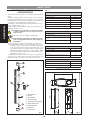
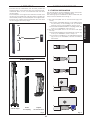
The safety adge consists of a mobile and a fixed part:
•The mobile part includes two emitting units (Fig. 1 ref. c
and g) located at the ends of a rubber profile (Fig.
1 ref. d and f) and a receiver-transmitter (Fig. 1 ref.
e) located in an intermediate position. All these units
operate on lithium batteries mod. AA - L91 - 1,5V.
The rubber profile is sustained by a special support in
aluminium (Fig. 1 ref. a).
•The fixed part consists of a receiver (Fig. 1 ref. i) whose
function is to communicate with the equipment and to
signal (with LEDs) the state of the device to the user.
1
2
3
4
5
6
7
8
9
TAB. 1
Safety Edge
Operating ambient temperature (°C) -20 ÷ +55
Protection class (IP) 55
Sensitive edge detection time (msec) 30
Photocell detection time (msec) 90
Edge maximum height (m) 2.5
Maximum width of the passage (m) 15
Certification EN12978 cat.2
TAB. 2
MOBILE TRANSMITTER - c and g
Lithium batteries power supply 2x1.5V AA LG91
Time range (years) ~3
Remaining operating time following batt. signal
(months)
2
Maximum distance from receiver/transmitter
(m)
2.5
TAB. 3
MOBILE RECEIVER-TRANSMITTER - e
Lithium batteries power supply 2x1.5V AA LG91
Time range (years) ~3
Remaining operating time following batt. signal
(months)
2
Maximum distance from fixed receiver (m) 15
TAB. 4
FIXED RECEIVER - i
Power supply (Vdc) 24
Type of output contacts 1 N.C.
Range of 24 Vdc (A) contact 1
2 DIMENSIONS
135.5
4324
42.5
135
35
a
Support profile
b
Top cap
c
Top transmitter
d
Top rubber profile
e
Central receiver-transmitter
f
Bottom rubber profile
g
Bottom transmitter
h
Bottom cap
i
Fixed receiver
Fig. 1 Fig. 2

13
ENGLISH
3 OPERATION
The infra-red ray transmitters (TX1 and TX2), inside the
sensitive edge, communicate with the central receiver-
transmitter which, in turn, communicates with the fixed
receiver (RX3).
The interruption of the light beam between emitter and
receiver on the mobile part (following impact against the
deformable profile) or the interruption of the light beam
between the mobile receiver-transmitter and the fixed
receiver triggers the safety edge.
TX1
RX1
RX2
TX2
TX3
RX3
4 ACCESSORIES
5 INSTALLING THE DEVICE
5.1 TYPES OF INSTALLATION
The fixed receiver can be installed by using various solu-
tions, according to the type of sliding gate.
The following types of installations can be made with the
help of the accessories shown in Fig. 3:
1) The gate and pillar are on the same axis (Fig.4 ref.
A-B-C):
• the receiver is installed directly on the pillar without
any accessory, on the wall (Fig. 4 ref. A) or embed-
ded (Fig. 4 ref. B). For installation, see par. 5.3.4.
• the receiver is installed inside the coupling profile (Fig.
4 ref. C). For installation, see par. 5.3.5.
2) The gate and pillar are not on the same axis (Fig.4
ref. D-E):
• the receiver is installed on the Safe Beam column (fig.
4 ref. D). For installation, refer to Chap. 12.
• the receiver is installed on the adjustable support
(Fig. 4 ref. E). For installation, see the accessory’s
instructions.
Column Vega
Profile
for coupling
Support
for fixed receiver
Fig. 3 Fig. 4

14
ENGLISH
5.2 POSITIONING AND SIZING THE COM-
PONENTS
When you have chosen the type of installation for the fixed
receiver, size the components as described below.
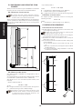
5.2.1 Positioning the fixeD receiver
To ensure that the system operates correctly,
take great care in aligning the lenses of the fixed
receiver and of the receiver-transmitter.
When the fixed receiver is not installed on the Safe Beam
column, position it so that the lens on the front panel (Fig.
8 ref. a) is at a height HT from 50 to 55 cm off the ground
(HT see Fig. 5).
XX
T
HT
LS
L1
L2
5.2.2 sizing the rubber Profiles
The rubber profile is supplied as a single piece, with a
length of 2.5 m.
To correctly size the top and bottom rubber profiles, use the
formulas below (all dimensions are in millimeters).
We advise you to cut the rubber profile cleanly and
precisely.
• Bottom rubber profile L2:
L2 = HT - T - 63,5
where:
HT = Height between lens of fixed receiver and ground.
T = Distance from ground to finished edge.
Dimension T must not be less than 40 mm. If this
dimension were smaller, it would be impossible
to install the bottom cap and, therefore, the
installation would be incomplete.
• Top rubber profile L1:
L1 = X + T - HT - 63,5
where:
X = Total length of finished edge (max. 2500mm)
T = Distance from ground to finished edge.
HT = Height between lens of fixed receiver and ground.
5.2.3 sizing the suPPort Profile
The support profile in aluminium must be cut using the
following formula:
LS = X - 16
where:
X = Total length of finished edge (max. 2500mm).
5.3 INSTALLATION SEQUENCE
5.3.1 installing the suPPort Profile
• Precisely drill a 4mm diam. hole at 8 mm from each end
of the support profile (fig. 6).
These two holes will be used for fastening the
support spacers (fig. 6 ref. a).
• Centre the support profile with respect to the edge to
be protected, leaving 8 mm at each end.
• Drill further 4mm diam. intermediate holes, in steps of
about 40 cm (fig. 6).
• Use the holes to secure the support profile, making sure
of the following:
- Fit the support spacer in the lower hole (fig. 6 ref.
a).
- Leave the top hole free (the support spacer will be
installed later on).
- Use screws/expansion plugs suitable for the leaf
construction material.
Ø 4 mm.
40 cm. ~
8 mm.
8 mm.
Ø 4 mm.
40 cm. ~
Fig. 5
Fig. 6

15
ENGLISH
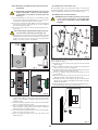
5.3.2 installing the rubber Profiles anD the receiver-
transmitter
Fit the batteries (supplied standard) in the top and
bottom transmitters, observing correct polarity
as indicated on the plastic container (TX1 and
TX2 Fig. 7).
• Fit the transmitters on the ends of the rubber profiles,
observing the direction indicated in Fig. 7, with the lens
on the front detection border of the edge.
• Fit the bottom rubber profile, sliding it downward along
the support profile, and taking it in contact against
the lower support spacer.
• Remove the front panel of the receiver-transmitter (ref.
a Fig. 7B).
Place the batteries (supplied standard) in the recei-
ver-transmitter, respecting polarity (Fig. 7A).
• Reinstall the front panel (ref. a Fig. 7B), fastening all the
supplied screws, and, when you install the front panel,
make sure that the lens on the front panel flashes
briefly to confirm correct installation.
TX1
TX2
L1
L2
• Fit the receiver-transmitter so that the logo is not
overturned, sliding it downward along the support
profile, until the rigid coupling is fully inserted in the
rubber profile.
• Check if the rubber profile and the receiver-transmitter
are in contact with each other.
• Fit the top rubber profile, sliding it downward along the
support profile, making sure that the rigid coupling is
fully inserted in the rubber profile.
• Check if the rubber profile and the receiver-transmitter
are in contact with each other.
• Secure the support spacer in the top hole which had
been left free.
5.3.3 installing the closing caPs
Fit the closing caps, checking if they are in contact with
the rubber profiles, and secure them with the self-tapping
screws (supplied standard) in the pre-drilled holes.
5.3.4 installing the fixeD receiver
ATTENTION before installing the fixed receiver, take
a note of the serial number, on the data-plate
on the rear, as indicated in Chap.8 FINAL OPE-
RATIONS.
1
2
2
3
3
4
7
6
6
5
Position the fixed receiver so that the lens on the front
panel (Fig. 8 ref. a) is at a height from 50 to 55 cm off the
ground. (HT see Fig. 5).
• Separate the bottom (Fig. 8 ref. d) from the front panel
(Fig.8 ref. e).
• Mark, for drilling the holes, the two screw securing points
(Fig. 8 ref f) - screws not supplied.
• Using adequate screws and expansion plugs, secure the
bottom of the receiver (Fig. 8 ref. d).
• To route the cables, use the facility in the lower part of
the receiver.
• Make the electrical connections as shown in Chap. 6,
using the rubber cable gripper (Fig.8 ref g).
• Assemble the front cover (Fig. 8 ref. e) to the bottom
(Fig. 8 ref. d), using the supplied screws (Fig. 8 ref. c),
supplied standard.
• Finish installing the receiver, by fitting the rubber protec-
tive devices (Fig. 8 ref. b) on the screws.
135
mm
45 mm
Fig. 7
Fig. 7A
Fig. 7B
Fig. 8
Fig. 9

16
ENGLISH
5.3.5 installing the couPling Profile
The coupling profile and its aluminium profile must be
cut to at least the same length as the finished edge
(dimension X in Fig. 5).
• We advise you to cut the coupling profile cleanly and
precisely.
• If you use this profile to install the fixed receiver, you must
cut the front rubber element to create a niche for
housing the receiver at a height from 50 to 55 cm off
the ground, using the perforation template supplied
standard. (see Fig. 9).
• Drill a series of 4 mm diam. intermediate holes on the
aluminium profile, in steps of about 40 cm.
• Rest the aluminium profile on the pillar and, to secure it,
use the holes you drilled.
Move the gate manually and check if - in closed
position - the safety edge is positioned on the
aluminium profile.
• Insert the rubber coupling profile downward in the
aluminium profile, until the niche reaches the height
suitable for positioning the fixed receiver.
• While moving the gate manually, check if - in closing
position - the edge penetrates inside the rubber
coupling profile.
• Place the electrical cables inside the coupling profile,
and make them exit from the lower part (Fig. 9).
• Secure the fixed receiver (par. 4.3.4).
• Finish the installation by fitting the closing caps on the
ends of the coupling profile.
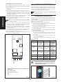
1 2 3 4 5
-
FSW
TX
N.C.
N.C.
-
+
6 ELECTRICAL CONNECTIONS
Make the electrical connections on the terminal-board of
the fixed receiver, consulting the instructions of the control
units, in the different configurations. To connect the fixed
receiver, use cables with a minimum section of 0.5 mm
2
,
and do not exceed a distance of 200 mt.
If you DO NOT use a unit with a Fal Safe input
you must connect terminal a to terminal d of
the fixed receiver.
7 OPERATING DIAGNOSTICS
The 6 LEDs on the fixed receiver make it possible to dia-
gnose installation and correct operation of all the devices
of safety edge.
Correct operation and installation is signalled by all 6 LEDs
lighting up on steady beam.
For the meaning of each LED, refer to Tab.5.
• If the safety edge is triggered, it always causes LEDS 4
and 6 to go OFF simultaneously.
• If the ray of the receiver-transmitter (Fig. 1 ref. e) is
interrupted, all 6 LEDs go OFF.
• If the top sensitive part of the edge is crushed, LEDs 1,
4 and 6 will go OFF.
• If the lower sensitive part of the edge is crushed, LEDs 3,
4 and 6 will go OFF.
• If LED 5 goes OFF, this means:
- The distance between the fixed receiver (Fig.1 ref.
i) and the receiver-transmitter (Fig.1 ref. e) is
too long.
- The fixed receiver and the receiver-transmitter are
not correctly aligned.
- The intensity of the signal is not sufficient for correct
operation.
Tab. 5
LED POSITION ON OFF FLASHING
LED 1
Top transmitter
ALIGNED
Top transmitter
NOT ALIGNED
Transmitter
aligned but
with BATTERIES
ALMOST
DISCHARGED
LED 2
Central tran-
smitter ALIGNED
Central
transmitter NOT
ALIGNED
Transmitter
aligned but
with BATTERIES
ALMOST
DISCHARGED
LED 3
Bottom tran-
smitter ALIGNED
Bottom
transmitter NOT
ALIGNED
Transmitter
aligned but
with BATTERIES
ALMOST
DISCHARGED
LED 4 Relay 1 ACTIVE
Relay 1 NOT
ACTIVE
---
LED 5
Infrared signal
sufficient
Infrared signal
insufficient
---
LED 6 Relay 2 ACTIVE
Relay 2 NOT
ACTIVE
---
After you have disaligned a device, the relevant
LED may flash for 2 or 3 seconds at realignment.
This brief flashing should not be considered as a
discharged battery signal.
Fig. 10
a
Fail-Safe (Connect to the fail safe terminal of the
control unit)
b
N.C. relay contact
c
Relay common contact
d
0 V
e
24 V
Fig. 11

17
ENGLISH
8 FINAL OPERATIONS
ATTENTION
A data-plate similar to the one in Fig. 12 is fitted on the
rear of the fixed receiver. The plate carries a serial number
identifying the safety edge system.
Copy the serial number of the fixed receiver in the space
indicated in Fig. 12 as Serial No. _______________, both in
chapter 11 of this Installation Manual and on the data-
plate of the User’s Guide.
If you replace the fixed receiver, copy the new serial
number, both on the data-plate of the Installation Manual
and in the User’s Guide.
If this procedure is not observed, this will render
the system’s conformity certificate invalid.
Correctly instruct the persons using the gate
about the operation of saety optical edge.
Hand the User’s Guide to the end-user.
9 REPLACING THE BATTERIES
Use lithium batteries model AA - L91 - 1.5V.
The replaced batteries must be disposed of in con-
formity with current legal regulations.
9.1 TOP AND BOTTOM TRANSMITTER
Procedure for replacing the batteries in the top transmitter
(Fig. 1 ref. c) and bottom transmitter (Fig. 1 ref. g):
1) Unscrew the screws of the caps (Fig. 1 ref. b - h) of
the transmitter whose batteries need changing and
remove the caps.
2) Extract the transmitter.
3) Unscrew the two screws which fasten the transmitter
and remove the cover.
4) Replace the batteries, respecting the polarities indica-
ted on the plastic container (Fig. 7).
5) To assemble, follow the instructions in chapter 5.3.2,
referring to the instructions for the top and bottom
transmitter.
9.2 RECEIVER-TRANSMITTER
To replace the batteries in the receiver-transmitter (Fig. 1
ref. e) follow the instructions in Chap. 5.3.2 referring to the
instructions for the receiver-transmitter.
10 MANUTENZIONE
Every 6 months: check the operation of the safety edge,
especially as regards the condition of the sensitive edge
and the LEDs of the fixed receiver.
If you see any LEDs flashing, consult TABLE 5. To replace
batteries, follow the instructions in Chap. 9.
11 IDENTIFICATION OF THE SYSTEM
Fig. 12

18
ENGLISH
12 INSTALLATION OF FIXED RECEIVER ON VEGA COLUMN
To install the column, consult instructions for the accessory. To install the fixed receiver, proceed as shown in Fig. 13:
1. Shorten the front housing (ref. a) of the column (ref. b) by 29 mm.
2. Make the electrical connections and re-install the front housing of the column.
3. Do not use the securing template (ref. c).
4. Assemble the support (ref. d) of the fixed receiver on the column cover, using the first hole (see detail A).
5. Separate the front panel (ref. e) of the fixed receiver from the bottom (ref. f).
6. Install the column cover.
7. Using the support (ref. d) and two screws, secure the bottom of the receiver (ref. f) on the aluminium profile of
the column.
8. Make the electrical connections and reinstall the front panel (ref. e) of the receiver.
9. Fit the spacers (ref. g).
Fig. 13

3
Data-plate
User’s guide
Read the instructions carefully before using the product and store them for future use.
Every person using the gate must be informed about the operation of the protective device.
GENERAL SAFETY REGULATIONS
Incorrect use of the product can cause serious damage to persons or things.
Some simple rules on behaviour can prevent accidental trouble:
Do not, on any account, stand in the system’s area of movement.
Do not allow persons, animals or things near the automated system, especially while it is operating.
Transit must occur while the door is fully open and with the automated system stopped. Keep the door under control
during the entire movement and prevent other people accessing the area involved.
Keep radio-controls, or other pulse generators that could activate the door, well away from children.
Do not allow children to play with the automated system, and especially with the MSE110W safety device.
Do not willingly obstruct door movement.
Prevent any branches or shrubs from interfering with door movement.
In the event of malfunctions, release the door to allow access and wait for qualified technical personnel to do the
necessary work.
Do not in any way modify the components of the MSE110W safety system.
Do not attempt any kind of repair or direct action whatever and contact the installer of the system only.
At least once every 6 months, arrange for the system installer to check the efficiency of the MSE 110 W safety
edge.
DESCRIPTION
Safety edge MSE 110 W is a safety device conforming to European Standard EN 12978 category 2, and can be installed
ONLY to protect the primary edge (for opening and closing) of the mobile leaf of a sliding gate.
Furthermore, it simultaneously performs the functions of a photocell (EN 12453 C + D).
OPERATION
The MSE110W safety edge enables the sliding leaf to stop whenever the sensitive edge is crushed or whenever the
beam of the two optical units is interrupted. If the edge is tripped, normal gate operation will be restored automatically
when the safety devices disengage.
MAINTENANCE
Every 6 months: arrange for the system installation technician to maintain the entire system, checking if any part of
the safety device is worn or damaged.
If too much dirt has settled on the optical units of the receiver-transmitter and/or the fixed receiver, gently clean the
lenses with a soft cloth.
Every month: check the signalling system on the fixed receiver, verifying that all the diagnostics LEDs are correctly
lighted.
If you see any unlighted and/or flashing LEDs, immediately contact the system installer.
MALFUNCTIONS
In the event of a malfunction, the safety device prevents use of the automated system.
Warn the system installer immediately.
IDENTIFICATION OF THE SYSTEM
If the installer does not compile the data-plate, the system’s certificate of conformity is rendered void.
•
•
•
•
•
•
•
•
•
•
•
ENGLISH

4
MAINTENANCE REGISTER
System data
Installer
Customer
Type of system
Serial No.
Installation date
Start-up
System configuration
PART MODEL SERIAL NUMBER
Operator
Safety device 1
Safety device 2
Pair of photocells 1
Pair of photocells 2
Control device 1
Control device 2
Radio control
Flashing lamp
Indication of residual risks and of foreseeable improper use
No. Date Job description Signatures
1
Technician
Customer
2
Technician
Customer
3
Technician
Customer
4
Technician
Customer
5
Technician
Customer
6
Technician
Customer
7
Technician
Customer
8
Technician
Customer
9
Technician
Customer
10
Technician
Customer
ENGLISH

ESPAÑOL
ADVERTENCIAS PARA EL INSTALADOR
REGLAS GENERALES PARA LA SEGURIDAD
ATENCION! Es sumamente importante para la seguridad de las personas seguir atentamente las presentes instrucciones. Una instalación incorrecta o
un uso impropio del producto puede causar graves daños a las personas.
Lean detenidamente las instrucciones antes de instalar el producto.
Los materiales del embalaje (plástico, poliestireno, etc.) no deben dejarse al alcance de los niños, ya que constituyen fuentes potenciales de peligro.
Guarden las instrucciones para futuras consultas.
Este producto ha sido proyectado y fabricado exclusivamente para la utilización indicada en el presente manual. Cualquier uso diverso del previsto podría perjudicar el fun-
cionamiento del producto y/o representar fuente de peligro.
No instalen el aparato en atmósfera explosiva: la presencia de gas o humos inflamables constituye un grave peligro para la seguridad.
GENIUS declina toda responsabilidad relativa a la seguridad y al buen funcionamiento de la automación si se utilizan componentes de la instalación que no sean de produc-
ción GENIUS.
Para el mantenimiento utilicen exclusivamente piezas originales GENIUS
El usuario debe abstenerse de intentar reparar o de intervenir directamente, y debe dirigirse exclusivamente a personal cualificado GENIUS o a centros de asistencia GENIUS.
El borde de seguridad NO debe utilizarse como dispositivo de parada, normal o de emergencia, de puertas o cancelas motorizadas.
El borde de seguridad si se utiliza en estas aplicaciones NO garantiza la seguridad:
compuertas y mamparos.
puertas de ascensores.
puertas de vehículos.
puertas blindadas.
puertas utilizadas principalmente para retener animales.
telones de teatro en tela.
barreras ferroviarias.
barreras utilizadas exclusivamente para vehículos.
El borde de seguridad NO debe utilizarse como parada de emergencia de máquinas operadoras.
El borde de seguridad NO garantiza una correcta funcionalidad si se instala en ambientes con un nivel de contaminación electromagnética superior al especificado en la
norma EN 61000-6-4 o EN 55014-2, cuando se monta en puertas de garaje de uso doméstico.
Todo lo que no esté previsto expresamente en las presentes instrucciones debe entenderse como no permitido
DEUTSCH
HINWEISE FÜR DEN INSTALLATIONSTECHNIKER
ALLGEMEINE SICHERHEITSVORSCHRIFTEN
ACHTUNG! Um die Sicherheit von Personen zu gewährleisten, sollte die Anleitung aufmerksam befolgt werden. Eine falsche Installation oder ein
fehlerhafter Betrieb des Produktes können zu schwerwiegenden Personenschäden führen.
Bevor mit der Installation des Produktes begonnen wird, sollten die Anleitungen aufmerksam gelesen werden.
Das Verpackungsmaterial (Kunststoff, Styropor, usw.) sollte nicht in Reichweite von Kindern aufbewahrt werden, da es eine potentielle Gefahrenquelle darstellt.
Die Anleitung sollte aufbewahrt werden, um auch in Zukunft Bezug auf sie nehmen zu können.
Dieses Produkt wurde ausschließlich für den in diesen Unterlagen angegebenen Gebrauch entwickelt und hergestellt. Jeder andere Gebrauch, der nicht ausdrücklich angegeben
ist, könnte die Unversehrtheit des Produktes beeinträchtigen und/oder eine Gefahrenquelle darstellen.
Das Gerät sollte nicht in explosionsgefährdeten Umgebungen installiert werden: das Vorhandensein von entflammbaren Gasen oder Rauch stellt ein schwerwiegendes Siche-
rheitsrisiko dar.
Die Firma GENIUS lehnt jede Haftung hinsichtlich der Sicherheit und des störungsfreien Betriebs der Automatik ab, soweit Komponenten auf der Anlage eingesetzt werden, die
nicht im Hause GENIUS hergestellt urden.
Bei der Instandhaltung sollten ausschließlich Originalteile der Firma GENIUS verwendet werden.
Der Benutzer darf direkt keine Versuche für Reparaturen oder Arbeiten vornehmen und hat sich ausschließlich an qualifiziertes Fachpersonal GENIUS oder an Kundendienstzentren
GENIUS zu wenden.
Die Sicherheitsleiste darf NICHT als Vorrichtung für das normale Anhalten oder die Notabschaltung von mit Motor angetriebenen Türen oder Toren verwendet werden.
Wenn die Sicherheitsleiste bei den folgenden Anwendungen eingesetzt wird, gewährleistet sie deren Sicherheit NICHT:
Schleusen und Dämme.
Aufzugstüren.
Fahrzeugtüren.
Panzertüren.
vorwiegend für das Einschließen von Tieren verwendete Türen.
Theatervorhänge aus Stoff.
Bahnschranken.
Ausschließlich für Fahrzeuge verwendete Schranken.
Die Sicherheitsleiste darf NICHT als Notabschaltung von Antriebsmaschinen verwendet werden.
Die Sicherheitsleiste gewährleistet den einwandfreien Betrieb NICHT, wenn sie in Umgebungen mit elektromagnetischen Belastungen über den in der Norm EN 61000-6-4 oder EN
55014-2 (bei Montage an Garagentoren für Wohngebäude) angegebenen Werten installiert ist.
Alle Vorgehensweisen, die nicht ausdrücklich in der vorliegenden Anleitung vorgesehen sind, sind nicht zulässig
NEDERLANDS
WAARSCHUWINGEN VOOR DE INSTALLATEUR
ALGEMENE VEILIGHEIDSVOORSCHRIFTEN
LET OP! Het is belangrijk voor de veiligheid dat deze hele instructie zorgvuldig wordt opgevolgd. Een onjuiste installatie of foutief gebruik van het
product kunnen ernstig persoonlijk letsel veroorzaken.
Lees de instructies aandachtig door alvorens te beginnen met de installatie van het product.
De verpakkingsmaterialen (plastic, polystyreen, enz.) mogen niet binnen het bereik van kinderen worden gelaten, want zij vormen een mogelijke bron van gevaar.
Bewaar de instructies voor raadpleging in de toekomst.
Dit product is uitsluitend ontworpen en gebouwd voor het doel dat in deze documentatie wordt aangegeven. Elk ander gebruik, dat niet uitdrukkelijk wordt vermeld, zou het
product kunnen beschadigen en/of een bron van gevaar kunnen vormen.
Installeer het apparaat niet in een explosiegevaarlijke omgeving: de aanwezigheid van ontvlambare gassen of dampen vormt een ernstig gevaar voor de veiligheid.
GENIUS aanvaardt geen enkele aansprakelijkheid voor wat betreft de veiligheid en de goede werking van het automatische systeem, als er in de installatie gebruik gemaakt
wordt van componenten die niet door GENIUS zijn geproduceerd.
Gebruik voor het onderhoud uitsluitend originele GENIUS-onderdelen.
De gebruiker mag zelf geen pogingen ondernemen tot reparaties of andere directe ingrepen, en dient zich uitsluitend te wenden tot gekwalificeerd en geautoriseerd GENIUS-
personeel of een erkend GENIUS-servicecentrum.
De veiligheidslijst mag NIET worden gebruikt als voorziening voor het normaal stoppen of de noodstop van gemotoriseerde deuren of poorten.
Als de veiligheidslijst wordt gebruikt bij deze toepassingen, wordt de veiligheid daarvan NIET gegarandeerd:
schuttingen en schotten.
liftdeuren.
deuren van voertuigen.
gepantserde deuren.
deuren die hoofdzakelijk worden gebruikt om dieren op te sluiten.
stoffen toneelgordijnen.
spoorwegslagbomen.
slagbomen die uitsluitend voor voertuigen worden gebruikt.
De veiligheidslijst MSE110W mag NIET worden gebruikt als noodstopvoorziening voor werkmachine.
De correcte werking van de veiligheidslijst MSE110W wordt NIET gegarandeerd als hij is geïnstalleerd in omgevingen waar het niveau van elektromagnetische vervuiling hoger is
dan dat aangegeven in de norm EN 61000-6-4 of EN 55014-2 als hij op garagedeuren bij woningen wordt gemonteerd.
Alles wat niet uitdrukkelijk in deze instructies wordt aangegeven, is niet toegestaan
1.
2.
3.
4.
5.
6.
7.
8.
9.
10.
•
•
•
•
•
•
•
•
11.
12.
13.
1.
2.
3.
4.
5.
6.
7.
8.
9.
10.
•
•
•
•
•
•
•
•
11.
12.
13.
1.
2.
3.
4.
5.
6.
7.
8.
9.
10.
•
•
•
•
•
•
•
•
11.
12.
13.

Le descrizioni e le illustrazioni del presente manuale non sono impegnative. La GENIUS si riserva il diritto, lasciando inalterate le carat-
teristiche essenziali dell’apparecchiatura, di apportare in qualunque momento e senza impegnarsi ad aggiornare la presente pub-
blicazione, le modifiche che essa ritiene convenienti per miglioramenti tecnici o per qualsiasi altra esigenza di carattere costruttivo
o commerciale.
The descriptions and illustrations contained in the present manual are not binding. GENIUS reserves the right, whilst leaving the main
features of the equipments unaltered, to undertake any modifications it holds necessary for either technical or commercial reasons,
at any time and without revising the present publication.
Les descriptions et les illustrations du présent manuel sont fournies à titre indicatif. GENIUS se réserve le droit d’apporter à tout moment
les modifications qu’elle jugera utiles sur ce produit tout en conservant les caractéristiques essentielles, sans devoir pour autant mettre
à jour cette publication.
Die Beschreibungen und Abbildungen in vorliegendem Handbuch sind unverbindlich. GENIUS behält sich das Recht vor, ohne die
wesentlichen Eigenschaften dieses Gerätes zu verändern und ohne Verbindlichkeiten in Bezug auf die Neufassung der vorliegenden
Anleitungen, technisch bzw. konstruktiv/kommerziell bedingte Verbesserungen vorzunehmen.
Las descripciones y las ilustraciones de este manual no comportan compromiso alguno. GENIUS se reserva el derecho, dejando
inmutadas las características esenciales de los aparatos, de aportar, en cualquier momento y sin comprometerse a poner al día la
presente publicación, todas las modificaciones que considere oportunas para el perfeccionamiento técnico o para cualquier otro
tipo de exigencia de carácter constructivo o comercial.
De beschrijvingen in deze handleiding zijn niet bindend. GENIUS behoudt zich het recht voor op elk willekeurig moment de verande-
ringen aan te brengen die het bedrijf nuttig acht met het oog op technische verbeteringen of alle mogelijke andere productie- of
commerciële eisen, waarbij de fundamentele eigenschappen van de apparaat gehandhaafd blijven, zonder zich daardoor te
verplichten deze publicatie bij te werken.
Timbro del Rivenditore:/ Distributor’s Stamp:/ Timbre de l’Agent:/ Fachhändlerstempel:/
Sello del Revendedor:/ Stempel van de dealer:
GENIUS S.p.A.
Via Padre Elzi, 32
24050 Grassobbio (BG) - ITALIA
Tel.: 035/4242511
Fax: 035/4242600
www.geniusg.Com
00058I0588 Rev.1
-
 1
1
-
 2
2
-
 3
3
-
 4
4
-
 5
5
-
 6
6
-
 7
7
-
 8
8
-
 9
9
-
 10
10
-
 11
11
-
 12
12
-
 13
13
-
 14
14


in altre lingue
- English: Genius Edge Operating instructions
- français: Genius Edge Mode d'emploi
- Deutsch: Genius Edge Bedienungsanleitung
- Nederlands: Genius Edge Handleiding