
THALIA
D812808 00100_04 04-10-16
ISTRUZIONI DI INSTALLAZIONE
INSTALLATION MANUAL
INSTRUCTIONS D’INSTALLATION
MONTAGEANLEITUNG
INSTRUCCIONES DE INSTALACION
INSTALLATIEVOORSCHRIFTEN
THALIA
Attenzione! Leggere attentamente le “Avvertenze” all’interno! Caution! Read “Warnings” inside carefully! Attention! Veuillez lire attentivement les Avertissements qui se trouvent à l’intérieur! Achtung! Bitte lesen Sie
aufmerksam die „Hinweise“ im Inneren! ¡Atención¡ Leer atentamente las “Advertencias”en el interior! Let op! Lees de “Waarschuwingen”tigre aan de binnenkant zorgvuldig!
QUADRO COMANDO
CONTROL PANEL
CENTRALE DE COMMANDE
SELBSTÜBERWACHENDE STEUERUNG
CUADRO DE MANDOS
BEDIENINGSPANEEL

INSTALLER WARNINGS
Anything that is not explicitly provided for in the installation ma-
nual is not allowed. The operator’s proper operation can only be
guaranteed if the information given is complied with. The Firm shall
not be answerable for damage caused by failure to comply with the
instructions featured herein.
While we will not alter the product’s essential features, the Firm reserves
the right, at any time, to make those changes deemed opportune to
improve the product from a technical, design or commercial point of
view, and will not be required to update this publication accordingly.
WARNING! Important safety instructions. Carefully read and comply with
all the warnings and instructions that come with the product as incorrect
installation can cause injury to people and animals and damage to property.
The warnings and instructions give important information regarding safety,
installation, use and maintenance. Keep hold of instructions so that you can
attach them to the technical le and keep them handy for future reference.
GENERAL SAFETY
This product has been designed and built solely for the purpose indicated herein.
Uses other than those indicated herein might cause damage to the product and
create a hazard.
- The units making up the machine and its installation must meet the requirements
of the following European Directives, where applicable: 2014/30/EC, 2014/35/
EC, 2006/42/EC, 2011/305/EC, 99/05/EC and later amendments. For all countries
outside the EEC, it is advisable to comply with the standards mentioned, in ad-
dition to any national standards in force, to achieve a good level of safety.
- The Manufacturer of this product (hereinafter referred to as the “Firm”) disclaims
all responsibility resulting from improper use or any use other than that for
which the product has been designed, as indicated herein, as well as for failure
to apply Good Practice in the construction of entry systems (doors, gates, etc.)
and for deformation that could occur during use.
- Installation must be carried out by qualied personnel (professional installer,
according to EN 12635), in compliance with Good Practice and current code.
- Before installing the product, make all structural changes required to produce
safety gaps and to provide protection from or isolate all crushing, shearing and
dragging hazard areas and danger zones in general in accordance with the
provisions of standards EN 12604 and 12453 or any local installation standards.
Check that the existing structure meets the necessary strength and stability
requirements.
- Before commencing installation, check the product for damage.
- The Firm is not responsible for failure to apply Good Practice in the construction
and maintenance of the doors, gates, etc. to be motorized, or for deformation
that might occur during use.
- Make sure the stated temperature range is compatible with the site in which the
automated system is due to be installed.
- Do not install this product in an explosive atmosphere: the presence of ammable
fumes or gas constitutes a serious safety hazard.
- Disconnect the electricity supply before performing any work on the system.
Also disconnect buer batteries, if any are connected.
- Before connecting the power supply, make sure the product’s ratings match the
mains ratings and that a suitable residual current circuit breaker and overcurrent
protection device have been installed upline from the electrical system. Have
the automated system’s mains power supply tted with a switch or omnipolar
thermal-magnetic circuit breaker with a contact separation that provide full
disconnection under overvoltage category III conditions.
- Make sure that upline from the mains power supply there is a residual current
circuit breaker that trips at no more than 0.03A as well as any other equipment
required by code.
- Make sure the earth system has been installed correctly: earth all the metal parts
belonging to the entry system (doors, gates, etc.) and all parts of the system
featuring an earth terminal.
- Installation must be carried out using safety devices and controls that meet
standards EN 12978 and EN 12453.
- Impact forces can be reduced by using deformable edges.
- In the event impact forces exceed the values laid down by the relevant standards,
apply electro-sensitive or pressure-sensitive devices.
- Apply all safety devices (photocells, safety edges, etc.) required to keep the
area free of impact, crushing, dragging and shearing hazards. Bear in mind the
standards and directives in force, Good Practice criteria, intended use, the instal-
lation environment, the operating logic of the system and forces generated by
the automated system.
- Apply all signs required by current code to identify hazardous areas (residual
risks). All installations must be visibly identied in compliance with the provisions
of standard EN 13241-1.
- Once installation is complete, apply a nameplate featuring the door/gate’s data.
- This product cannot be installed on leaves incorporating doors (unless the motor
can be activated only when the door is closed).
- If the automated system is installed at a height of less than 2.5 m or is accessible,
the electrical and mechanical parts must be suitably protected.
- For roller shutter automation only
1) The motor’s moving parts must be installed at a height greater than 2.5 m
above the oor or other surface from which they may be reached.
2) The gearmotor must be installed in a segregated and suitably protected space
so that it cannot be reached without the aid of tools.
- Install any xed controls in a position where they will not cause a hazard, away
from moving parts. More specically, hold-to-run controls must be positioned
within direct sight of the part being controlled and, unless they are key operated,
must be installed at a height of at least 1.5 m and in a place where they cannot
be reached by the public.
- Apply at least one warning light (ashing light) in a visible position, and also
attach a Warning sign to the structure.
- Attach a label near the operating device, in a permanent fashion, with informa-
tion on how to operate the automated system’s manual release.
- Make sure that, during operation, mechanical risks are avoided or relevant
protective measures taken and, more specically, that nothing can be banged,
crushed, caught or cut between the part being operated and surrounding parts.
- Once installation is complete, make sure the motor automation settings are
correct and that the safety and release systems are working properly.
- Only use original spare parts for any maintenance or repair work. The Firm dis-
claims all responsibility for the correct operation and safety of the automated
system if parts from other manufacturers are used.
- Do not make any modications to the automated system’s components unless
explicitly authorized by the Firm.
- Instruct the system’s user on what residual risks may be encountered, on the
control systems that have been applied and on how to open the system manu-
ally in an emergency. give the user guide to the end user.
- Dispose of packaging materials (plastic, cardboard, polystyrene, etc.) in accord-
ance with the provisions of the laws in force. Keep nylon bags and polystyrene
out of reach of children.
WIRING
WARNING! For connection to the mains power supply, use: a multicore cable with
a cross-sectional area of at least 5x1.5mm
2
or 4x1.5mm
2
when dealing with three-
phase power supplies or 3x1.5mm
2
for single-phase supplies (by way of example,
type H05RN-F cable can be used with a cross-sectional area of 4x1.5mm
2
). To con-
nect auxiliary equipment, use wires with a cross-sectional area of at least 0.5 mm
2
.
- Only use pushbuttons with a capacity of 10A-250V or more.
- Wires must be secured with additional fastening near the terminals (for example,
using cable clamps) in order to keep live parts well separated from safety extra
low voltage parts.
- During installation, the power cable must be stripped to allow the earth wire
to be connected to the relevant terminal, while leaving the live wires as short
as possible. The earth wire must be the last to be pulled taut in the event the
cable’s fastening device comes loose.
WARNING! safety extra low voltage wires must be kept physically separate from
low voltage wires.
Only qualied personnel (professional installer) should be allowed to access
live parts.
CHECKING THE AUTOMATED SYSTEM AND MAINTENANCE
Before the automated system is nally put into operation, and during maintenance
work, perform the following checks meticulously:
- Make sure all components are fastened securely.
- Check starting and stopping operations in the case of manual control.
- Check the logic for normal or personalized operation.
- For sliding gates only: check that the rack and pinion mesh correctly with 2 mm
of play along the full length of the rack; keep the track the gate slides on clean
and free of debris at all times.
- For sliding gates and doors only: make sure the gate’s running track is straight
and horizontal and that the wheels are strong enough to take the weight of the
gate.
- For cantilever sliding gates only: make sure there is no dipping or swinging
during operation.
- For swing gates only: make sure the leaves’ axis of rotation is perfectly vertical.
-For barriers only: before opening the door, the spring must be decompressed
(vertical boom).
- Check that all safety devices (photocells, safety edges, etc.) are working properly
and that the anti-crush safety device is set correctly, making sure that the force
of impact measured at the points provided for by standard EN 12445 is lower
than the value laid down by standard EN 12453.
- Impact forces can be reduced by using deformable edges.
- Make sure that the emergency operation works, where this feature is provided.
- Check opening and closing operations with the control devices applied.
- Check that electrical connections and cabling are intact, making extra sure that
insulating sheaths and cable glands are undamaged.
- While performing maintenance, clean the photocells’ optics.
- When the automated system is out of service for any length of time, activate the
emergency release (see “EMERGENCY OPERATION” section) so that the operated
part is made idle, thus allowing the gate to be opened and closed manually.
-
If the power cord is damaged, it must be replaced by the manufacturer or their
technical assistance department or other such qualied person to avoid any risk .
- If “D” type devices are installed (as dened by EN12453), connect in unveried
mode, foresee mandatory maintenance at least every six months
- The maintenance described above must be repeated at least once yearly or at
shorter intervals where site or installation conditions make this necessary.
WARNING!
Remember that the drive is designed to make the gate/door easier to use and
will not solve problems as a result of defective or poorly performed installation
or lack of maintenance
SCRAPPING
Materials must be disposed of in accordance with the regulations in
force. Do not throw away your discarded equipment or used batteries
with household waste. You are responsible for taking all your waste
electrical and electronic equipment to a suitable recycling centre.
DISMANTLING
If the automated system is being dismantled in order to be reassembled at another
site, you are required to:
- Cut o the power and disconnect the whole electrical system.
- Remove the actuator from the base it is mounted on.
- Remove all the installation’s components.
- See to the replacement of any components that cannot be removed or happen
to be damaged.
DECLARATIONS OF CONFORMITY CAN BE FOUND AT http://www.bft-
automation.com/CE
INSTRUCTIONS FOR USE AND ASSEMBLY CAN BE FOUND IN THE DOWN-
LOAD SECTION.
D811766_16
THALIA - 3
D812808 00100_04

AVVERTENZE PER L’UTILIZZATORE ( I )
ATTENZIONE! Importanti istruzioni di sicurezza.
Leggere e seguire attentamente le Avvertenze
e le Istruzioni che accompagnano il prodotto
poiché un uso improprio può causare danni a
persone, animali o cose. Conservare le istruzioni
per consultazioni future e trasmetterle ad even-
tuali subentranti nell’uso dell’impianto.
Questo prodotto dovrà essere destinato solo
all’uso per il quale è stato espressamente insta-
llato. Ogni altro uso è da considerarsi improprio
e quindi pericoloso. Il costruttore non può essere
considerato responsabile per eventuali danni
causati da usi impropri, erronei e irragionevoli.
SICUREZZA GENERALE
Nel ringraziarVi per la preferenza accordata a questo
prodotto, la Ditta è certa che da esso otterrete le
prestazioni necessarie al Vostro uso.
Questo prodotto risponde alle norme riconosciute
della tecnica e della disposizioni relative alla si-
curezza se correttamente installato da personale
qualicato ed esperto (installatore professionale).
L’automazione, se installata ed utilizzata corretta-
mente, soddisfa gli standard di sicurezza nell’uso.
Tuttavia è opportuno osservare alcune regole di
comportamento per evitare inconvenienti acci-
dentali:
- Tenere bambini, persone e cose fuori dal raggio
d’azione dell’automazione, in particolare durante
il movimento.
- Non permettere a bambini di giocare o sostare nel
raggio di azione dell’automazione.
- L’apparecchio può essere utilizzato da bambini di
età non inferiore a 8 anni e da persone con ridot-
te capacità siche, sensoriali o mentali, o prive di
esperienza o della necessaria conoscenza, purché
sotto sorveglianza oppure dopo che le stesse
abbiano ricevuto istruzioni relative all’uso sicuro
dell’apparecchio e alla comprensione dei pericoli
ad esso inerenti. I bambini non devono giocare con
l’apparecchio. La pulizia e la manutenzione desti-
nata ad essere eettuata dall’utilizzatore non deve
essere eettuata da bambini senza sorveglianza.
- I bambini devono essere sorvegliati per sincerarsi
che non giochino con l’apparecchio. Non permet-
tere ai bambini di giocare con i controlli ssi. Tenere
i telecomandi lontani dai bambini.
-
Evitare di operare in prossimità delle cerniere o organi
meccanici in movimento.
-
Non contrastare il movimento dell’anta e non ten-
tare di aprire manualmente la porta se non è stato
sbloccato l’attuatore con l’apposita manopola di
sblocco.
-
Non entrare nel raggio di azione della porta o can-
cello motorizzati durante il loro movimento.
- Non lasciare radiocomandi o altri dispositivi di
comando alla portata dei bambini onde evitare
azionamenti involontari.
- L’attivazione dello sblocco manuale potrebbe
causare movimenti incontrollati della porta se in
presenza di guasti meccanici o di condizioni di
squilibrio.
- In caso di apritapparelle: sorvegliare la tapparella
in movimento e tenere lontano le persone nché
non è completamente chiusa. Porre cura quando si
aziona lo sblocco se presente, poiché una tapparella
aperta potrebbe cadere rapidamente in presenza
di usura o rotture.
-
La rottura o l’usura di organi meccanici della porta
(parte guidata), quali ad esempio cavi, molle, sup-
porti, cardini, guide.. potrebbe generare pericoli. Far
controllare periodicamente l’impianto da personale
qualicato ed esperto (installatore professionale)
secondo quanto indicato dall’installatore o dal
costruttore della porta.
- Per ogni operazione di pulizia esterna, togliere
l’alimentazione di rete.
- Tenere pulite le ottiche delle fotocellule ed i dispo-
sitivi di segnalazione luminosa. Controllare che rami
ed arbusti non disturbino i dispositivi di sicurezza.
- Non utilizzare l’automatismo se necessita di
interventi di riparazione. In caso di guasto o di
malfunzionamento dell’automazione, togliere
l’alimentazione di rete sull’automazione, astenersi
da qualsiasi tentativo di riparazione o intervento
diretto e rivolgersi solo a personale qualicato ed
esperto (installatore professionale) per la neces-
saria riparazione o manutenzione. Per consentire
l’accesso, attivare lo sblocco di emergenza (se
presente).
-
Per qualsiasi intervento diretto sull’automazione o
sull’impianto non previsto dal presente manuale,
avvalersi di personale qualicato ed esperto (insta-
llatore professionale).
- Con frequenza almeno annuale far verifi-
care l’integrità e il corretto funzionamento
dell’automazione da personale qualificato ed
esperto (installatore professionale), in particolare
di tutti i dispositivi di sicurezza.
- Gli interventi d’installazione, manutenzione e
riparazione devono essere documentati e la
relativa documentazione tenuta a disposizione
dell’utilizzatore.
- Il mancato rispetto di quanto sopra può creare
situazioni di pericolo.
DEMOLIZIONE
L’eliminazione dei materiali va fatta rispettan-
do le norme vigenti. Non gettate il vostro
apparecchio scartato, le pile o le batterie usate
nei riuti domestici. Avete la responsabilità di
restituire tutti i vostri riuti da apparecchia-
ture elettriche o elettroniche lasciandoli in
un punto di raccolta dedicato al loro riciclo.
Tutto quello che non è espressamente previs-
to nel manuale d’uso, non è permesso. ll buon
funzionamento dell’operatore è garantito solo
se vengono rispettate le prescrizioni riportate
in questo manuale. La Ditta non risponde dei
danni causati dall’inosservanza delle indicazioni
riportate in questo manuale.
Lasciando inalterate le caratteristiche essenziali
del prodotto, la Ditta si riserva di apportare in
qualunque momento le modiche che essa ritie-
ne convenienti per migliorare tecnicamente, cos-
truttivamente e commercialmente il prodotto,
senza impegnarsi ad aggiornare la presente
pubblicazione.
USER WARNINGS (GB)
WARNING! Important safety instructions. Ca-
refully read and comply with the Warnings and
Instructions that come with the product as impro-
per use can cause injury to people and animals
and damage to property. Keep the instructions
for future reference and hand them on to any
new users.
This product is meant to be used only for the
D811767_07
8 - THALIA
D812808 00100_04

purpose for which it was explicitly installed.
Any other use constitutes improper use and,
consequently, is hazardous. The manufacturer
cannot be held liable for any damage as a result
of improper, incorrect or unreasonable use.
GENERAL SAFETY
Thank you for choosing this product. The Firm is
condent that its performance will meet your ope-
rating needs.
This product meets recognized technical standards
and complies with safety provisions when installed
correctly by qualied, expert personnel (professional
installer).
If installed and used correctly, the automated system
will meet operating safety standards. Nonetheless,
it is advisable to observe certain rules of behaviour
so that accidental problems can be avoided:
- Keep adults, children and property out of range of
the automated system, especially while it is moving.
- Do not allow children to play or stand within range
of the automated system.
- The unit can be used by children over 8 years old
and by people with reduced physical, sensory or
mental capabilities or with no experience or neces-
sary knowledge on condition they are supervised
or trained about the safe use of the equipment
and understand the risks involved. Children must
not play with the unit. Cleaning and maintenance
must not be performed by unsupervised children.
- Children must be supervised to ensure they do not
play with the device. Do not allow children to play
with the xed controls. Keep remote controls out
of reach of children.
-
Do not work near hinges or moving mechanical parts.
- Do not hinder the leaf’s movement and do not
attempt to open the door manually unless the ac-
tuator has been released with the relevant release
knob.
- Keep out of range of the motorized door or gate
while they are moving.
- Keep remote controls or other control devices out
of reach of children in order to avoid the automated
system being operated inadvertently.
- The manual release’s activation could result in un-
controlled door movements if there are mechanical
faults or loss of balance.
- When using roller shutter openers: keep an eye
on the roller shutter while it is moving and keep
people away until it has closed completely. Exercise
care when activating the release, if such a device
is tted, as an open shutter could drop quickly in
the event of wear or breakage.
- The breakage or wear of any mechanical parts of
the door (operated part), such as cables, springs,
supports, hinges, guides…, may generate a hazard.
Have the system checked by qualied, expert per-
sonnel (professional installer) at regular intervals
according to the instructions issued by the installer
or manufacturer of the door.
- When cleaning the outside, always cut o mains
power.
- Keep the photocells’ optics and illuminating in-
dicator devices clean. Check that no branches or
shrubs interfere with the safety devices.
- Do not use the automated system if it is in need of
repair. In the event the automated system breaks
down or malfunctions, cut o mains power to the
system; do not attempt to repair or perform any
other work to rectify the fault yourself and instead
call in qualied, expert personnel (professional
installer) to perform the necessary repairs or main-
tenance. To allow access, activate the emergency
release (where tted).
- If any part of the automated system requires direct
work of any kind that is not contemplated herein,
employ the services of qualied, expert personnel
(professional installer).
- At least once a year, have the automated system, and
especially all safety devices, checked by qualied,
expert personnel (professional installer) to make
sure that it is undamaged and working properly.
- A record must be made of any installation, main-
tenance and repair work and the relevant docu-
mentation kept and made available to the user on
request.
- Failure to comply with the above may result in
hazardous situations.
SCRAPPING
Materials must be disposed of in accordance
with the regulations in force. Do not throw
away your discarded equipment or used bat-
teries with household waste. You are respon-
sible for taking all your waste electrical and
electronic equipment to a suitable recycling
centre.
Anything that is not explicitly provided for in the
user guide is not allowed. The operator’s proper
operation can only be guaranteed if the instruc-
tions given herein are complied with. The Firm
shall not be answerable for damage caused by
failure to comply with the instructions featured
herein.
While we will not alter the product’s essential
features, the Firm reserves the right, at any time,
to make those changes deemed opportune to
improve the product from a technical, design or
commercial point of view, and will not be required
to update this publication accordingly.
D811767_07
THALIA - 9
D812808 00100_04

A
C
JP5 JP7
Y #
F2 3,15 AT
F1 1.25 AT
(220-230V)
F1 2.5 AT (120V)
ANT.
ANT
SHIELD
24V
220-230V ~
*
S2
S1
S3
*
0,75
0,75
0,75
0,75
0,75
*
L N
10
11
L
N
M1
220-230V ~
*
14 15
20
21
26 27
40
41
42
43
44
45 50
51
52
60 61
62
70
71
72
73
74 75
+
M2
24V
AUX 3
(MAX 24V 1A)
- REF SWE
+ REF SWE
SWC 1 / SW 1 / ENC1A
SWO 1 / SW 2 / ENC1B
SWC2 / ENC2A
SWO2 / ENC2B
24V -
24V +
24 VSafe+
COM
IC 1
IC 2
COM
SAFE 1
STOP
FAULT 1
SAFE 2
FAULT 2
-
+
-
NO
NO
NC
NC
NC
JP21
3x2,5 mm
2
*
3x2,5 mm
2
230V
(*)
24V
(*) 110V
26
AUX 3 = 0
AUX 3 = 2
AUX 3 = 3
AUX 3 = 4
AUX 3 = 5
AUX 3 = 6
AUX 3 = 7
AUX 3 = 8
AUX 3 = 1
27
1
D
JP3
725150 70
24V ~
26 27 50 51
24 V~
SCA
2
1
TX1
2
1
RX1
4
5
3
SAFE 1 = 0
220
I
NSTALLAZIONE VELOCE-QUICK INSTALLATION-INSTALLATION RAPIDE
SCHNELLINSTALLATION-INSTALACIÓN RÁPIDA - SNELLE INSTALLATIE
PREDISPOSIZIONE TUBI
TUBE ARRANGEMENT
PRÉDISPOSITION DES TUYAUX
VORBEREITUNG DER LEITUNGEN
DISPOSICIÓN DE TUBOS
VOORBEREIDING LEIDINGEN
* Vedere specica motore
See motor specications
Consultez les caractéristiques du moteur
Siehe Motordaten
Véase especicaciones motor
Zie motorspecicatie
Collegamento di 1 coppia di fotocellule non vericate, per fotocellule vericate vedere pagine seguenti.
Connection of 1 couple of untested photocells, for tested photocells see the following pages.
Connexion d’une paire de photocellules non vériées, pour les photocellules vériées consultez les
pages suivantes.
Anschluss von einem Paar nicht überprüfter Fotozellen, für überprüfte Fotozelle siehe die
folgenden Seiten.
Conexión de 1 par de fotocélulas no comprobadas, para fotocélulas comproabdas véanse las
siguientes páginas.
Aansluiting van 1 paar niet-geverieerde fotocellen. Raadpleeg de volgende pagina’s voor
geverieerde fotocellen.
Connettore scheda opzionale,
SCS1 optional board connector,
Connecteur carte facultative,
Steckverbinder Zusatzkarte,
Conector de la tarjeta opcional,
Connector optionele kaart.
Connettore programmatore palmare,
Palmtop programmer connector,
Connecteur programmateur de poche,
Steckverbinder Palmtop-Programmierer,
Conector del programador de bolsillo,
Connector programmeerbare palmtop.
Display + tasti programmazione,
Display plus programming keys,
Acheur et touches de programmation,
Display und Programmierungstasten,
Pantalla más botones de programación,
Display meerdere toetsen
programmeur.
Altre tensioni disponibili a richiesta
Other voltages available on request
Autres tensions disponibles sur demande
Weitere Spannungen auf Anfrage erhältlich
Otras tensiones disponibles a petición
Andere spanningen op aanvraag beschikbaar
Alimentazione / Power supply
Alimentation /
Stromversorgung
Alimentación /Voeding
Motore / Motor / moteur
Motor /Eindaanslag/Encoder
AUX
Ingressi necorsa/encoder
Encoder/limit switch inputs
Entrées des ns de course /
encodeur
Eingänge Anschlag/Encoder
Entradas nales de carrera
Encoder/ingangen
Alimentazione accessori
Accessories power supply
Alimentation des accessoires
Stromversorgung Zubehör
Alimentación accesorios
Voeding accessoires
Comandi / Commands
Commandes/Bedienelemente
Mandos/ Commando’s
Sicurezze
Safety devices
Sécurités
Sicherheitsvorrichtungen
Dispositivos de seguridad
Veiligheden
Antenna
Antenne
Antena
Antenne
14 - THALIA
D812808 00100_04

ENGLISH FRANÇAIS ESPAÑOL
NEDERLANDS
DEUTSCHITALIANO
E’ NECESSARIO SEGUIRE QUESTA SEQUENZA DI REGOLAZIONI:
1 - Regolazione dei necorsa
2 - Autoset
3 - Programmazione radiocomando
4 - Eventuali regolazioni dei parametri / logiche
Dopo ogni modica della posizione dei necorsa e’ necessario eseguire un nuovo autoset.
Dopo ogni modica del tipo motore e’ necessario eseguire un nuovo autoset.
Se si utilizza il menu semplicato:
- Nel caso di motori LUX-BT, LUX G-BT - GIUNO ULTRA BT A 20 GIUNO ULTRA BT A 50 la fase 1 (regolazione necorsa) e’ compresa nel menu semplicato.
- Negli altri motori la fase 1 (regolazione necorsa) va eseguita prima di attivare il menu semplicato.
ENGLISH
IT IS NECESSARY TO FOLLOW THIS SEQUENCE OF ADJUSTMENTS:
1 - Adjusting the limit switches
2 - Autoset
3 - Programming remote controls
4 - Setting of parameters/logic, where necessary
After each adjustment of the end stop position a new autoset is required.
After each modication of the motor type, a new autoset must be carried out
If the simplied menu is used:
- In LUX-BT, LUX G-BT - GIUNO ULTRA BT A 20 GIUNO ULTRA BT A 50 motors: phase 1 (end stop adjustment) is included in the simplied menu.
- In other motors: phase 1 (end stop adjustment) must be carried out before activating the simplied menu
FRANÇAIS
VOUS DEVEZ OBLIGATOIREMENT SUIVRE CETTE SÉQUENCE DE RÉGLAGES:
1 - Réglage des ns de course
2 - Réglage automatique (autoset)
3 - Programmation de la radiocommande
4 - Réglages éventuels des paramètres / logiques
Chaque fois que vous modiez la position des ns de course vous devez procéder à un nouveau autoset.
Chaque fois que vous modiez le type de moteur vous devez procéder à un nouveau autoset.
Si vous utilisez le menu simplié:
- Avec les moteurs LUX-BT, LUX G-BT - GIUNO ULTRA BT A 20 GIUNO ULTRA BT A 50 la phase 1 (réglage ns de course) est comprise dans le menu simplié.
- Avec les autres moteurs vous devez accomplir la phase 1 (réglage ns de course) avant d’activer le menu simplié.
DEUTSCH
DIESE SEQUENZ DER EINSTELLUNGEN MUSS BEFOLGT WERDEN:
1 - Einstellung der endschalter
2 - Autoset
3 - Programmierung fernbedienung
4 - Eventuelle einstellungen der parameter / logiken
Nach jeder änderung der position der endschalter musse in neuer autoset ausgeführt werden.
Nach jeder änderung des motortyps muss ein neuer autoset ausgeführt werden.
wenn das vereinfachte menü benutzt wird:
- Bei den motoren LUX-BT, LUX G-BT - GIUNO ULTRA BT A 20 GIUNO ULTRA BT A 50 ist die phase 1 (einstellung endschalter) im vereinfachten menü enthalten.
- Bei den anderen motoren wird die phase 1 (einstellung endschalter) ausgeführt, bevor das vereinfachte menü aktiviert wird.
ESPAÑOL
ES NECESARIO SEGUIR ESTA SECUENCIA DE AJUSTES:
1 - Regulación de los nales de carrera
2 - Autoset
3 - Programación de radiomando
4 - Eventuales regulaciones de los parámetros / lógicas
Después de cambiar la posición de los interruptores de tope es necesario realizar un nuevo autoset.
Después de cambiar el tipo de motor es necesario realizar un nuevo autoset.
Si se utiliza el menú simplicado:
- En caso de motores LUX-BT, LUX G-BT - GIUNO ULTRA BT A 20 GIUNO ULTRA BT A 50 la fase 1 (ajuste de interruptor de tope) está comprendida en en menú
simplicado.
- En los otros motores la fase 1 (ajuste de interruptor de tope) se debe realizar antes de activar el menú simplicado.
NEDERLANDS
VERRICHT DE VOLGENDE REGELINGEN:
1 - Regeling van de eindaanslagen
2 - Autoset
3 - Programmering afstandsbediening
4 - Eventuele regelingen van de parameters / logica’s
Verricht na elke wijziging van de positie van de eindaanslagen een nieuwe autoset.
Dna elke wijziging van het motortype moet een nieuwe autoset worden verricht.
Als het vereenvoudigde menu wordt gebruikt:
- In het geval van de motoren LUX-BT, LUX G-BT - GIUNO ULTRA BT A 20 GIUNO ULTRA BT A 50 is de fase 1 (regeling eindaanslag) opgenomen in het
vereenvoudigde menu.
- In alle andere motoren moet de fase 1 (regeling eindaanslag) worden verricht alvorens het vereenvoudigde menu te activeren.
THALIA -
15
D812808 00100_04

40
41
42
43
44
45
+ REF SWE
SWC 1
SWO 1
SWC2
SWO2
10
11
M1
14 15
+
M2
-
+
-
ELI 250 BT
tipo otore - type de oteur - otorentyp - otor type - tipo otor:
1
2
E
40
41
42
43
44
45
SW 1
10
11
M1
14 15
M2
+
-
+
-
PHOBOS N BT
tipo otore - type de oteur - otorentyp - otor type - tipo otor:
M1
M2M2M1 M1
M2 M2M1
SW 2
40
41
42
43
44
45
SW 1
10
11
M1
14 15
+
M2
-
+
-
3
IGEA BT
tipo otore - type de oteur - otorentyp - otor type - tipo otor:
M1M2
M2M1
SW 2
1 2 3
SW 1
M1 +
M1-
1 2 3
SW 2
M2 +
M2-
M2M1
1 2 3
SW 1
M1 +
M1-
1 2 3
SW 2
M2 +
M2-
M2M1
M1
M2
M1 M2
M2 M1
M2
M1
inv.direz. ap / open in other direct.
inv.sens.ouv / inv richt onung
inv.direcc.ap./ Omkering openingsrichting:
1 (ext)
inv.direz. ap / open in other direct.
inv.sens.ouv / inv richt onung
inv.direcc.ap./ Omkering openingsrichting:
1 (ext)
inv.direz. ap / open in other direct.
inv.sens.ouv / inv richt onung
inv.direcc.ap./ Omkering openingsrichting:
1 (ext)
inv.direz. ap / open in other direct.
inv.sens.ouv / inv richt onung
inv.direcc.ap./ Omkering openingsrichting:
0 (int)
inv.direz. ap / open in other direct.
inv.sens.ouv / inv richt onung
inv.direcc.ap./ Omkering openingsrichting:
0 (int)
inv.direz. ap / open in other direct.
inv.sens.ouv / inv richt onung
inv.direcc.ap./ Omkering openingsrichting:
0 (int)
ELI 250 BT
Potenza massima - Maximum power - Puissance maximum
Max. Leistung - Potencia máxima - Maximum vermogen
175W
Ciclo massimo - Maximum cycle - Cycle maximum
Max. Zyklus - Ciclo máximo - Maximale cyclus
S3 15s-1-15s-1 x25
pausa -pause - pause
pause - pausa - pauze
90min.
PHOBOS N BT
Potenza massima - Maximum power - Puissance maximum
Max. Leistung - Potencia máxima - Maximum vermogen
40W
Ciclo massimo - Maximum cycle - Cycle maximum
Max. Zyklus - Ciclo máximo - Maximale cyclus
S3 13s-1-13s-1 x30
pausa -pause - pause
pause - pausa - pauze
90min.
IGEA BT
Potenza massima - Maximum power - Puissance maximum
Max. Leistung - Potencia máxima - Maximum vermogen
90W
Ciclo massimo - Maximum cycle - Cycle maximum
Max. Zyklus - Ciclo máximo - Maximale cyclus
S3 15s-1-15s-1 x12
pausa -pause - pause
pause - pausa - pauze
173min.
16 - THALIA
D812808 00100_04

ENGLISH FRANÇAIS ESPAÑOL
NEDERLANDS
DEUTSCHITALIANO
40
41
42
43
44
45
10
11
M1
14 15
M2
+
-
+
-
SUB BT
tipo motore - type de moteur - motorentyp - motor type - tipo motor:
LUX BT
tipo motore - type de moteur - motorentyp - motor type - tipo motor:
4
LUX G BT
tipo motore - type de moteur - motorentyp - motor type - tipo motor:
5
6
E
1
2
3
4
M1 +
M1 -
+ REF SWE
SW 1
1
2
3
4
M2 +
M2 -
+ REF SWE
SW 2
reg. fc. - l.sg adj - regl.fc - endsche inst
M1
M1
M2
M1
M2
M2
M2
M1
M1
M2
SW 1
+ REF SWE
SW 2
40
41
42
43
44
45
SW 1
SW 2
10
11
M1
14 15
-
M2
+
+
-
M1
M2
M1 M2
M2 M1
M2
M1
1 2
*Bianco
*Bianco **Rosso ***Nero
White Red Black
Blanc Rouge Noir
Weiß Rot Nero
Blanco Rojo Negro
Wit Rood Zwart
**Rosso
**Rosso
*Bianco
*Bianco
***Nero
***Nero
**Rosso
***Nero
inv.direz. ap / open in other direct. / inv.sens.ouv / inv richt onung
inv.direcc.ap./ Omkering openingsrichting:
1 (ext)
inv.direz. ap / open in other direct. / inv.sens.ouv / inv richt onung
inv.direcc.ap./ Omkering openingsrichting:
1 (ext)
inv.direz. ap / open in other direct. / inv.sens.ouv / inv richt onung
inv.direcc.ap./ Omkering openingsrichting:
0 (int)
inv.direz. ap / open in other direct. / inv.sens.ouv / inv richt onung
inv.direcc.ap./ Omkering openingsrichting:
0 (int)
LUX BT LUX G BT
Potenza massima - Maximum power - Puissance maximum - Max. Leistung - Potencia máxima - Maximum vermogen 90W 90W
Ciclo massimo - Maximum cycle - Cycle maximum - Max. Zyklus - Ciclo máximo - Maximale cyclus
S3 10s-5-14s-5 x40
pausa -pause - pause pause -
pausa - pauze
90 min.
S3 10s-5-14s-5 x40
pausa -pause - pause pause - pausa -
pauze
90 min.
ANTA MAX/ LEAF MAX/ VANTAIL MAXI/ FLÜGEL MAX./ HOJA MÁX./ VLEUGEL MAX.
150 kg 150 - 400 kg
2 m 3 - 2 m
TIPO DI UTILIZZO / TYPE OF USE SEMIINTENSIVE / TYPE D’UTILISATION
BENUTZUNGSTYP HALBINTENSIV / TIPO DE USO / SOORT GEBRUIK SEMIINTENSIEF
Semi-intensivo / Semi-intensive / Semi-intensive / Halbintensiv /
Semi-intensivo / Semi-intensief
SUB BT
Potenza massima - Maximum power - Puissance maximum - Max. Leistung - Potencia máxima - Maximum vermogen 90W
Ciclo massimo - Maximum cycle - Cycle maximum - Max. Zyklus - Ciclo máximo - Maximale cyclus
S3 17s-1-17s-1 x21
pausa -pause - pause pause - pausa - pauze
90 min.
ANTA MAX/ LEAF MAX/ VANTAIL MAXI/ FLÜGEL MAX./ HOJA MÁX./ VLEUGEL MAX
.
400 kg
2 m
TIPO DI UTILIZZO / TYPE OF USE SEMIINTENSIVE / TYPE D’UTILISATION
BENUTZUNGSTYP HALBINTENSIV / TIPO DE USO / SOORT GEBRUIK SEMIINTENSIEF
Semi-intensivo / Semi-intensive / Semi-intensive / Halbintensiv /
Semi-intensivo / Semi-intensief
THALIA - 17
D812808 00100_04

E
40
41
42
43
44
45
SW 1
10
11
M1
14 15
M2
+
-
+
-
7
PHOBOS BT A / KUSTOS BT A
tipo otore - type de oteur - otorentyp - otor type - tipo otor:
M1M2 M2M1
M2M2M1 M1
SW 2
M2M1
1 2 3
SW 1
M1 +
M1-
1 2 3
SW 2
M2 +
M2-
40
41
42
43
44
45
10
11
M1
14 15
M2
+
-
+
-
GIUNO ULTRA
tipo motore - type de moteur - motorentyp - motor type - tipo motor:
8
1
2
3
4
M1 +
M1 -
- REF SWE
SW 1
1
2
3
4
M2 +
M2 -
- REF SWE
SW 2
reg. fc. - l.sg adj - regl.fc - endsche inst
M1
M1
M2
M1
M2
M2
M2
M1
M1
M2
SW 1
- REF SWE
SW 2
1 2
PHOBOS BT A KUSTOS BT A
Potenza massima - Maximum power -
Puissance maximum
Max. Leistung - Potencia máxima - Maxi-
mum vermogen
40W 40W
Ciclo massimo - Maximum cycle - Cycle
maximum
Max. Zyklus - Ciclo máximo - Maximale
cyclus
S3 13s-1-13s-1 x30
pausa -pause - pause
pause - pausa - pauze
90min.
S3 13s-1-13s-1 x30
pausa -pause - pause
pause - pausa - pauze
90min.
inv.direz. ap / open in other direct.
inv.sens.ouv / inv richt onung
inv.direcc.ap./ Omkering openingsrichting:
1 (ext)
inv.direz. ap / open in other direct.
inv.sens.ouv / inv richt onung
inv.direcc.ap./ Omkering openingsrichting:
0 (int)
ATTENZIONE: con attuatori con fermi integrati è obbligatorio il rallentamento sempre attivo ad un valore superiore a 5.
ATTENTION: with actuators with integrated locks, the permanently active slowdown to a value higher than 5 is mandatory.
ATTENTION: avec des actionneurs à butées intégrées il est obligatoire que le ralentissement soit toujours actif à une valeur supérieure à 5.
ACHTUNG: Bei Aktuatoren mit integrierten Feststellern ist eine immer aktive Verlangsamung bei einem Wert über 5 zwingend erforderlich.
ATENCIÓN: con accionadores con topes integrados la deceleración debe estar siempre activa a un valor superior a 5.
OPGELET: met ingebouwde, stilstaande actuatoren moet de afremming altijd geactiveerd zijn op een waarde hoger dan 5.
GIUNO ULTRA BT A 20 GIUNO ULTRA BT A 50
Potenza massima - Maximum power - Puissance maximum - Max. Leistung - Potencia máxima - Maximum vermogen 90W 90W
Ciclo massimo - Maximum cycle - Cycle maximum - Max. Zyklus - Ciclo máximo - Maximale cyclus
S3 10s-5-14s-5 x40
pausa -pause - pause pause -
pausa - pauze
90 min.
S3 10s-5-14s-5 x40
pausa -pause - pause pause - pausa -
pauze
90 min.
ANTA MAX/ LEAF MAX/ VANTAIL MAXI/ FLÜGEL MAX./ HOJA MÁX./ VLEUGEL MAX.
150 kg 150 - 400 kg
2 m 5 - 2 m
TIPO DI UTILIZZO / TYPE OF USE SEMIINTENSIVE / TYPE D’UTILISATION
BENUTZUNGSTYP HALBINTENSIV / TIPO DE USO / SOORT GEBRUIK SEMIINTENSIEF
Semi-intensivo / Semi-intensive / Semi-intensive / Halbintensiv /
Semi-intensivo / Semi-intensief
inv.direz. ap / open in other direct. / inv.sens.ouv / inv richt onung
inv.direcc.ap./ Omkering openingsrichting:
1 (ext)
inv.direz. ap / open in other direct. / inv.sens.ouv / inv richt onung
inv.direcc.ap./ Omkering openingsrichting:
0 (int)
18 - THALIA
D812808 00100_04

SIMPLIFIED MENU
language
Dir
ITA
fra
deu
eng
esp
int
INT
EXT
: inward opening
EXT
: outward opening
type eli
2
n. mot.
1
.....
x1
phobos BT A
phobos N
autoset
O 01
desidered button
hidden button
release
mem.remotes
end
. . . . . .
o
o
MIN 1 - MAX 3
AUTO OPEN
AUTO CLOSE
Exit Menù
Conrm/Switch
on display
Scroll up
Scroll down
: motor 1 opening
limit switch adjustment
: motor 2 opening
limit switch adjustment
: motor 2 closing
limit switch adjustment
: motor 1/2 opening
limit switch adjustment
: motor 1/2 closing
limit switch adjustment
: motor 1 closing
limit switch adjustment
ar
: automatic operation, residential
sr: semiautomatic operation, residential
ac: automatic operation, commercial
Sc:
semiautomatic operation, commercial
Ind: dead man operation
opm1
opm2
clm2
clm1
ersu
end
o
o
2 1
2 1
2 1
2 1
-
-
LUX BT / LUX G BT
AR
preset
sr
ac
sc
ind
l.sw adj
ELI BT / KUSTOS BT A /
PHOBOS BT A
PHOBOS N BT / IGEA BT /
SUB BT
2 1
2 1
GIUNO ULTRA
-
reg. fc.
Refer to the settings
on the adjustment of
the limit switches
found in the GIUNO
ULTRA motor manual.
PRESET DEFAULT
ar sr ac sc ind
PARAMETERS
LOGIC
TCA 0 1 0 1 0 0
Step-by-step movement 0 1 0 1 0 0
Pre-alarm 0 0 0 1 1 0
Deadman 0 0 0 0 0 1
Block pulses during opening 0 0 0 1 1 0
20 - THALIA
D812808 00100_04

F
50
51
52
70
71
72
73
74 75
24V -
24V +
24 VSafe+
COM
SAFE 1
SAFE 2
STOP
FAULT 1
FAULT 2
NC
NC
NC
1-S
2-S
3-S 4-S 5-S 6-S
(SCS-MA)
SAFE 1
1
2
1
2
3
4
5
51
TX1 RX1
Bar 1
1
2
3
4
5
6
1
2
1
2
3
4
5
52
50
TX1 RX1
1
2
1
2
3
4
5
TX1 RX1
1
2
1
2
3
4
5
TX2 RX2
1
2
1
2
3
4
5
TX1 RX1
1
2
1
2
3
4
5
TX2 RX2
1
2
1
2
3
4
5
TX3 RX3
1
2
1
2
3
4
5
TX1
RX1
1
2
1
2
3
4
5
TX2
RX2
1
2
1
2
3
4
5
TX3
RX3
1
2
1
2
3
4
5
TX4
RX4
Bar 1
1
2
3
4
5
Bar 2
1
2
3
4
5
Bar 1
1
2
3
4
5
Bar 2
1
2
3
4
5
Bar 3
1
2
3
4
5
Bar 1
1
2
3
4
5
Bar 2
1
2
3
4
5
Bar 4
1
2
3
4
5
Bar 3
1
2
3
4
5
Bar 1
1
2
3
4
5
6
6
6
6
6
6
6
6
6
6
1
2
1
2
3
4
5
TX1 RX1
Bar 1
1
2
3
4
5
6
1
2
1
2
3
4
5
TX1 RX1
1
2
1
2
3
4
5
TX1 RX1
1
2
1
2
3
4
5
TX2 RX2
1
2
1
2
3
4
5
TX1 RX1
1
2
1
2
3
4
5
TX2 RX2
1
2
1
2
3
4
5
TX3 RX3
1
2
1
2
3
4
5
TX1
RX1
1
2
1
2
3
4
5
TX2
RX2
1
2
1
2
3
4
5
TX3
RX3
1
2
1
2
3
4
5
TX4
RX4
Bar 1
1
2
3
4
5
Bar 2
1
2
3
4
5
Bar 1
1
2
3
4
5
Bar 2
1
2
3
4
5
Bar 3
1
2
3
4
5
Bar 1
1
2
3
4
5
Bar 2
1
2
3
4
5
Bar 4
1
2
3
4
5
Bar 3
1
2
3
4
5
Bar 1
1
2
3
4
5
6
6
6
6
6
6
6
6
6
6
SAFE1 = 1,3,5
SAFE1 = 0,2,4
SAFE1 = 7,10,13
1 PHOT / 1 PHOT OP / 1 PHOT CL
1 PHOT / 1 PHOT OP / 1 PHOT CL
2 PHOT / 2 PHOT OP / 2 PHOT CL
3 PHOT / 3 PHOT OP / 3 PHOT CL
4 PHOT / 4 PHOT OP / 4 PHOT CL
BAR 8K2/BAR 8k2 OP/BAR 8k2 CL
1 BAR / 1 BAR OP / 1 BAR CL
1 BAR / 1 BAR OP / 1 BAR CL
2 BAR / 2 BAR OP / 2 BAR CL
3 BAR / 3 BAR OP / 3 BAR CL
4 BAR / 4 BAR OP / 4 BAR CL
50
52
50
52
50
52
50
52
50
52
50
52
50
52
50
52
50
52
50
51
50
51
50
51
50
51
50
51
50
51
50
51
50
51
50
51
50
51
50
51
50
70
72
70
72
73
70
70
70
70
70
70
72
72
72
73
2-S
1-S
3-S
73
2-S
1-S
3-S
5-S
4-S
6-S
73
51
51
50
51
50
51
50
51
50
51
50
51
50
51
50
51
50
51
50
51
50
52
52
52
52
52 52
52
52
52 52
72
70
72
70
73
72
70
51
50
70
73
72
70
4-S
5-S
6-S
70
73
72
70
1-S
2-S
4-S
5-S
3-S
70
73
6-S
70
72
8,2Kohm 5%
SAFETY EDGE
SAFETY EDGE
1
SAFE1 = 6,9,12
3
2
5
4
SAFE 2
1
2
1
2
3
4
5
51
TX1 RX1
Bar 1
1
2
3
4
5
6
1
2
1
2
3
4
5
52
50
TX1 RX1
1
2
1
2
3
4
5
TX1 RX1
1
2
1
2
3
4
5
TX2 RX2
1
2
1
2
3
4
5
TX1 RX1
1
2
1
2
3
4
5
TX2 RX2
1
2
1
2
3
4
5
TX3 RX3
1
2
1
2
3
4
5
TX1
RX1
1
2
1
2
3
4
5
TX2
RX2
1
2
1
2
3
4
5
TX3
RX3
1
2
1
2
3
4
5
TX4
RX4
Bar 1
1
2
3
4
5
Bar 2
1
2
3
4
5
Bar 1
1
2
3
4
5
Bar 2
1
2
3
4
5
Bar 3
1
2
3
4
5
Bar 1
1
2
3
4
5
Bar 2
1
2
3
4
5
Bar 4
1
2
3
4
5
Bar 3
1
2
3
4
5
Bar 1
1
2
3
4
5
6
6
6
6
6
6
6
6
6
6
1
2
1
2
3
4
5
TX1 RX1
Bar 1
1
2
3
4
5
6
1
2
1
2
3
4
5
TX1 RX1
1
2
1
2
3
4
5
TX1 RX1
1
2
1
2
3
4
5
TX2 RX2
1
2
1
2
3
4
5
TX1 RX1
1
2
1
2
3
4
5
TX2 RX2
1
2
1
2
3
4
5
TX3 RX3
1
2
1
2
3
4
5
TX1
RX1
1
2
1
2
3
4
5
TX2
RX2
1
2
1
2
3
4
5
TX3
RX3
1
2
1
2
3
4
5
TX4
RX4
Bar 1
1
2
3
4
5
Bar 2
1
2
3
4
5
Bar 1
1
2
3
4
5
Bar 2
1
2
3
4
5
Bar 3
1
2
3
4
5
Bar 1
1
2
3
4
5
Bar 2
1
2
3
4
5
Bar 4
1
2
3
4
5
Bar 3
1
2
3
4
5
Bar 1
1
2
3
4
5
6
6
6
6
6
6
6
6
6
6
SAFe 2= 1,3,5
SAFe 2 = 0,2,4
SAFe 2 = 6,9,12
SAFe 2 = 7,10,13
SAFe 2 = 8,11,14
SAFe 1 = 8,11,14
1 PHOT / 1 PHOT OP / 1 PHOT CL
1 PHOT / 1 PHOT OP / 1 PHOT CL
2 PHOT / 2 PHOT OP / 2 PHOT CL
3 PHOT / 3 PHOT OP / 3 PHOT CL
4 PHOT / 4 PHOT OP / 4 PHOT CL
BAR 8K2/BAR 8k2 OP/BAR 8k2 CL
50
52
50
52
50
52
50
52
50
52
50
52
50
52
50
52
50
52
50
51
50
51
50
51
50
51
50
51
50
51
50
51
50
51
50
51
50
51
50
51
50
70
74
70
74
75
70
70
70
70
70
70
74
74
74
75
2-S
1-S
3-S
75
2-S
1-S
3-S
5-S
4-S
6-S
75
51
51
50
51
50
51
50
51
50
51
50
51
50
51
50
51
50
51
50
51
50
52
52
52
52
52 52
52
52
52 52
74
70
74
70
75
74
70
51
50
70
75
74
70
4-S
5-S
6-S
70
75
74
70
1-S
2-S
4-S
5-S
3-S
70
75
6-S
70
74
8,2Kohm 5%
SAFETY EDGE
SAFETY EDGE
1 3
2 4
5
TEST OFFTEST ON
TEST OFFTEST ON
1 BAR / 1 BAR OP / 1 BAR CL
1 BAR / 1 BAR OP / 1 BAR CL
2 BAR / 2 BAR OP / 2 BAR CL
3 BAR / 3 BAR OP / 3 BAR CL
4 BAR / 4 BAR OP / 4 BAR CL
Numero massimo di dispositivi verifcati: 6 (ma non più di 4 per tipo),
Maximum number of tested devices: 6 (but no more than 4 per type),
Nombre maximum dispositif vérifés: 6 (mais pas plus de 4 par type),
Max. Anzahl der überprüften Geräte: 6 (jedoch nicht mehr als 4 je Typ),
Número máximo dispositivos comprobados: 6 (pero no más de 4 por tipo),
Maximumaantal “trusted devices”: 6 (maar niet meer dan 4 per type)
THALIA - 25
D812808 00100_04

G
H I
ME BT
1s 5s
1 2 3 4 5
JP3
20 21
25W max.
50 51
ECB 24 V
~
Programmeerbare Universele Palmtop
SCHEDA DI ESPANSIONE
EXPANSION BOARD
CARTE D’EXPANSION
ERWEITERUNGSKARTE
TARJETA DE EXPANSIÓN
UITBREIDINGSKAART
UNIDA
THALIA
A
B
C
D
OPEN
OPEN
ON ON
OFF OFF
S1
S2
S3
+
-
OK
ON ON
OFF OFF
S1
S2
S3
+
-
OK
70 71
COM
STOP
S1
S2
S3
+
-
OK
S1
S2
S3
+
-
OK
8888 rst8
8888
. ...
J
1 2 3 4
65
!
<3s
+
(versione x.40 e successive)
(x.40 and later versions)
(version x.40 et suivantes)
(Version x.40 und nachfolgende)
(versión x.40 y sucesivas )
(versie x.40 en hoger)
26 - THALIA
D812808 00100_04

INSTALLATION MANUAL
ACCESS MENUS Fig. 1
x 2
Exit Menù
Conrm/Switch on display
Scroll up
Scroll down
stat
password
-
+
-
+
OK
vers
bft . . .
+/-
OK
0000
+/-
+/-
n. cycles
OK
OK
01.33
0---
10--
150- 1520 prg
00
-
+
err
autoset
02.01
........
30.15
+/-
See PARAMETERS MENU
See LOGIC MENU
See RADIO MENU
add. start
hidden butt
hidden butt
release
release
desired button
desired button
Add. 2ch
erase 64
language
n. remotes
List of last 30 errors
Control unit
software version
No total
manoeuvres(in hundreds)
No radio control
devices memorised
ALT follow the user guide
0---
10--
150- 1520 ok
*** Password entry.
Request with Protection Level
logic set to 1, 2, 3, 4
***
+/-
opm1
opm2
clm2
clm1
ersu
o
2 1
2 1
2 1
2 1
-
-
LUX BT / LUX G BT
l.sw adj
2 1
2 1
-
GIUNO ULTRA
35.40
Instantaneous force motor 2
Instantaneous force motor 1
Diagnostics
code
DESCRIPTION NOTES
STRE
START E external start input activated
STRI
START I internal start input activated
OPEN
OPEN input activated
CLS
CLOSE input activated
PED
PED pedestrian input activated
TIME
TIMER input activated
STOP
STOP input activated
PHOT
Activation of PHOT photocell input or, if congured
as veried photocell, Activation of the associated
FAULT input
PHOP
Activation of PHOT OP opening photocell input or,
if congured as active veried photocell only when
opening, Activation of the associated FAULT input
PHCL
Activation of PHOT CL closing photocell input or, if con-
gured as active veried photocell only when closing,
Activation of the associated FAULT input
BAR
Activation of BAR safety edge input or, if congured as ve-
ried safety edge, Activation of the associated FAULT input
baro
Activation of BAR safety edge input with ACTIVE reversal ONLY
WHILE OPENING, or, if congured as veried safety edge active
only while opening, Activation of the associated FAULT input
barc
Activation of BAR safety edge input with ACTIVE reversal ONLY
WHILE CLOSING, or, if congured as veried safety edge active
only while closing, Activation of the associated FAULT input
SWC1
SWC1 motor 1 closing limit switch input activated
SWO1
SWO1 motor 1 opening limit switch input activated
SWC2
SWC2 motor 2 closing limit switch input activated
SWO2
SWO2 motor 2 opening limit switch input activated
SET
The board is standing by to perform a complete open-
ing-closing cycle uninterrupted by intermediate stops
in order to acquire the torque required for movement.
WARNING! Obstacle detection not active
ER01
Photocell test failed
Check photocell connection and/or logic settings
ER02
Safety edge test failed
Check safety edge connection and/or logic settings
ER03
Opening photocell test failed Check photocell connection and/or parameter/logic setting
ER04
Closing photocell test failed Check photocell connection and/or parameter/logic setting
er06
8k2 safety edge test failed
Check safety edge connection and/or parameter/logic settings
ER07
Opening safety edge test failed Check safety edge connection and/or parameter/logic settings
ER08
Closing safety edge test failed Check safety edge connection and/or parameter/logic settings
ER1x*
Board hardware test error
- Check connections to motor
-
Hardware problems with board (contact technical assistance)
ER2x*
Encoder error
-
Motor power or encoder signal cables inverted/disconnected.
- Actuator movement is too slow or stopped with respect
to programmed operation.
ER3x*
Reverse due to obstacle - Amperostop Check fo r obstacles in path
ER4x*
Thermal cutout Allow automated device to cool
ER5x*
Communication error with remote devices
Check connection with serial-connected accessory devices
and/or expansion boards
ER7x*
Internal system supervision control error.
Try switching the board o and back on again. If the prob-
lem persists, contact the technical assistance department.
Ersw
Error during limit switch adjustment
Only for
LUX BT E - LUX G BT
-
Repeat the limit switch adjustment procedure.
- Try moving the maximum limits of both the opening and
closing limit switches.
-
Caution: the last centimetre of the piston’s stroke, during either
opening or closing, cannot be used
.
ERf3
Error in setting the SAFE inputs Check the setting of the SAFE inputs is correct
*X= 0, 1, .., 9, A, B, C, D, E, F
36 - THALIA
D812808 00100_04

ENGLISH
INSTALLATION MANUAL
2) GENERAL INFORMATION
The THALIA control panel comes with standard factory settings. Any change
must be made using the programmer with built-in display or universal handheld
programmer.
The Control unit completely supports the EELINK protocol.
Its main features are:
- Control of 1 or 2 24V BT motors
Note: 2 motors of the same type must be used.
- Electronic torque control with obstacle detection
- Limit switch control inputs based on motor selected
- Separate inputs for safety devices
- Built-in radio receiver rolling code with transmitter cloning.
The board has a terminal strip of the removable kind to make maintenance
or replacement easier. It comes with a series of prewired jumpers to make the
installer’s job on site easier.
The jumpers concern terminals: 70-71, 70-72, 70-74. If the above-mentioned
terminals are being used, remove the relevant jumpers.
TESTING
The THALIA panel controls (checks) the start relays and safety devices (photocells)
before performing each opening and closing cycle.
If there is a malfunction, make sure that the connected devices are working
properly and check the wiring.
3) TECHNICAL SPECIFICATIONS
Power supply 220-230V 50/60 Hz*
Low voltage/mains insulation > 2MOhm 500V
Operating temperature range -20 / +55°C
Thermal overload protection Software
Dielectric rigidity mains/LV 3750V~ for 1 minute
Motor output current max. 7.5A+7.5A
Motor relay switching current
10A
Maximum motor power 180W + 180W (24V
)
Accessories power supply
24V~ (demand max. 1A)
24V~safe
AUX 0
NO 24V
powered contact (max.1A)
AUX 3
NO contact (24V~/max.1A)
Fuses see Fig. C
N° of combinations 4 billion
Max.n° of transmitters that can be memorized
63
(*other voltages to order)
Usable transmitter versions:
All ROLLING CODE transmitters compatible with
4) TUBE ARRANGEMENT Fi g. A
5) TERMINAL BOARD WIRING Fig. C
WARNINGS - When performing wiring and installation, refer to the standards in
force and, whatever the case, apply good practice principles.
Wires carrying dierent voltages must be kept physically separate from each other,
or they must be suitably insulated with at least 1mm of additional insulation.
Wires must be secured with additional fastening near the terminals, using devices
such as cable clamps.
All connecting cables must be kept far enough away from the dissipater.
WARNING! For connection to the mains power supply, use a multicore cable
with a cross-sectional area of at least 3x1.5mm2 of the kind provided for
by the regulations in force. To connect the motors, use a cable with a cross-
sectional area of at least 1.5mm2 of the kind provided for by the regulations
in force. The cable must be type H05RN-F at least.
Terminal Denition Description
Power supply
L LINE
Single-phase power supply
220-230V 50/60 Hz*
N NEUTRAL
JP5
TRANSF PRIM Transformer primary winding connection, 220-230V.
JP7
JP21 TRANSF SEC
Board power supply:
24V~ Transformer secondary winding
24V= Buer battery power supply
Motor
10 MOT1 +
Connection motor 1. Time lag during closing.
Check connections shown in Fig.E
11 MOT1 -
14 MOT2 +
Connection motor 2. Time lag during opening.
Check connections shown in Fig.E
15 MOT2 -
Aux
20
AUX 0 - 24V
POWERED
CONTACT (N.O.)
(MAX. 1A)
AUX 0 congurable output - Default setting FLASHING LIGHT.
2ND RADIO CHANNEL/ SCA GATE OPEN LIGHT/ COURTESY LIGHT command/ ZONE LIGHT command/ STAIR LIGHT/ GATE OPEN
ALARM/ FLASHING LIGHT/ SOLENOID LATCH/ MAGNETIC LOCK/ MAINTENANCE/ FLASHING LIGHT AND MAINTENANCE. Refer to
“AUX output conguration” table.
21
26
AUX 3 - FREE
CONTACT
(N.O.)
(Max. 24V 1A)
AUX 3 congurable output - Default setting 2ND RADIO CHANNEL Output.
2ND RADIO CHANNEL/ SCA GATE OPEN LIGHT/ COURTESY LIGHT command/ ZONE LIGHT command/ STAIR LIGHT/ GATE OPEN
ALARM/ FLASHING LIGHT/ SOLENOID LATCH/ MAGNETIC LOCK.
Refer to “AUX output conguration” table.
27
Limit switch
for
ELI 250 BT
41 + REF SWE Limit switch common
42 SWC 1 Motor 1 closing limit switch SWC1 (N.C.).
43 SWO 1 Motor 1 opening limit switch SWO1 (N.C.).
44 SWC 2 Motor 2 closing limit switch SWC2 (N.C.).
45 SWO 2 Motor 2 opening limit switch SWO2 (N.C.).
Limit switch for
PHOBOS N BT
IGEA BT
SUB BT
PHOBOS BT A
KUSTOS BT A
42 SW 1
Limit switch control motor 1.
For actuators with single-wire limit switch control.
43 SW 2
Limit switch control motor 2.
For actuators with single-wire limit switch control.
Limit switch
for
LUX BT
LUX G BT
41 + REF SWE Limit switch common
42 SW 1 Limit switch control motor 1.
43 SW 2 Limit switch control motor 2.
Limit switch
GIUNO ULTRA
BT A20
GIUNO ULTRA
BT A50
40 - REF SWE Limit switch common
42 SW 1 Limit switch control motor 1.
43 SW 2 Limit switch control motor 2.
Accessories
power supply
50 24V-
Accessories power supply output.
51 24V+
52 24 Vsafe+
Tested safety device power supply output (photocell transmitter and safety edge transmitter).
Output active only during operating cycle.
Commands
60 Common IC 1 and IC 2 inputs common
61 IC 1
Congurable command input 1 (N.O.) - Default START E.
START E / START I / OPEN / CLOSE / PED / TIMER / TIMER PED
Refer to the “Command input conguration” table.
62 IC 2
Congurable command input 2 (N.O.) - Default PED.
START E / START I / OPEN / CLOSE / PED / TIMER / TIMER PED
Refer to the “Command input conguration” table.
THALIA - 37
D812808 00100_04

INSTALLATION MANUAL
Terminal Denition Description
Safety devices
70 Common STOP, SAFE 1 and SAFE 2 inputs common
71 STOP
The command stops movement. (N.C.)
If not used, leave jumper inserted.
72 SAFE 1
Congurable safety input 1 (N.C.) - Default PHOT.
PHOT / PHOT TEST / PHOT OP / PHOT OP TEST / PHOT CL / PHOT CL TEST / BAR / BAR TEST / BAR 8K2 /
BAR OP / BAR OP TEST / BAR
8K2 OP/ BAR CL / BAR CL TEST / BAR 8K2 CL
Refer to the “Safety input conguration” table.
73 FAULT 1 Test input for safety devices connected to SAFE 1.
74 SAFE 2
Congurable safety input 2 (N.C.) - Default BAR.
PHOT / PHOT TEST / PHOT OP / PHOT OP TEST / PHOT CL / PHOT CL TEST / BAR / BAR TEST / BAR 8K2 /
BAR OP / BAR OP TEST / BAR
8K2 OP/ BAR CL / BAR CL TEST / BAR 8K2 CL
Refer to the “Safety input conguration” table.
75 FAULT 2 Test input for safety devices connected to SAFE 2.
Antenna
Y ANTENNA
Antenna input.
Use an antenna tuned to 433MHz. Use RG58 coax cable to connect the Antenna and Receiver. Metal bodies close to the antenna
can interfere with radio reception. If the transmitter’s range is limited, move the antenna to a more suitable position.
# SHIELD
AUX output conguration
Aux logic= 0 - 2ND RADIO CHANNEL output.
Contact stays closed for 1s when 2nd radio channel is activated.
Aux logic= 1 - SCA GATE OPEN LIGHToutput.
Contact stays closed during opening and with leaf open, intermittent during closing, open with leaf closed.
Aux logic= 2 - COURTESY LIGHT command output.
Contact stays on for 90 seconds after the last operation.
Aux logic= 3 - ZONE LIGHT command output.
Contact stays closed for the full duration of operation.
Aux logic= 4 - STAIR LIGHT output.
Contact stays closed for 1 second at start of operation.
Aux logic= 5 - GATE OPEN ALARM output.
Contact stays closed if the leaf stays open for double the set TCA time.
Aux logic= 6 - FLASHING LIGHT output.
Contact stays closed while leaves are operating.
Aux logic= 7 - SOLENOID LATCH output.
Contact stays closed for 2 seconds each time gate is opened.
Aux logic= 8 - MAGNETIC LOCK output.
Contact stays closed while gate is closed.
Aux logic= 9 - MAINTENANCE output.
Contact stays closed once the value set for the Maintenance parameter is reached, to report that maintenance is required.
Aux logic= 10 - FLASHING LIGHT AND MAINTENANCE output.
Contact stays closed while leaves are operating. If the value set for the Maintenance parameter is reached, once the gate has nished moving and the leaf is closed, the contact closes for 10 sec. and
opens for 5 sec. 4 times to report that maintenance is required.
Command input conguration
IC logic= 0 - Input congured as Start E. Operation according to STEP-BY-STEP MOV. logic. External start for trac light control.
IC logic= 1 - Input congured as Start I. Operation according to STEP-BY-STEP MOV. logic. Internal start for trac light control.
IC logic= 2 - Input congured as Open.
The command causes the leaves to open. If the input stays closed, the leaves stay open until the contact is opened. When the contact is open, the automated device closes following the TCA time, where activated.
IC logic= 3 - Input congured as Closed.
The command causes the leaves to close.
IC logic= 4 - Input congured as Ped.
The command causes the leaf to open to the pedestrian (partial) opening position. Operation according to STEP-BY-STEP. logic
IC logic= 5 - Input congured as Timer.
Operation same as open except closing is guaranteed even after a mains power outage.
IC logic= 6 - Input congured as Timer Ped.
The command causes the leaf to open to the pedestrian (partial) opening position. If the input stays closed, the leaf stays open until the contact is opened. If the input stays closed and a Start E, Start I or Open
command is activated, a complete opening-closing cycle is performed before returning to the pedestrian opening position. Closing is guaranteed even after a mains power outage.
Safety input conguration
SAFE logic= 0 - Input congured as Phot (photocell) non tested (*). (g.F, ref.1).
Enables connection of devices not equipped with supplementary test contacts. When beam is broken, photocells are active during both opening and closing. When beam is broken during closing, movement is
reversed only once the photocell is cleared. If not used, leave jumper inserted.
SAFE logic= 1 - Input congured as Phot test (tested photocell). (g.F, ref.2).
Switches photocell testing on at start of operation. When beam is broken, photocells are active during both opening and closing. When beam is broken during closing, movement is reversed only once the
photocell is cleared.
SAFE logic= 2 - Input congured as Phot op (photocell active during opening only) non tested (*). (g.F, ref.1).
Enables connection of devices not equipped with supplementary test contacts. In the event beam is broken, photocell operation is disabled during closing. During opening, stops motion for as long as the
photocell beam stays broken. If not used, leave jumper inserted.
SAFE logic= 3 - Input congured as Phot op test (tested photocell active during opening only (g.F, ref.2).
Switches photocell testing on at start of operation. In the event beam is broken, photocell operation is disabled during closing. During opening, stops motion for as long as the photocell beam stays broken.
SAFE logic= 4 - Input congured as Phot cl (photocell active during closing only) non tested (*). (g.F, ref.1).
Enables connection of devices not equipped with supplementary test contacts. In the event beam is broken, photocell operation is disabled during opening. During closing, movement is reversed immediately. If
not used, leave jumper inserted.
SAFE logic= 5 - Input congured as Phot cl test (tested photocell active during closing only (g.F, ref.2).
Switches photocell testing on at start of operation. In the event beam is broken, photocell operation is disabled during opening. During closing, movement is reversed immediately.
SAFE logic= 6 - Input congured as Bar (safety edge) non tested (*). (g.F, ref.3).
Enables connection of devices not equipped with supplementary test contacts. The command reverses movement for 2 sec.. If not used, leave jumper inserted.
SAFE logic= 7 - Input congured as Bar (tested safety edge (g.F, ref.4).
Switches safety edge testing on at start of operation. The command reverses movement for 2 sec.
SAFE logic= 8 - Input congured as Bar 8k2 (g.F, ref.5). Input for resistive edge 8K2.
The command reverses movement for 2 sec.
SAFE logic=9 Input congured as Bar op, safety edge with active inversion only while opening, if activated while closing, the automation stops (STOP) (Fig. F, ref. 3).
Allows connecting devices not tted with supplementary test contact. The operation while opening causes the movement to be reversed for 2 seconds, the operation while closing causes the automation to stop. If not used,
leave jumper inserted.
SAFE logic=10 Input congured as Bar op test, safety edge checked with active inversion only while opening, if activated while closing, the automation stops (STOP) (Fig. F, ref. 4).
Activates testing safety edges when starting operation. The operation while opening causes the movement to be reversed for 2 seconds, the operation while closing causes the automation to stop.
SAFE logic=11 Input congured as Bar 8k2 op, 8k2 safety edge with active inversion only while opening, if activated while closing, the automation stops (STOP) (Fig. F, ref. 5).
The operation while opening causes the movement to be reversed for 2 seconds, the operation while closing causes the automation to stop.
SAFE logic=12 Input congured as Bar cl, safety edge with active inversion only while closing, if activated while opening, the automation stops (STOP) (Fig. F, ref. 3).
Allows connecting devices not tted with supplementary test contact. The operation while closing causes the movement to be reversed for 2 seconds, the operation while opening causes the automation to stop. If
not used, leave jumper inserted.
SAFE logic=13 Input congured as Bar cl test, safety edge checked with active inversion only while closing, if activated while opening, the automation stops (STOP) (Fig. F, ref. 4).
Activates testing safety edges when starting operation. The operation while closing causes the movement to be reversed for 2 seconds, the operation while opening causes the automation to stop.
SAFE logic=14 Input congured as Bar 8k2 cl, safety edge with active inversion only while closing, if activated while opening, the automation stops (STOP) (Fig. F, ref. 5).
The operation while closing causes the movement to be reversed for 2 seconds, the operation while opening causes the automation to stop.
(*) If “D” type devices are installed (as dened by EN12453), connect in unveried mode, foresee mandatory maintenance at least every six months.
38 - THALIA
D812808 00100_04

ENGLISH
INSTALLATION MANUAL
6) MOTOR WIRING Fig. E
7) SAFETY DEVICES
Note: only use receiving safety devices with free changeover contact.
7.1) TESTED DEVICES Fig. F
7.2 CONNECTION OF 1 PAIR OF NONTESTED PHOTOCELLS FIG. D
8 CALLING UP MENUS: FIG. 1
8.1) PARAMETERS MENU PARA PARAMETERS TABLE “A”
8.2) LOGIC MENU LOGIC LOGIC TABLE “B”
8.3) RADIO MENU radio RADIO TABLE “C”
- IMPORTANT NOTE: THE FIRST TRANSMITTER MEMORIZED MUST BE
IDENTIFIED BY ATTACHING THE KEY LABEL (MASTER).
In the event of manual programming, the rst transmitter assigns the RECEIVER’S
KEY CODE: this code is required to subsequently clone the radio transmitters.
The Clonix built-in on-board receiver also has a number of important advanced features:
• Cloningofmastertransmitter(rollingcodeorxedcode).
• Cloningtoreplacetransmittersalreadyenteredinreceiver.
• Transmitterdatabasemanagement.
• Receivercommunitymanagement.
To use these advanced features, refer to the universal handheld programmer’s
instructions and to the general receiver programming guide.
8.4 DEFAULT MENU default
Restores the controller’s DEFAULT factory settings. Following this reset, you will
need to run the AUTOSET function again.
8.5 LANGUAGE MENU language
Used to set the programmer’s language on the display.
8.6 AUTOSET MENU AUTOset
•
Launch an autoset operation by going to the relevant menu.
•
As soon as you press the OK button, the “.... .... ....” message is displayed and the control
unit commands the device to perform a full cycle (opening followed by closing), during
which the minimum torque value required to move the leaf is set automatically.
The number of cycles required for the autoset function can range from 1 to 3.
During this stage, it is important to avoid breaking the photocells’ beams and not
to use the START and STOP commands or the display.
Once this operation is complete, the control unit will have automatically set the
optimum torque values. Check them and, where necessary, edit them as described
in the programming section.
WARNING!! Check that the force of impact measured at the points
provided for by standard EN 12445 is lower than the value laid down
by standard EN 12453.
Impact forces can be reduced by using deformable edges.
Warning!! While the autoset function is running, the obstacle detection
function is not active. Consequently, the installer must monitor the
automated system’s movements and keep people and property out
of range of the automated system.
8.7)INSTALLATION TEST PROCEDURE
1. Run the AUTOSET cycle (*)
2. Check the impact forces: if they fall within the limits (**) skip to point 10 of the
procedure, otherwise
3. Where necessary, adjust the speed and sensitivity (force) parameters: see
parameters table.
4. Check the impact forces again: if they fall within the limits (**) skip to point 10
of the procedure, otherwise
5. Apply a shock absorber prole
6. Check the impact forces again: if they fall within the limits (**) skip to point 10
of the procedure, otherwise
7. Apply pressure-sensitive or electro-sensitive protective devices (such as a
safety edge) (**)
8. Check the impact forces again: if they fall within the limits (**) skip to point 10
of the procedure, otherwise
9. Allow the drive to move only in “Deadman” mode
10. Make sure all devices designed to detect obstacles within the system’s operating
range are working properly
(*) Before running the autoset function, make sure you have performed all the
assembly and make-safe operations correctly, as set out in the installation
warnings in the drive’s manual.
(**) Based on the risk analysis, you may nd it necessary to apply sensitive
protective devices anyway
8.8) LIMIT SWITCH ADJUSTMENT MENU (L.SW ADJ)
Used to adjust limit switches for motors featuring encoders.
The menu is enabled with the following motors: LUX BT, LUX G BT, GIUNO. In all
other cases, the “NOT AVAILABLE” message is displayed.
NOTE: these operations must be performed in deadman mode at reduced speed
and without the safety devices operating. With the LUX BT/LUX G BT motors, if
the “1 mot. Act.” Logic is set, , only the messages regarding motor 1 (“OPm1”
and “CLm1”) will be displayed. Refer to the settings on the adjustment of the limit
switches found in the GIUNO ULTRA motor manual.
8.9 STATISTICS MENU
Used to view the version of the board, the total number of operations (in
hundreds), the number of transmitters memorized and the last 30 errors (the
rst 2 digits indicate the position, the last 2 give the error code). Error 01 is the
most recent.
8.10) PASSWORD MENU
Used to set a password for the board’s wireless programming via the U-link
network. With “PROTECTION LEVEL” logic set to 1,2,3,4, the password is required
to access the programming menus. After 10 consecutive failed attempts to
log in, you will need to wait 3 minutes before trying again. During this time,
whenever an attempt is made to log in, the display will read “BLOC”. The default
password is 1234.
9) CLOSING LIMIT SWITCH PRESSURE Fig. G Ref. A-B
OPENING DIRECTION Fig. G Ref. C-D
10) CONNECTION WITH EXPANSION BOARDS AND UNIVERSAL HANDHELD
PROGRAMMER VERSION> V1.40 (Fig. H) Refer to specic manual.
11) U-LINK OPTIONAL MODULES
Refer to the U-link instructions for the modules.
The use of some models causes lowered radio capacity. Adjust the system using an
appropriate antenna tuned to 433MHxz.
12) SOLENOID LOCK Fig. I
SOLENOID LOCK
WARNING: In the case of leaves longer than 3m, it is essential to install
a solenoid lock.
Fig. I shows a sample connection of an ECB 24V~ solenoid latch connected to
the THALIA control panel.
In order to control the solenoid lock, the THALIA panel needs a special board
mod. ME BT.
13) RESTORING FACTORY SETTINGS (Fig.J)
WARNING: this operation will restore the control unit’s factory settings and all
transmitters stored in its memory will be deleted.
WARNING! Incorrect settings can result in damage to property and injury to
people and animals.
- Cut o power to the board (Fig.J ref.1)
- Open the Stop input and press the - and OK keys together (Fig.J ref.2)
- Switch on the board’s power (Fig.J ref.3)
- The display will read RST; conrm within 3 sec. by pressing the OK key (Fig.J ref.4)
- Wait for the procedure to nish (Fig.J ref.5)
- Procedure nished (Fig.J ref.6)
WARNING! Incorrect settings can result in damage to property and injury to people
and animals.
WARNING: Check that the force of impact measured at the points
provided for by standard EN 12445 is lower than the value laid down
by standard EN 12453.
Impact forces can be reduced by using deformable edges.
For best results, it is advisable to run the autoset function with the motors idle (i.e.
not overheated by a considerable number of consecutive operations).
TABLE “A” PARAMETERS MENU - PARA
Parameter min. max. Default
Personal
Denition Description
OPEN DELAY
TI
E
0 10 3
Motor 2 opening delay
time [s]
Motor 2 opening delay time with respect to motor 1.
CLS DELAY
TI E
0 25 3
Motor 1 closing delay
time [s]
Motor 1 closing delay time with respect to motor 2.
TCA
0 120 10
Automatic closing time
[s]
Waiting time before automatic closing.
TRF.LGHT.CLR.T
1 180 40
Time-to-clear trac light
zone [s]
Time-to-clear for the zone run through by trac controlled by the trac light.
OP.DIST.SLOUD
0 50 10
Slow-down distance
during opening [%]
Slow-down distance for motor(s) during opening, given as a percentage
of total travel. WARNING: Once the parameter has been edited, a
complete uninterrupted opening-closing cycle is required.
WARNING: when the display reads “SET”, obstacle detection is not active.
ATTENTION: with actuators with integrated locks, the permanently active
slowdown to a value higher than 5 is mandatory.
WARNING: in GIUNO, the slow-down distance is set with the sliding sensors
THALIA - 39
D812808 00100_04

INSTALLATION MANUAL
TABLE “B” LOGIC MENU - logic
Logic Denition
Default
Cross out
setting
used
Optional extras
MOTOR TYPE
Motor type
(Set the type of motor
connected to the
board).
0
0 Motors not active
1 ELI 250 BT
2 PHOBOS N BT
3 IGEA BT
4 LUX BT
5 LUX G BT
6 SUB BT
7 KUSTOS BT A - PHOBOS BT A
8 GIUNO ULTRA BT A 20 - GIUNO ULTRA BT A50
TCA
Automatic Closing
Time
0
0 Logic not enabled
1 Switches automatic closing on
FAST CLS.
Fast closing 0
0 Logic not enabled
1 Closes 3 seconds after the photocells are cleared before waiting for the set TCA to elapse.
STEP-BY-STEP
MOVEMNT
Step-by-step
movement
0
0 Inputs congured as Start E, Start I, Ped operate with 4-step logic.
1
Inputs congured as Start E, Start I, Ped operate with 3-step logic. Pulse during closing reverses move-
ment.
2 Inputs congured as Start E, Start I, Ped operate with 2-step logic. Movement reverses with each pulse.
PRE-ALARM
Pre-alarm 0
0 The ashing light comes on at the same time as the motor(s) start.
1 The ashing light comes on approx. 3 seconds before the motor(s) start.
HOLD-TO-RUN
Deadman 0
0 Pulse operation.
1
Deadman mode.
Input 61 is congured as OPEN UP.
Input 62 is congured as CLOSE UP.
Operation continues as long as the OPEN UP or CLOSE UP keys are held down.
WARNING: safety devices are not enabled.
2
Emergency Deadman mode. Usually pulse operation.
If the board fails the safety device tests (photocell or safety edge, Er0x) 3 times in a row, the device is
switched to Deadman mode, which will stay active until the OPEN UP or CLOSE UP keys are released.
Input 61 is congured as OPEN UP.
Input 62 is congured as CLOSE UP.
WARNING: with the device set to Emergency Deadman mode, safety devices are not enabled.
Parameter min. max. Default
Personal
Denition Description
CL.DIST.SLOUD
0 50 10
Slow-down distance
during closing [%]
Slow-down distance for motor(s) during closing, given as a percentage
of total travel. WARNING: Once the parameter has been edited, a
complete uninterrupted opening-closing cycle is required.
WARNING: when the display reads “SET”, obstacle detection is not active.
ATTENTION: with actuators with integrated locks, the permanently active
slowdown to a value higher than 5 is mandatory.
WARNING: in GIUNO, the slow-down distance is set with the sliding sensors
DIST.DECEL
0 50 15
Deceleration distance
[%]
Deceleration distance (switch from running speed to slow-down
speed) for motor(s) both during opening and during closing, given as a
percentage of total travel. WARNING: Once the parameter has been
edited, a complete uninterrupted opening-closing cycle is required.
WARNING: when the display reads “SET”, obstacle detection is not active.
PARTIAL
OPENING
10 99 99 Partial opening M1 [%]
Partial opening distance as a percentage of total opening following activation
of PED pedestrian command.
OP.FORCE
1 99 50
Leaf force during
opening [%]
Force exerted by leaf/leaves during opening. This is the percentage of force
delivered, beyond the force stored during the autoset cycle (and subsequently
updated), before an obstacle alarm is generated.
The parameter is set automatically by the autoset function.
WARNING: It aects impact force directly: make sure that current
safety requirements are met with the set value (*). Install anti-
crush safety devices where necessary (**).
CLS.FORCE
1 99 50
Leaf force during
closing [%]
Force exerted by leaf/leaves during closing. This is the percentage of force
delivered, beyond the force stored during the autoset cycle (and subsequently
updated), before an obstacle alarm is generated.
The parameter is set automatically by the autoset function.
WARNING: It aects impact force directly: make sure that current
safety requirements are met with the set value (*). Install anti-
crush safety devices where necessary (**).
OP SPEED
15 99 99 Opening speed [%}
Percentage of maximum speed that can be reached by motor(s) during
opening. WARNING: Once the parameter has been edited, a complete
uninterrupted opening-closing cycle is required. WARNING: when the
display reads "SET", obstacle detection is not active.
CL SPEED
15 99 99 Closing speed [%]
Percentage of maximum speed that can be reached by motor(s) during closing.
WARNING: Once the parameter has been edited, a complete uninterrupted
opening-closing cycle is required. WARNING: when the display reads
"SET", obstacle detection is not active.
SLOW SPEED
15 99 25 Slow-down speed [%]
Opening and closing speed of motor(s) during slow-down stage, given as a
percentage of maximum running speed. WARNING: Once the parameter has
been edited, a complete uninterrupted opening-closing cycle is required.
WARNING: When the display reads “”SET””, obstacle detection is not active.
Maintenance
0 250 0
Programming number of
operations for maintenan-
ce threshold
[in hundreds]
Allows you to set a number of operations after which the need for mainte-
nance will be reported on the AUX output congured as Maintenance or
Flashing Light and Maintenance .
(*) In the European Union, apply standard EN 12453 for force limitations, and standard EN 12445 for measuring method.
(**) Impact forces can be reduced by using deformable edges.
40 - THALIA
D812808 00100_04

ENGLISH
INSTALLATION MANUAL
Logic Denition
Default
Cross out
setting
used
Optional extras
IBL OPEN
Block pulses during
opening
0
0 Pulse from inputs congured as Start E, Start I, Ped has eect during opening.
1 Pulse from inputs congured as Start E, Start I, Ped has no eect during opening.
iBL TCA
Block pulses during
TCA
0
0 Pulse from inputs congured as Start E, Start I, Ped has eect during TCA pause.
1 Pulse from inputs congured as Start E, Start I, Ped has no eect during TCA pause.
IBL CLOSE
Block pulses during
closing
0
0 Pulse from inputs congured as Start E, Start I, Ped has eect during closing.
1 Pulse from inputs congured as Start E, Start I, Ped has no eect during closing.
RAM BLOW C.OP
Hammer during
opening
0
0 Logic not enabled
1
Before opening completely, the gate pushes for approx. 2 seconds as it closes. This allows the solenoid
lock to be released more easily.
IMPORTANT - Do not use this function if suitable mechanical stops are not in place.
RAM BLOW C.CL
Hammer during
closing
0
0 Logic not enabled
1
Before closing completely, the gate pushes for approx. 2 seconds as it opens. This allows the solenoid lock
to be released more easily.
IMPORTANT - Do not use this function if suitable mechanical stops are not in place.
BLOC PERSIST
Stop maintenance 0
0 Logic not enabled
1
If motors stay idle in fully open or fully closed position for more than one hour, they are switched on in
the direction of the stop for approx. 3 seconds. This operation is performed every hour.
NB: In hydraulic motors, this function serves to compensate a possible reduction in the volume of oil due
to a drop in temperature during extended pauses, such as during the night, or due to internal leakage.
IMPORTANT - Do not use this function if suitable mechanical stops are not in place.
PRESS SWC
Closing limit switch
pressure
0
0
Movement is stopped only when the closing limit switch trips: in this case, the tripping of the closing
limit switch must be adjusted accurately (Fig.G Ref.B).
1
Use when there is a mechanical stop in closed position.
This function allows leaves to press against the mechanical stop without the Amperostop sensor inter-
preting this as an obstacle.
Thus the rod continues its stroke for a few seconds after meeting the closing limit switch or as far as the
mechanical stop. In this way, the leaves come to rest perfectly against the stop by allowing the closing
limit switches to trip slightly earlier (Fig.G Ref.A).
ICE
Ice feature 0
0 The Amperostop safety trip threshold stays at the same set value.
1
The controller automatically adjusts the obstacle alarm trip threshold at each start up.
Check that the force of impact measured at the points provided for by standard EN 12445 is lower than
the value laid down by standard EN 12453. If in doubt, use auxiliary safety devices.
This feature is useful when dealing with installations running at low temperatures.
WARNING: once this feature has been activated, you will need to perform an autoset opening and closing
cycle.
1 MOT.ON
1 motor active 0
0 Both motors active (2 leaves).
1 Only motor 1 active (1 leaf).
OPEN IN OTHER
DIRECT.
Open in other
direction
0
0 Standard operating mode (See Fig.G Ref. C).
1 Opens in other direction to standard operating mode (See Fig. G Ref.D)
SAFE 1
Conguration of
safety input SAFE 1.
72
0
0 Input congured as Phot (photocell).
1 Input congured as Phot test (tested photocell).
2 Input congured as Phot op (photocell active during opening only).
3 Input congured as Phot op test (tested photocell active during opening only).
SAFE 2
Conguration of
safety input SAFE 2.
74
6
4 Input congured as Phot cl (photocell active during closing only).
5 Input congured as Phot cl test (tested photocell active during closing only).
6 Input congured as Bar, safety edge.
7 Input congured as Bar, tested safety edge.
8 Input congured as Bar 8k2.
9*
Input congured as Bar OP, safety edge with inversion active only while opening. If while closing, the
movement stops.
10*
Input congured as Bar OP TEST, safety edge tested with inversion active only while opening. If while
closing, the movement stops.
11*
Input congured as Bar OP 8k2, safety edge with inversion active only while opening. If while closing, the
movement stops.
12*
Input congured as Bar CL, safety edge with inversion active only while closing. If while opening, the
movement stops.
13*
Input congured as Bar CL TEST, safety edge tested with inversion active only while closing. If while opening,
the movement stops.
14*
Input congured as Bar CL 8k2, safety edge with inversion active only while closing. If while opening, the
movement stops.
IC 1
Conguration of
command input IC 1.
61
0
0 Input congured as Start E.
1 Input congured as Start I.
2 Input congured as Open.
3 Input congured as Close.
IC 2
Conguration of
command input IC 2.
62
4
4 Input congured as Ped.
5 Input congured as Timer.
6 Input congured as Timer Pedestrian.
AUX 0
Conguration of
AUX 0 output. 20-21
6
0 Output congured as 2nd Radio Channel.
1 Output congured as SCA (gate open light).
2 Output congured as Courtesy Light command.
3 Output congured as Zone Light command.
THALIA - 41
D812808 00100_04

INSTALLATION MANUAL
Logic Denition
Default
Cross out
setting
used
Optional extras
AUX 3
Conguration of
AUX 3 output.
26-37
0
4 Output congured as Stair Light
5 Output congured as Alarm
6 Output congured as Flashing light
7 Output congured as Latch
8 Output congured as Magnetic lock
9 Output congured as Maintenance
10 Output congured as Flashing Light and Maintenance.
FIXED CODE
Fixed code
0
0
Receiver is congured for operation in rolling-code mode.
Fixed-Code Clones are not accepted.
1
Receiver is congured for operation in xed-code mode.
Fixed-Code Clones are accepted.
Protection
level
Setting the
protection level
0
0
A - The password is not required to access the programming menus
B - Enables wireless memorizing of transmitters.
Operations in this mode are carried out near the control panel and do not require access:
- Press in sequence the hidden key and normal key (T1-T2-T3-T4) of a transmitter that has already been
memorized in standard mode via the radio menu.
- Press within 10 sec. the hidden key and normal key (T1-T2-T3-T4) of a transmitter to be memorized.
The receiver exits programming mode after 10 sec.: you can use this time to enter other new transmitters
by repeating the previous step.
C - Enables wireless automatic addition of clones.
Enables clones generated with the universal programmer and programmed Replays to be added to the
receiver’s memory.
D - Enables wireless automatic addition of replays.
Enables programmed Replays to be added to the receiver’s memory.
E - The board’s parameters can be edited via the U-link network
1
A - You are prompted to enter the password to access the programming menus
The default password is 1234.
No change in behaviour of functions B - C - D - E from 0 logic setting
2
A - You are prompted to enter the password to access the programming menus
The default password is 1234.
B - Wireless memorizing of transmitters is disabled.
C - Wireless automatic addition of clones is disabled. No change in behaviour of functions D - E from 0 logic
setting
3
A - You are prompted to enter the password to access the programming menus
The default password is 1234.
B - Wireless memorizing of transmitters is disabled.
D - Wireless automatic addition of Replays is disabled.
No change in behaviour of functions C - E from 0 logic setting
4
A - You are prompted to enter the password to access the programming menus
The default password is 1234.
B - Wireless memorizing of transmitters is disabled.
C - Wireless automatic addition of clones is disabled.
D - Wireless automatic addition of Replays is disabled.
E - The option of editing the board’s parameters via the U-link network is disabled.
Transmitters are memorized only using the relevant Radio menu.
IMPORTANT: This high level of security stops unwanted clones from gaining access and also stops radio
interference, if any.
SERIAL MODE
Serial mode
(Identies how board
is congured in a BFT
network connection).
0
0 Standard SLAVE: board receives and communicates commands/diagnostics/etc.
1 Standard MASTER: board sends activation commands (START, OPEN, CLOSE, PED, STOP) to other boards.
ADDRESS
Address 0
[ ___ ]
Identies board address from 0 to 119 in a local BFT network connection.
(see U-LINK OPTIONAL MODULES section)
EXPI1
Conguration of
EXPI1 input on
input-output expan-
sion board.
1-2
1
0 Input congured as Start E command.
1 Input congured as Start I command.
2 Input congured as Open command.
3 Input congured as Close command.
4 Input congured as Ped command.
5 Input congured as Timer command.
6 Input congured as Timer Pedestrian command.
7 Input congured as Phot (photocell) safety.
8 Input congured as Phot op safety (photocell active during opening only).
9 Input congured as Phot cl safety (photocell active during closing only).
10 Input congured as Bar safety (safety edge).
11*
Input congured as safety Bar OP, safety edge with inversion active only while opening, if while closing
the movement stops.
12*
Input congured as safety Bar CL, safety edge with inversion active only while closing, if while opening
the movement stops.
13*
Input congured as Phot test safety, tested photocell. Input 3 (EXPI2) on input/output expansion board is
switched automatically to safety device test input, EXPFAULT1.
14*
Input congured as Phot op test safety, tested photocell active only while opening. Input 3 (EXPI2) on input/
output expansion board is switched automatically to safety device test input, EXPFAULT1
15*
Input congured as Phot cl test safety, tested photocell active only while closing. Input 3 (EXPI2) on input/
output expansion board is switched automatically to safety device test input, EXPFAULT1
16*
Input congured as Bar safety, tested safety edge. Input 3 (EXPI2) on input/output expansion board is
switched automatically to safety device test input, EXPFAULT1.
17*
Input congured as safety Bar OP test, safety edge with inversion active only while opening, if while closing
the movement stops. Input 3 (EXPI2) on input/output expansion board is switched automatically to safety
device test input, EXPFAULT1.
18*
Input congured as safety Bar CL test, safety edge with inversion active only while closing, if while opening
the movement stops. Input 3 (EXPI2) on input/output expansion board is switched automatically to safety
device test input, EXPFAULT1.
42 - THALIA
D812808 00100_04

ENGLISH
INSTALLATION MANUAL
Logic Denition
Default
Cross out
setting
used
Optional extras
EXPI2
Conguration of
EXPI2 input
on input-output
expansion board.
1-3
0
0 Input congured as Start E command.
1 Input congured as Start I command.
2 Input congured as Open command.
3 Input congured as Close command.
4 Input congured as Ped command.
5 Input congured as Timer command.
6 Input congured as Timer Pedestrian command.
7 Input congured as Phot (photocell) safety.
8 Input congured as Phot op safety (photocell active during opening only).
9 Input congured as Phot cl safety (photocell active during closing only).
10 Input congured as Bar safety (safety edge).
11*
Input congured as safety Bar OP, safety edge with inversion active only while opening, if while closing
the movement stops.
12*
Input congured as safety Bar CL, safety edge with inversion active only while closing, if while opening
the movement stops.
EXPO1
Conguration of
EXPO2 output
on input-output
expansion board
4-5
11
0 Output congured as 2
nd
Radio Channel.
1 Output congured as SCA (gate open light).
2 Output congured as Courtesy Light command.
3 Output congured as Zone Light command.
4 Output congured as Stair Light.
EXPO2
Conguration of
EXPO2 output
on input-output
expansion board
6-7
11
5 Output congured as Alarm.
6 Output congured as Flashing light.
7 Output congured as Latch.
8 Output congured as Magnetic lock.
9 Output congured as Trac Light control with TLB board.
10 Output congured as Flashing Light and Maintenance.
11 Output congured as Trac Light control with TLB board.
TRAFFIC LIGHT
PREFLASHING
Trac light pre-
ashing
0
0 Pre-ashing switched o.
1 Red lights ash, for 3 seconds, at start of operation.
TRAFFIC LIGHT
RED LAMP
ALWAYS ON
Steadily lit red light 0
0 Red lights o when gate closed.
1 Red lights on when gate closed.
* Only active on FW > 2.12
TABLE “C” RADIO MENU RADIO
Logic Description
Add start
Add Start Key
associates the desired key with the Start command
add 2ch
Add 2ch Key
associates the desired key with the 2nd radio channel command. Associates the desired key with the 2nd radio channel command. If no output
is congured as 2nd Radio Channel Output, the 2nd radio channel controls the pedestrian opening.
erase 64
Erase List
WARNING! Erases all memorized transmitters from the receiver’s memory.
Read receiver code
Displays receiver code required for cloning transmitters.
ON = Enables remote programming of cards via a previously memorized W LINK transmitter.
It remains enabled for 3 minutes from the time the W LINK transmitter is last pressed.
OFF= W LINK programming disabled.
THALIA -
43
D812808 00100_04
La pagina si sta caricando...
-
 1
1
-
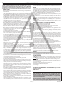 2
2
-
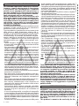 3
3
-
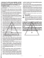 4
4
-
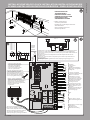 5
5
-
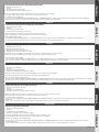 6
6
-
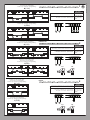 7
7
-
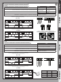 8
8
-
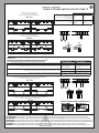 9
9
-
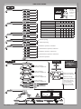 10
10
-
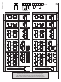 11
11
-
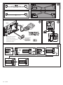 12
12
-
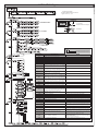 13
13
-
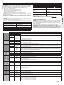 14
14
-
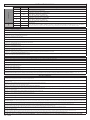 15
15
-
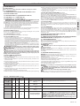 16
16
-
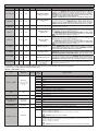 17
17
-
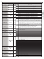 18
18
-
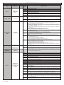 19
19
-
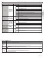 20
20
-
 21
21


in altre lingue
- English: BFT Thalia L User manual
Documenti correlati
-
BFT Thalia P Manuale utente
-
-
-
-
-
-
-
BFT Virgo Smart BT A Manuale utente
-
-
Altri documenti
-
 quiko QK-CE220RL4 Manuale utente
-
 quiko QK-CE220BATRL4 Manuale utente
-
 quiko QK-CE220BATRL4 Manuale utente
-
Bauer Argo Guida d'installazione
-
Genius Edge Istruzioni per l'uso
-
 DTS ECO 500 Guida d'installazione
-
Danfoss TP5001 series Manuale del proprietario
-
 Mighty Mule R4222 Guida d'installazione
-
 Mighty Mule R4222 Istruzioni per l'uso
-
Kenwood NXR-1800 Manuale utente


