


Contents
1.0 Introduction.................................................................................................................................. 1
1.1 Capacities and Resolutions . . . . . . . . . . . . . . . . . . . . . . . . . . . . . . . . . . . . . . . . . . . . . . . . . . . . . . . 1
1.2 Modes of Operation . . . . . . . . . . . . . . . . . . . . . . . . . . . . . . . . . . . . . . . . . . . . . . . . . . . . . . . . . . . . . 2
1.2.1 Description of Modes of Operation . . . . . . . . . . . . . . . . . . . . . . . . . . . . . . . . . . . . . . . . . . . . . . . . . . . . 2
1.3 Keyboard and Display . . . . . . . . . . . . . . . . . . . . . . . . . . . . . . . . . . . . . . . . . . . . . . . . . . . . . . . . . . . 2
1.3.1 Display Specifications . . . . . . . . . . . . . . . . . . . . . . . . . . . . . . . . . . . . . . . . . . . . . . . . . . . . . . . . . . . . . . 2
1.3.2 Indicator Lamps . . . . . . . . . . . . . . . . . . . . . . . . . . . . . . . . . . . . . . . . . . . . . . . . . . . . . . . . . . . . . . . . . . 2
1.3.3 Key Functions . . . . . . . . . . . . . . . . . . . . . . . . . . . . . . . . . . . . . . . . . . . . . . . . . . . . . . . . . . . . . . . . . . . . 3
2.0 Installation ................................................................................................................................... 6
2.1 Unpacking. . . . . . . . . . . . . . . . . . . . . . . . . . . . . . . . . . . . . . . . . . . . . . . . . . . . . . . . . . . . . . . . . . . . . 6
2.2 Repacking. . . . . . . . . . . . . . . . . . . . . . . . . . . . . . . . . . . . . . . . . . . . . . . . . . . . . . . . . . . . . . . . . . . . . 7
2.3 Setting Up. . . . . . . . . . . . . . . . . . . . . . . . . . . . . . . . . . . . . . . . . . . . . . . . . . . . . . . . . . . . . . . . . . . . . 7
2.4 Powering Up the DC-788 . . . . . . . . . . . . . . . . . . . . . . . . . . . . . . . . . . . . . . . . . . . . . . . . . . . . . . . . . 7
2.4.1 AC Power Source . . . . . . . . . . . . . . . . . . . . . . . . . . . . . . . . . . . . . . . . . . . . . . . . . . . . . . . . . . . . . . . . . 7
2.4.2 DC Battery Pack Replacement/Installation. . . . . . . . . . . . . . . . . . . . . . . . . . . . . . . . . . . . . . . . . . . . . . . 8
2.4.3 Battery Charging . . . . . . . . . . . . . . . . . . . . . . . . . . . . . . . . . . . . . . . . . . . . . . . . . . . . . . . . . . . . . . . . . . 9
2.4.4 Start-Up Screens . . . . . . . . . . . . . . . . . . . . . . . . . . . . . . . . . . . . . . . . . . . . . . . . . . . . . . . . . . . . . . . . . 9
2.5 Setting the Date . . . . . . . . . . . . . . . . . . . . . . . . . . . . . . . . . . . . . . . . . . . . . . . . . . . . . . . . . . . . . . . 10
2.6 Replacement Parts. . . . . . . . . . . . . . . . . . . . . . . . . . . . . . . . . . . . . . . . . . . . . . . . . . . . . . . . . . . . . 10
2.7 Block Diagram of Electrical Connections . . . . . . . . . . . . . . . . . . . . . . . . . . . . . . . . . . . . . . . . . . . 11
2.8 Physical Layout of Electrical Connections . . . . . . . . . . . . . . . . . . . . . . . . . . . . . . . . . . . . . . . . . . 11
3.0 Configuration Settings ............................................................................................................... 12
3.1 Configuring Specification 141 and 142 Settings from the Scale Keyboard . . . . . . . . . . . . . . . . 12
3.1.1 Customer Specification (141 Settings) . . . . . . . . . . . . . . . . . . . . . . . . . . . . . . . . . . . . . . . . . . . . . . . . . 12
3.1.2 Weight and Measurement Specifications (142 Settings). . . . . . . . . . . . . . . . . . . . . . . . . . . . . . . . . . . . 15
4.0 Calibration ................................................................................................................................. 19
5.0 Scale Operations........................................................................................................................ 21
5.1 Counting Scale Accuracy and the TEP (Teraoka Error Prediction) Mode . . . . . . . . . . . . . . . . . . 21
5.2 Weight Unit Switching . . . . . . . . . . . . . . . . . . . . . . . . . . . . . . . . . . . . . . . . . . . . . . . . . . . . . . . . . . 22
5.3 Toggling Between Scales . . . . . . . . . . . . . . . . . . . . . . . . . . . . . . . . . . . . . . . . . . . . . . . . . . . . . . . 22
5.4 Setting Tare Weights in Weighing Mode. . . . . . . . . . . . . . . . . . . . . . . . . . . . . . . . . . . . . . . . . . . . 22
5.4.1 One Touch Tare (When the Tare Weight is Unknown) . . . . . . . . . . . . . . . . . . . . . . . . . . . . . . . . . . . . . 22
5.4.2 Digital Tare (When Tare Weight is Known in Advance) . . . . . . . . . . . . . . . . . . . . . . . . . . . . . . . . . . . . . 22
5.4.3 Tare Addition or Subtraction . . . . . . . . . . . . . . . . . . . . . . . . . . . . . . . . . . . . . . . . . . . . . . . . . . . . . . . . 22
5.4.4 Tare Override . . . . . . . . . . . . . . . . . . . . . . . . . . . . . . . . . . . . . . . . . . . . . . . . . . . . . . . . . . . . . . . . . . . 23
5.5 Entering Unit Weights . . . . . . . . . . . . . . . . . . . . . . . . . . . . . . . . . . . . . . . . . . . . . . . . . . . . . . . . . . 23
5.5.1 Unit Weight Operation by Sampling. . . . . . . . . . . . . . . . . . . . . . . . . . . . . . . . . . . . . . . . . . . . . . . . . . . 23
5.5.2 Unit Weight Operation by Key Entry. . . . . . . . . . . . . . . . . . . . . . . . . . . . . . . . . . . . . . . . . . . . . . . . . . . 24
5.6 Setting a Lot Number . . . . . . . . . . . . . . . . . . . . . . . . . . . . . . . . . . . . . . . . . . . . . . . . . . . . . . . . . . . 24
5.7 Setting a Sequence Number . . . . . . . . . . . . . . . . . . . . . . . . . . . . . . . . . . . . . . . . . . . . . . . . . . . . . 24
5.8 Operations Without Recalling an Item Code . . . . . . . . . . . . . . . . . . . . . . . . . . . . . . . . . . . . . . . . 25
5.8.1 A Single Counting Operation - Without Recalling an Item Code . . . . . . . . . . . . . . . . . . . . . . . . . . . . . . 25
5.8.2 Part Accumulation or Subtraction and Negative Counting - Without Recalling an Item Code . . . . . . . . 25
5.8.3 Setting a Temporary Lot Number, Part Number or Part Name - Without Recalling an Item Code. . . . . 27
5.9 Using Item Codes in Weighing Mode . . . . . . . . . . . . . . . . . . . . . . . . . . . . . . . . . . . . . . . . . . . . . . 28
5.9.1 Recalling Item Codes using Item Code Number . . . . . . . . . . . . . . . . . . . . . . . . . . . . . . . . . . . . . . . . . 28
5.9.2 View Item Information . . . . . . . . . . . . . . . . . . . . . . . . . . . . . . . . . . . . . . . . . . . . . . . . . . . . . . . . . . . . . 28
5.9.3 Adding Parts To and Subtracting Parts From Inventory . . . . . . . . . . . . . . . . . . . . . . . . . . . . . . . . . . . 28
5.9.4 Tare Override . . . . . . . . . . . . . . . . . . . . . . . . . . . . . . . . . . . . . . . . . . . . . . . . . . . . . . . . . . . . . . . . . . . 30
5.9.5 Delete Item Memory . . . . . . . . . . . . . . . . . . . . . . . . . . . . . . . . . . . . . . . . . . . . . . . . . . . . . . . . . . . . . . 30

6.0 Scale Programming................................................................................................................... 31
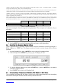
6.1 Checking Memory Status . . . . . . . . . . . . . . . . . . . . . . . . . . . . . . . . . . . . . . . . . . . . . . . . . . . . . . . 31
6.2 Review the Item Code Numbers Programmed in Memory . . . . . . . . . . . . . . . . . . . . . . . . . . . . . 32
6.3 Program Item Code, Tare Weight, Unit Weight, Inventory, Part Number, Part Name, Lot Number,
Setpoint 1 and Setpoint 2 32
6.4 View Item Code Programming in Memory . . . . . . . . . . . . . . . . . . . . . . . . . . . . . . . . . . . . . . . . . . 34
6.5 Program a General Setpoint . . . . . . . . . . . . . . . . . . . . . . . . . . . . . . . . . . . . . . . . . . . . . . . . . . . . . 34
6.6 Resetting the Sequence Number to Zero. . . . . . . . . . . . . . . . . . . . . . . . . . . . . . . . . . . . . . . . . . . 35
6.7 Programming a Temporary Lot Number, Part Number or Part Name . . . . . . . . . . . . . . . . . . . . 35
6.7.1 Change the Lot Number Temporarily . . . . . . . . . . . . . . . . . . . . . . . . . . . . . . . . . . . . . . . . . . . . . . . . . 36
6.7.2 Change the Part Number Temporarily. . . . . . . . . . . . . . . . . . . . . . . . . . . . . . . . . . . . . . . . . . . . . . . . . 36
6.7.3 Change the Part Name Temporarily . . . . . . . . . . . . . . . . . . . . . . . . . . . . . . . . . . . . . . . . . . . . . . . . . . 36
6.8 Delete Item Memory . . . . . . . . . . . . . . . . . . . . . . . . . . . . . . . . . . . . . . . . . . . . . . . . . . . . . . . . . . . 36
6.8.1 Delete All Item Codes in Memory . . . . . . . . . . . . . . . . . . . . . . . . . . . . . . . . . . . . . . . . . . . . . . . . . . . . 36
6.8.2 Delete a Specific Item Code . . . . . . . . . . . . . . . . . . . . . . . . . . . . . . . . . . . . . . . . . . . . . . . . . . . . . . . . 36
6.8.3 Delete All Inventory Values from Memory. . . . . . . . . . . . . . . . . . . . . . . . . . . . . . . . . . . . . . . . . . . . . . . 37
6.8.4 Delete All Unit Weight Values from Memory. . . . . . . . . . . . . . . . . . . . . . . . . . . . . . . . . . . . . . . . . . . . . 37
6.8.5 Delete All Tare Weight Values From Memory. . . . . . . . . . . . . . . . . . . . . . . . . . . . . . . . . . . . . . . . . . . . 38
6.8.6 Delete all Part Numbers From Memory . . . . . . . . . . . . . . . . . . . . . . . . . . . . . . . . . . . . . . . . . . . . . . . . 38
6.8.7 Delete All Setpoint Data in Memory . . . . . . . . . . . . . . . . . . . . . . . . . . . . . . . . . . . . . . . . . . . . . . . . . . . 39
6.8.8 Delete All Part Names in Memory . . . . . . . . . . . . . . . . . . . . . . . . . . . . . . . . . . . . . . . . . . . . . . . . . . . . 39
7.0 External Devices: Printers, PCs and Scales.............................................................................. 41
7.1 Printer Connection . . . . . . . . . . . . . . . . . . . . . . . . . . . . . . . . . . . . . . . . . . . . . . . . . . . . . . . . . . . . 41
7.1.1 Zebra LP2844. . . . . . . . . . . . . . . . . . . . . . . . . . . . . . . . . . . . . . . . . . . . . . . . . . . . . . . . . . . . . . . . . . . 41
7.1.2 DIGI GP460R . . . . . . . . . . . . . . . . . . . . . . . . . . . . . . . . . . . . . . . . . . . . . . . . . . . . . . . . . . . . . . . . . . . 41
7.1.3 Epson TM-U210 and TM-U290, Star SP2320 and SP298 . . . . . . . . . . . . . . . . . . . . . . . . . . . . . . . . . 42
7.2 Printer Label Formats . . . . . . . . . . . . . . . . . . . . . . . . . . . . . . . . . . . . . . . . . . . . . . . . . . . . . . . . . . 42
7.2.1 No Printer . . . . . . . . . . . . . . . . . . . . . . . . . . . . . . . . . . . . . . . . . . . . . . . . . . . . . . . . . . . . . . . . . . . . . . 42
7.2.2 DIGI GP460R Label Printer . . . . . . . . . . . . . . . . . . . . . . . . . . . . . . . . . . . . . . . . . . . . . . . . . . . . . . . . . 42
7.2.3 ZEBRA LP2844 Barcode Printer . . . . . . . . . . . . . . . . . . . . . . . . . . . . . . . . . . . . . . . . . . . . . . . . . . . . . 42
7.2.4 Epson TMU200 or Star SP2320 Tape Printer . . . . . . . . . . . . . . . . . . . . . . . . . . . . . . . . . . . . . . . . . . . 44
7.2.5 Epson TM-U295 or Star SP298 Ticket Printers . . . . . . . . . . . . . . . . . . . . . . . . . . . . . . . . . . . . . . . . . . 44
7.2.6 DIGI TVP1000 Barcode Printer . . . . . . . . . . . . . . . . . . . . . . . . . . . . . . . . . . . . . . . . . . . . . . . . . . . . . . 44
7.3 Connecting to a PC . . . . . . . . . . . . . . . . . . . . . . . . . . . . . . . . . . . . . . . . . . . . . . . . . . . . . . . . . . . . 45
7.3.1 Setting the Scale Specifications for Communication to a PC. . . . . . . . . . . . . . . . . . . . . . . . . . . . . . . . 45
7.3.2 Communication Method . . . . . . . . . . . . . . . . . . . . . . . . . . . . . . . . . . . . . . . . . . . . . . . . . . . . . . . . . . . 45
7.3.3 Pin Assignments . . . . . . . . . . . . . . . . . . . . . . . . . . . . . . . . . . . . . . . . . . . . . . . . . . . . . . . . . . . . . . . . . 48
7.3.4 Characters That Can Be Transmitted by RS-232C . . . . . . . . . . . . . . . . . . . . . . . . . . . . . . . . . . . . . . . 48
7.3.5 RS-232C Data Transmission Formats . . . . . . . . . . . . . . . . . . . . . . . . . . . . . . . . . . . . . . . . . . . . . . . . . 49
7.4 Remote Scale Channel . . . . . . . . . . . . . . . . . . . . . . . . . . . . . . . . . . . . . . . . . . . . . . . . . . . . . . . . . 51
7.4.1 Setting the Specifications for Scale 2 . . . . . . . . . . . . . . . . . . . . . . . . . . . . . . . . . . . . . . . . . . . . . . . . . 52
7.4.2 Remote Platforms Available . . . . . . . . . . . . . . . . . . . . . . . . . . . . . . . . . . . . . . . . . . . . . . . . . . . . . . . . 53
8.0 Appendix .................................................................................................................................... 54
8.1 DC-788 Specifications. . . . . . . . . . . . . . . . . . . . . . . . . . . . . . . . . . . . . . . . . . . . . . . . . . . . . . . . . . 54
8.2 DC-788 Error Message List. . . . . . . . . . . . . . . . . . . . . . . . . . . . . . . . . . . . . . . . . . . . . . . . . . . . . . 54
8.3 ASCII Code Table . . . . . . . . . . . . . . . . . . . . . . . . . . . . . . . . . . . . . . . . . . . . . . . . . . . . . . . . . . . . . 55
9.0 DC-788 Limited Warranty........................................................................................................... 57
5FDIOJDBMUSBJOJOHTFNJOBSTBSFBWBJMBCMFUISPVHI3JDF-BLF8FJHIJOH4ZTUFNT
$PVSTFEFTDSJQUJPOTBOEEBUFTDBOCFWJFXFEBUXXXSJDFMBLFDPNPSPCUBJOFE
CZDBMMJOHBOEBTLJOHGPSUIFUSBJOJOHEFQBSUNFOU
© 2007 Rice Lake Weighing Systems. All rights reserved. Printed in the United States of America.
Specifications subject to change without notice.
Version 1.09, July 2007

Introduction 1
About This Manual
This manual contains operating procedures for the DC-788 counting scale and provides the user with all the
information necessary for setup and operation. It is organized based on the procedures you will likely follow
when setting up and using your counting scale. This manual applies to Version 1.09 of the DC-788 counting scale
series.
Some procedures described in this manual require work inside the scale base. These procedures are to
be performed by qualified service personnel only.
Authorized distributors and their employees can view or download this manual from the
DIGI distributor site at www.DigiScales.com.
1.0 Introduction
The DC-788 is a low cost counting scale that offers practical solutions for a full range of counting applications.
Its counting resolution of 1/1,000,000 gives you maximum counting precision and accuracy. Its high-visibility
red LCD display enables operators to easily see weights and quantities. With the ability to store an item code,
part number, part name, lot number, tare weight, unit weight, inventory quantity and setpoint value for 100 of
your pieces, parts, or items, the DC-788 is a self-contained inventory system. The RS-232 output allows you to
connect to a printer or PC, while the remote scale channel lets you add another weighing platform. When
portability is required, choose the battery operation option of the DC-788 for over 24 hours of continuous use in
mobile workstations, outdoor applications, and rental fleets. It’s waterproof keyboard and splash-proof housing
make the DC-788 rugged enough to operate reliably in many environments and withstand transport from one
area of the plant to another or from one business to the next.
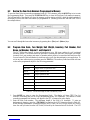
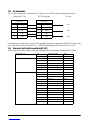
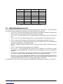
1.1 Capacities and Resolutions
Table 1-1 lists the scale capacities, minimum graduations, and tare ranges for all models of the DC-788 counting
scales. The display resolution is 1/10,000 with an internal or counting resolution of 1/1,000,000. Units are
selectable from lb to kg from the keyboard.
DC-788 Single Scale
#AUTION
DC-788 Capacity Minimum Graduation Ta re R a nge
500 g 0.1 g (1e = 200IR) 0-249.9 g
1 kg 0.2 g (1e = 200IR) 0 - 0.4998 kg
2.5 kg 0.5 g (1e = 200IR) 0 - 0.9995 kg
5 kg 1 g (1e = 200IR) 0 - 2.499 kg
10 kg 2 g (1e = 200IR 0 - 9.998 kg
25 kg 5 g (1e = 200IR 0 - 9.995 kg
1 lb 0.0001 lb (1e = 100IR) 0 - 0.9998 lb
2 lb 0.0002 lb (1e = 100IR) 0 - 0.0095 lb
5 lb 0.0005 lb (1e = 100IR) 0 - 9.995 lb
10 lb 0.001 lb (1e = 100IR) 0 - 9.999 lb
20 lb 0.002 lb (1e = 100IR) 0 - 9.998 lb
50 lb 0.005 lb (1e = 100IR) 0 - 9.995 lb
Table 1-1. DC-788 Capacities, Minimum Graduations and Tare Ranges

2DC-788 Operation Manual
1.2 Modes of Operation
1.2.1 Description of Modes of Operation
The DC-788 has three modes of operation:
• Weighing Mode – where all weighing, counting and printing operations take place.
• Programming Mode – where item and inventory data can be programmed into the memory of the scale.
The display will show ProG to indicate that you are the Programming Mode.
• Maintenance Mode - where your DIGI dealer can set specifications, perform scale calibration and
other maintenance functions.
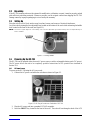
1.3 Keyboard and Display
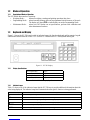
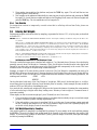
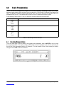
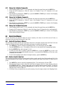
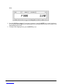
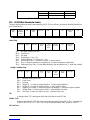
Figure 1-1 shows the DC-788 console with its indicator lamps, the function keyboard and the numeric keypad.
Annunciators are described in Section 1.3.2. Section 1.3.3 describes the DC-788 keyboard and keypad.
Figure 1-1. DC-788 Display
1.3.1 Display Specifications
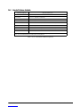
1.3.2 Indicator Lamps
Table 1-3 shows a list of the indicator lamps that the DC-788 uses to provide additional information about the
value being displayed. The indicator lamps are illuminated when the specific function is being performed.
Tare weight display 5 digits
Weight display 5 digits
Unit weight display 5 digits
Quantity display 7 digits
Table 1-2. DC-788 Display Specifications
Indicator Lamp Function or Meaning
0 On when the gross weight is zero and is stable
NET On when the display shows net weight (when a tare weight is entered or recalled)
KG On when the item is being weighed in kg units with [kg/lb] key pressed
LB On when the item is being weighed in lb units with [kg/lb] key pressed
RECOMP On when unit weight recomputing is possible
INSUFF On when the net weight is below the specified percentage of scale capacity
Table 1-3. DC-788 Indicator Lamps and Function

Introduction 3
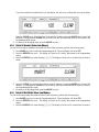
1.3.3 Key Functions
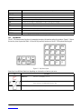
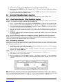
The DC-788 features many functions for managing inventory information and scale operation. Figure 1-2 shows
the two key-sheet layouts and Table 1-4 lists the keys and key functions of the DC-788 keyboard and keypad.
Figure 1-2. Key Sheet Layout
Some keys have different functions depending on what mode or function you are in.
scale 1 On when scale 1 is in use (the built-in platform)
scale 2 On when scale 2 is in use (an external platform)
prog On when the scale is in Programming Mode
wt/1000 On when the unit weight is being displayed per 1000 pcs.
apw On when the unit weight is displayed per one piece (average piece weight).
∑Quantity is accumulating
out Item out of item inventory (subtracting from inventory)
in Item in to item inventory (adding to inventory)
batt Battery warning when weak and needs charging (only for rechargeable battery type)
charge Battery charging (only for rechargeable battery type)
Key Description
ON/OFF - Turns the scale display on or off
Numeric keys - Used to enter numeric values. When using the scale, first enter a numeric
value, then press the appropriate function key.
DECIMAL key - Used to set the decimal point.
Table 1-4. DC-788 Key Functions
Indicator Lamp Function or Meaning
Table 1-3. DC-788 Indicator Lamps and Function
to

4DC-788 Operation Manual
CLEAR key.
Weighing Mode - Used to clear the Unit Weight. Used to return to the weighing display when
doing accumulation.
Programming Mode - Used to delete an Item Code or associated value when programming item
codes. Used to Cancel input in programming SPC codes. Used to Reset
Sequence Number to zero when programming Sequence Codes.
PCS key - Used for computing unit weight by sampling.
TARE key.
Weighing Mode - Used to set or clear the tare value.
Programming Mode - Used to store SPC changes and escape to the Weighing Mode when
programming specifications.
Maintenance Mode - Used to escape to the Weighing Mode from the Maintenance Mode.
REZERO key.
Weighing Mode - Used to reset the weight display to zero.
Maintenance Mode - Used to enter different parts of the Maintenance Mode when combined with
numeric codes.
CODE/IN-OUT key.
Weighing Mode - Used to recall Item Codes from memory and to determine inventory IN/OUT
status.
- (Minus) key.
Weighing Mode - Used to delete a character entered during operations. Used to subtract a
quantity during accumulation. Also prompts printing of a label if an external
printer is connected.
Programming Mode - Used to navigate to the previous specification when programming SPC
codes. Used to move between item codes when reviewing already
programmed item codes. Used to display the current date and time when
programming the date and time.
+ (Plus) key.
Weighing Mode - Used to accumulate data. Also prompts printing of a label if an external
printer is connected.
Programming Mode - Used to navigate to the next specification when programming SPC codes.
Used to move between item codes when reviewing already programmed
item codes. Used to store set point data when programming item codes.
* PRINT key -Print/Data setting key.
Weighing Mode - Used to print a label when an external printer is connected. Used to clear
TOTAL data when doing accumulation.
Programming Mode - Used to temporarily store changes to specification data when programming
SPCs. Used to store data to Item Code memory when programming Item
Codes. Used to store changes to item codes when editing Item Code
information. Used to store the date and time when programming Date and
Time.
SCALE key. Used to select between Scale 1 and Scale 2 if an external scale is
connected.
MODE key - Used to enter the programming mode from the weighing mode. Used to
enter the command mode when using numeric commands.
Key Description
Table 1-4. DC-788 Key Functions

Introduction 5
KG/LB/INVENT key- Used to convert the weighing units between kg and lb. Also used to toggle
on and off whether inventory stored in memory is being affected by the
current transaction.
UNIT WEIGHT key - Used to set the unit weight and display all digits of the unit weight.
Key Description
Table 1-4. DC-788 Key Functions

6DC-788 Operation Manual
2.0 Installation
This section describes the procedure for the installation and setup of the DC-788 counting scale.
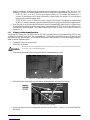
2.1 Unpacking
Do not turn scale upside down. Always work with scale on its side! Damage to the load cell can occur if
the scale is turned upside down.
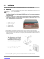
1. Immediately after unpacking, visually inspect the DC-788 counting scale to ensure all components are
included and undamaged. If any were damaged in shipment, notify Rice Lake Weighing Systems and the
shipper immediately.
2. The DC-788 counting scale is carefully packed for protection during shipping. After opening the box,
remove all the components. Check the insides of the box carefully to make sure you have all of the
pieces. The package should include the following:
• DC-788 counting scale
• Stainless steel platter
• AC power cord
• Operation Manual
3. Remove the bag protecting the scale and the protective film covering the front panel and platter.
4. Seat the stainless steel platter on the platter supports, with the four corner pins inserted into the corner
rubber stops. For DC-788 scales with a 2 lb. capacity, the scale must first be unlocked using the
following procedure.
• Take off the two Nuts A and Screw C.
Then remove Screws D, Plate C and Nut
B. Then turn the scale on its side to
complete removal of the locking screw.
REMINDER: Do not turn the scale upside
down as this can damage the load cells.
• Remove Nut F and then Screw E. Then
take off Screw G and Washer H.
5. After ensuring that all parts are present, store the DC-788 scale box for possible future use.
#AUTION

Installation 7
2.2 Repacking
If the DC-788 counting scale must be returned for modification, calibration or repair, it must be properly packed
with sufficient cushioning materials. Whenever possible, use the original carton when shipping the DC-788.
Damage caused by improper packaging is not covered by the warranty.
2.3 Setting Up
Place the scale on a solid, level surface away from fans, breezes, and sources of electrical interference.
Level the scale by turning the four adjustable legs located on the bottom of the scale while referencing the bubble
level located on the front of the scale (see Figure 2-1).
NOTE: To ensure a higher degree of scale stability, turn in all four adjustable legs before leveling. Turn out adjustable legs to
level as needed.
Figure 2-1. Leveling Bubble
2.4 Powering Up the DC-788
The DC-788 can be operated either from an AC power source or with a rechargeable battery pack (DC power).
The DC power allows the unit to be completely portable. Instructions for DC operation are contained in
Section 2.4.2.
2.4.1 AC Power Source
To power up the DC-788 using the AC power cord:
1. Connect the AC power cord under the scale base as shown in Figure 2-2.
Figure 2-2. AC Plug-in Location on Underside of DC-788
2. Plug the AC power cord into a grounded 115 VAC receptacle.
3. Press the ON/OFF key located on the front of the scale. The scale will run through a check of the LCD

8DC-788 Operation Manual
display’s segments. How thorough the segment check is depends on the setting of SPC 20, Bit 2. The
default is 1: Normal (For further instructions on how to set the scale’s specifications, see Section 3.1.2):
• If SPC 20, Bit 2 is set to 0: Fast, the scale display’s 888’s for 1.5 seconds, then blanks for 1.5
seconds. It then displays 888’s again followed by a blank display for another 1.5 seconds before
going into the normal weighing mode.
• If SPC 20, Bit 2 is set to 1: Normal, the scale’s display will test the LCD segments for each numeral
from 0 to 9, asterisks, decimal points and annunciators before going into the normal weighing mode.
4. Once the scale is on, the time interval before the scale will automatically power itself off, if there no key
is pressed and no weight is placed on the platter, is determined by SPC 00- Auto Power-Off Function.
The default is 0000: Disabled. (For further instructions on how to set the scale’s specifications, see
Section 3.1.1)
2.4.2 DC Battery Pack Replacement/Installation
An optional DC battery pack (PN 88933) for the DC-788 is available and can be purchased from RLWS to ship
with the scale or retrofit in the field. The rechargeable 6V 5.0 AH battery pack allows for up to 24 hours of scale
use without an AC power supply. It is located in the bottom of the scale base. Use the following procedure to
install or replace the battery pack.
1. Unplug the scale from power source.
2. Place scale its left side.
Do not turn the scale upside down. Always work with the scale on its side. Damage to the load cell can
occur if the scale is turned upside down.
3. Unscrew the two thumb screws holding the battery compartment door closed.
Figure 2-3. Thumb Screws for Battery Compartment
4. Unscrew the two screws holding on the battery holding bracket and remove the bracket.
Figure 2-4. Removing Battery Bracket.
5. Remove the battery from its compartment, then disconnect the black (-) and red (+) electrical leads from
the battery.
#AUTION

Installation 9
6. Attach the red lead to the positive (+) terminal of the new DC battery pack, and the black lead to the
negative (-) terminal. Place new DC battery pack in battery compartment.
7. Replace the battery holding bracket and fasten it with its two screws.
8. Replace the battery compartment door and fasten it with its two thumb screws.
9. Put the scale back upright on its feet.
10. Press the ON/OFF key located on the front of the scale. The scale will run through a check of the LCD
display’s segments. How thorough the segment check is depends on the setting of SPC 20, Bit 2. The
default is 1: Normal (For further instructions on how to set the scale’s specifications, see Section 3.1.2):
• If SPC 20, Bit 2 is set to 0: Fast, the scale display’s 888’s for 1.5 seconds, then blanks for 1.5
seconds. It then displays 888’s again followed by a blank display for another 1.5 seconds before
going into the normal weighing mode.
• If SPC 20, Bit 2 is set to 1: Normal, the scale’s display will test the LCD segments for each numeral
from 0 to 9, asterisks, decimal points and annunciators before going into the normal weighing mode.
2.4.3 Battery Charging
A fully charged battery allows for approximately 24 hours of continuous use. When the battery is low the battery
indicator light will light up. It will take approximately 8-10 hours to fully recharge a battery that has been
completely dissipated. To charge the battery, plug in the AC power cord.
2.4.4 Start-Up Screens
1. If SPC 20, Bit 3 - Version Display When Power On is set to 0: Allow, the scale will display the current
version of the firmware it is using as it powers up (For further instructions on how to set the
specifications, see Section 3.1.2).
2. After a test of the different elements of the display, the scale takes you to the stand-by screen in the
Weighing Mode. SPC 20, Bit 2 - Selection of Segment-Check Style controls whether the startup test of
the segments is Fast or Standard. At the stand-by screen the TARE, WEIGHT, UNIT WEIGHT and PCS
displays show zeroes.
From this stand-by screen all of the basic weighing, counting and inventory operations can be performed
3. If there is anything on the platform(s) and it exceeds the scale start range, the display will show the error
message OF indicating “weight overflow”.
Note: The Initial Start Range settings are controlled by SPC 20, Bit 1. The default setting is 0: ± 10% OF FULL SCALE.
If this error appears, remove the weight from the platform and the scale will continue its startup
sequence.

10 DC-788 Operation Manual
2.5 Setting the Date
Without a power supply, the DC-788 will reset the time and date. For units that do have battery power, the time
and date can be supported for up to 20 days in the OFF status without any AC power supply. After 20 days the
unit will reset itself.
The procedure below can also be used to adjust the time when moving from Standard to Daylight Savings Time
or when the scale is moved to a new facility in a different time zone.
NOTE: SPC 04, Bits 3 and 2 - ORDER OF MONTH, DATE AND YEAR allows you to set the format for the date that you prefer
the scale to display. The default is 00: Month/Date/Year. To change these specifications, see Section 3.1.2).
1. Press the MODE key twice until the display shows ProG.
2. Press the – (Minus) key to display the current time and date.
3. Press the – (Minus) key again.
4. Using the keyboard, enter the desired date i.e.: [0] [6] [0] [9] [0] [5] for June 9th, 2005.
5. Press the * PRINT key to store the date setting.
6. Using the keyboard, enter the time, i.e.: [1] [5] [0] [5]
7. Press the * PRINT key to store the time setting
8. Press the MODE key to exit the weighing mode.
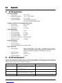
2.6 Replacement Parts
The following list contains the part numbers and descriptions of replacement parts available for the DC-788
counting scale.
RLWS Part Number Description
88933 Battery Pack, 6 V, 5.0AH lead acid
89994 Keysheet, 16 keys, DC-788
89997 Keysheet, 8 keys, DC-788
89999 Keyboard
90152 Mainboard for DC-788
90153 Loadcell, 2 lb
90154 Loadcell, 10 lbs
90155 Loadcell, 20 lbs
90156 Loadcell, 50 lbs
90157 Loadcell, 100 lbs
90188 Top co ver
90160 Support platter
90171 Platter cover, 10 lb to 100 lb
65956 Platter cover, 2 lb
Table 2-1. DC-788 Replacement Parts

Installation 11
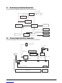
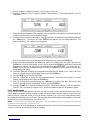
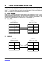
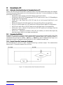
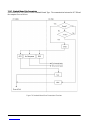
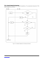
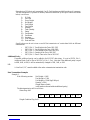
2.7 Block Diagram of Electrical Connections
The following block diagram illustrates the electrical connections.
2.8 Physical Layout of Electrical Connections
The following diagram illustrates the actual layout of electrical connections.
1PXFS4FMFDUPS 3FHVMBUPS
5SBOTGPSNFS
$IBSHF$POUSPMMFS
3FDIBSHBCMF
#BUUFSZ7PIN
.JDSPDPOUSPMMFS
)4FSJFT -$%.PEVMF
34$
*OUFSGBDF
-PBEDFMM
-PBEDFMM
"%$POWFSUPS
,FZQBE
&FQSPN$
7"%
7
-PBEDFMM
3FDIBSHBCMF#BUUFSZ
70IN 5SBOTGPSNFS
"$3FDFQUBDMF
0QFSBUPS-$% ,FZCPBSE
45#
$/
34
*OUFSGBDF
$/
$/
"%#PBSE
45#
$/ $/ $/
1
1
1
1 1
1
%$.BJO#PBSE45#
'VTF
"7
185
1JO'FNBMF"NQIFOPM
GPS&YUFSOBM-PBEDFMM
4$8%

12 DC-788 Operation Manual
3.0 Configuration Settings
This section presents the setup and configuration of the DC-788 counting scale to be used specifically by
distributors and service technicians. Configuring these specifications allow you to tailor the DC-788 to your
specific applications.
Setting the specifications allows you to modify the functionality of the DC-788. Use the tables in this section to
view the options you can modify.
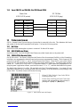
3.1 Configuring Specification 141 and 142 Settings from the Scale Keyboard
The following tables list the DC-788 specifications, their corresponding default values, and the other possible
values to which they can be programmed. The default values are set at the factory when the scale is shipped.
SPC 0 through SPC 19 (Table 3-1) are customer specifications and use the 141 access code, while SPC 20
through SPC 35 (Table 3-2) are weight and measurement specifications, and use the 142 access code
In programming specifications, the + (Plus) and – (Minus) keys allow you to move to the next or previous
specification. The CLEAR key cancels any input you have made. The * PRINT key temporarily stores to
memory any changes you have made. The TARE key saves to memory the changes you have made and returns
you to the weighing mode. Note also that when programming specifications, only the 0 and 1 keys on the
numeric keypad are enabled, since those are the only valid entries.
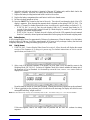
3.1.1 Customer Specification (141 Settings)
1. To configure customer specifications, press and hold the REZERO key and enter 141 using the numeric
keypad. The first SPC code is displayed.
The Weight display shows what specification you are in (in this case, SPC00). The Unit Weight display
shows how this specification is currently programmed (Bit 3 = 0; Bit 2 = 0; Bit 1 = 0, and Bit 0 = 1 in this
example, while the PCS display will show any changes you enter.
If this is the SPC that you want to modify, enter the new setting from the numeric keypad and press the *
PRINT key to enter the change into temporary memory and move to the next SPC code.
2. Use the + (plus) and – (minus) keys to scroll through the specifications until you find the one you want.
Then make your changes per the instructions in Step 1.
3. To change another SPC code before exiting, repeat Steps 1 and 2.
4. To save all the changed SPC settings currently in temporary memory and exit to the Weighing Mode,
press the TARE key.

Configuration Settings 13
SPEC No. Bit 3 Bit 2 Bit 1 Bit 0
00 Auto Power-off Function (for no key operation and weighing operation)
0000: Auto power-off disable when scale is not in use (DEFAULT)
0001: 3 minutes
0010: 10 minutes
0011: 30 minutes
1011: 1 hour
0101: 3 hours
0110 ~ 1111 - not used
(SP1_OFFT)
01 0: Not used
02 Buzzer
0: On (DEFAULT)
1: Off
(SP1_BUZZ)
Error Alarm
0: On (DEFAULT)
1: Off
(SP1_ALARM)
Set Point Alarm
0: On (DEFAULT)
1: Off
(SP1_PALARM)
Not Used
0: (DEFAULT)
03 Unit weight base per
1000PCS or 1 PCS
display
0: 1000PCS (DEFAULT)
1: 1PCS
(SP1_UWID)
Note: When SPEC 27 -
Gross Mode is set to 0:
Allow, the scale remains in
UW/1000, regardless of
how this SPEC 3 is set.
See note under SPEC 27.
Sampling time for unit
weight calculation
0: 10 times
1: 5 times (DEFAULT)
(SP1_STFUWC)
Negative Counting
0: Allow (DEFAULT)
1: Inhibit
(SP1_NCOUNT)
Re-zero Function
0: Allow (DEFAULT)
1: Inhibit
(SP_RZF)
04 Order of month, date and year
00: MM/DD/YY (DEFAULT)
01: DD/MM/YY
10: YY/MM/DD
11: Not used
(SP1_DATEO)
Set Point Type
00: % quantity (DEFAULT)
01: % weight
10: Quantity
11: Weight
(SP1_SPT)
05 Function of RS-232 Interface
00: PC
01: Printer (DEFAULT)
10: Not used
11: Not used
(SP1_RS232IF)
Extrent of insufficient samples
00: 0.1% (DEFAULT)
01: 0.2%
10: 0.0%
11: Not used
(SP1_INSUFFRG)
06 RTS/CTS Handshaking of
RS-232C
0: On
1: Off (DEFAULT)
(SP1_RTS)
Baud Rate of RS-232C
000: 1200 bps 100: 19200 bps
001: 2400 bps 101: Not used
010: 4800 bps 110: Not used
011: 9600 bps (DEFAULT) 111: Not used
(SP1_BAUD)
07 Stop bit of RS-232C
0: 1 bit (DEFAULT)
1: 2 bit
(SP1_STOP)
Data length of RS-232C
0: 7 bit
1: 8 bit (DEFAULT)
(SP1_DLEN)
Parity of RS-232C
00: None (DEFAULT) 10: Even
01: Odd 11: Not used
(SP1_PAR)
Table 3-1. DC-788 (141) Settings

14 DC-788 Operation Manual
08 RS-232C PC Protocol
0000: Inhibit data transfer (DEFAULT)
0001: Standard stream type (continuous output
0010: Standard manual type
0011: Stand command type
0100~ 1111: Not used
(SP1MODE)
09 External Printer Type
0000: No Printer (DEFAULT)
0001: DIGI GP460R Label Printer
0010: Zebra LP2844 Bar Code Printer
0011: Epson TMU200 or Star SP2320 Tape Printers
0100: Epson TM295 or Star SP298 Ticket Printers
0101: TVP1000 Bar Code Printer
(SP1PRINTER)
10 Interval of Time Out Error of RS-232
00: 1 Second
01: 3 Seconds (DEFAULT)
10: 5 Seconds
11: 10 Seconds
(SP1TIME)
Transmission Condition
of RS-232
0: Weight Stable (DEFAULT)
1: Unconditional
(SP1_COND)
Additional Parity Code in
Te xt o f RS-2 3 2
0: No (DEFAULT)
1: Yes
(SP1_APAR)
11 Tare Weight in Text of
RS-232
0: No
1: Yes (DEFAULT)
(SP1_TW)
Unit Weight in Text of
RS-232
0: No
1: Yes (DEFAULT)
(SP1_UW)
Gross Weight in Text of
RS-232
0: No
1: Yes (DEFAULT)
(SP1_GW)
Quantity in Text of
RS-232
0: No
1: Yes (DEFAULT)
(SP1_TP)
12 Date & Time in Text of
RS-232
0: No
1: Yes (DEFAULT)
(SP1_DTIME)
Parts Information in Text
of RS-232:
0: Include Parts Information
1: Include Only ID Code
(Output like DC-180.
Requires a setpoint value to
be entered to work)
Header Code in Text of
RS-232
0: No
1: Yes (DEFAULT)
(SP1_HEAD)
Weight Range of Data
Output
0: Always (DEFAULT)
1: Over 20e
(SP1_MINWTL)
13 Print When Pressing the +
or - Key
0: No (DEFAULT)
1: Yes
(SP1_PRTK) (*V1.09)
External Printer Print Format
000: Default Format (DEFAULT)
001: Customer Format 1
010: Customer Format 2
~
111: Customer Format 7
(SP1PRINTER)
SPEC No. Bit 3 Bit 2 Bit 1 Bit 0
Table 3-1. DC-788 (141) Settings

Configuration Settings 15
3.1.2 Weight and Measurement Specifications (142 Settings)
To make changes to the Weight and Measurement Specifications, the span switch must be on. (For instructions
on how to turn the span switch on, see Section 4.0.)
1. To configure customer specifications, press and hold the REZERO key and enter 142 using the numeric
keypad. The first SPC code is displayed.
The Weight display shows what specification you are in (in this case, SPC20). The Unit Weight display
shows how this specification is currently programmed (Bit 3 = 1; Bit 2 = 0; Bit 1 = 0, and Bit 0 = 0),
while the PCS display will show any changes you enter.
If this is the SPC that you want to modify, enter the new setting from the numeric keypad and press the *
PRINT key to enter the change into temporary memory and move to the next SPC code.
2. Use the + (Plus) and – (Minus) keys to scroll through the specifications until you find the one you want.
Then make your changes per the instructions in Step 1.
3. To change another SPC code before exiting, repeat Steps 1 and 2.
4. To save all the changed SPC settings currently in temporary memory and exit to the Weighing Mode,
press the TARE key.
14 Clear Unit Weight When
Swap Scale
0: No (DEFAULT)
1: Yes
(SP1_UC) (*V1.06)
Rezero When Swap Scale
0: No (DEFAULT)
1: Yes
(SP1_RZ) (*V.106)
Auto Scale Switching
0: No (DEFAULT)
1: Yes
(SP1_ASS) (*V1.07)
Zero Display
0: Display 0 With ‘/’
1: Display 0 Without ‘/’
(DEFAULT)
(SP1_DIS0) (*V1.10)
15 Display “MEM EXIST”
message reminding you
that there is an
accumulation in memory
0: No
1: Yes (DEFAULT)
(SP1_MEXIST) (V1.10)
Clear TARE Weight When
Swapping Scales
0: No (DEFAULT)
1: Yes
Scale Number in Text of
RS-232
0: No
1: Yes (DEFAULT)
Number of Setpoints
0: 2 Setpoints (Default)
1: 3 Setpoints
(SP1_SPN) (v1.10)
16 - 19 Not Used
SPEC No. Bit 3 Bit 2 Bit 1 Bit 0
Table 3-1. DC-788 (141) Settings

16 DC-788 Operation Manual
SPEC No. Bit 3 Bit 2 Bit 1 Bit 0
20 Version Display When
Power On
0: Allow (DEFAULT)
1: Inhibit
(SP_VER)
Selection of
Segment-Check Style
0: Fast (DEFAULT)
1: Standard
(SP_SEGCK)
Start Range
00: ±10% of Full Scale (DEFAULT)
01: ± 5% of Full Scale
10: ± 3% of Full Scale
11: ± 2% of Full Scale
(SPSRANGE)
21 Minimum Display (Scale 1)
00: 1
01: 2 (DEFAULT)
10: 5
11: 10
(SPMINID)
Minimum Display (Scale 2)
00: 1
01: 2
10: 5 (DEFAULT)
11: 10
SPMINID1)
22 Selection of Resolution (Scale 1)
0000: 1/2500
0001: 1/5000 (NTEP Setting)
0010: 1/10000 (DEFAULT)
0011: 1/15000
0100: 1/20000
0101: 1/25000
0110: 1/30000
0111: 1/12500
(SPRES)
23 Not Used
0: (DEFAULT)
Weight Decimal Point Position (Scale 1)
000: No Decimal Point
001: 1st Digit (0000.0)
010: 2nd Digit (000.00)
011: 3rd Digit (00.000)
100: 4th Digit (0.0000)
(SPWPT)
24 Selection of Resolution (Scale 2)
0000: 1/2500
0001: 1/5000 (NTEP Setting)
0010: 1/10000 (DEFAULT)
0011: 1/15000
0100: 1/20000
0101: 1/25000
0110: 1/30000
0111: 1/12500
(SPRES1)
25 Not Used
0: (DEFAULT)
Weight Decimal Point Position (Scale 2)
000: No Decimal Point
001: 1st Digit (0000.0) (DEFAULT)
010: 2nd Digit (000.00)
011: 3rd Digit (00.000)
100: 4th Digit (0.0000)
(SPWPT1)
Table 3-2. DC-788 Weight and Measurement Specifications
La pagina si sta caricando...
La pagina si sta caricando...
La pagina si sta caricando...
La pagina si sta caricando...
La pagina si sta caricando...
La pagina si sta caricando...
La pagina si sta caricando...
La pagina si sta caricando...
La pagina si sta caricando...
La pagina si sta caricando...
La pagina si sta caricando...
La pagina si sta caricando...
La pagina si sta caricando...
La pagina si sta caricando...
La pagina si sta caricando...
La pagina si sta caricando...
La pagina si sta caricando...
La pagina si sta caricando...
La pagina si sta caricando...
La pagina si sta caricando...
La pagina si sta caricando...
La pagina si sta caricando...
La pagina si sta caricando...
La pagina si sta caricando...
La pagina si sta caricando...
La pagina si sta caricando...
La pagina si sta caricando...
La pagina si sta caricando...
La pagina si sta caricando...
La pagina si sta caricando...
La pagina si sta caricando...
La pagina si sta caricando...
La pagina si sta caricando...
La pagina si sta caricando...
La pagina si sta caricando...
La pagina si sta caricando...
La pagina si sta caricando...
La pagina si sta caricando...
La pagina si sta caricando...
La pagina si sta caricando...
La pagina si sta caricando...
-
 1
1
-
 2
2
-
 3
3
-
 4
4
-
 5
5
-
 6
6
-
 7
7
-
 8
8
-
 9
9
-
 10
10
-
 11
11
-
 12
12
-
 13
13
-
 14
14
-
 15
15
-
 16
16
-
 17
17
-
 18
18
-
 19
19
-
 20
20
-
 21
21
-
 22
22
-
 23
23
-
 24
24
-
 25
25
-
 26
26
-
 27
27
-
 28
28
-
 29
29
-
 30
30
-
 31
31
-
 32
32
-
 33
33
-
 34
34
-
 35
35
-
 36
36
-
 37
37
-
 38
38
-
 39
39
-
 40
40
-
 41
41
-
 42
42
-
 43
43
-
 44
44
-
 45
45
-
 46
46
-
 47
47
-
 48
48
-
 49
49
-
 50
50
-
 51
51
-
 52
52
-
 53
53
-
 54
54
-
 55
55
-
 56
56
-
 57
57
-
 58
58
-
 59
59
-
 60
60
-
 61
61


Rice Lake Digi DC-788 specificazione
- Tipo
- specificazione
- Questo manuale è adatto anche per
in altre lingue
- English: Rice Lake Digi DC-788 Specification
Documenti correlati

Altri documenti
-
Baxtran BAP Manuale utente
-
Hobart SP600 Scale Supervisor Manuale del proprietario
-
TEC TEC EM1-31064 Manuale utente
-
 BIS ASW Istruzioni per l'uso
-
 DigiWeigh DW-70 Manuale utente
-
Mettler Toledo ICS241- Guida d'installazione
-
 Avery Berkel FX 50 Guida utente
-
Adam Equipment WARRIOR Manuale utente
-
-


