Shure DFR22 Guida utente
- Categoria
- Apparecchiature musicali supplementari
- Tipo
- Guida utente

DFR22
Audio Processor
with Feedback Reduction
Processeur audio
avec réduction de l’effet Larsen
Audio-Prozessor
mit Rückkopplungsreduzierung
Procesador de audio
con reductor de realimentación
Processore audio
con attenuatore di retroazione
Model DFR22
Installation Guide
27A15637 (Rev. 2)
2012 Shure Incorporated
Printed in U.S.A.

! IMPORTANT SAFETY INSTRUCTIONS !
1. READ these instructions.
2. KEEP these instructions.
3. HEED all warnings.
4. FOLLOW all instructions.
5. DO NOT use this apparatus near water.
6. CLEAN ONLY with dry cloth.
7. DO NOT block any ventilation openings. Install in accordance with the manu-
facturer's instructions.
8. DO NOT install near any heat sources such as radiators, heat registers, stoves,
or other apparatus (including amplifiers) that produce heat.
9. DO NOT defeat the safety purpose of the polarized or grounding-type plug. A
polarized plug has two blades with one wider than the other. A grounding type
plug has two blades and a third grounding prong. The wider blade or the third
prong are provided for your safety. If the provided plug does not fit into your out-
let, consult an electrician for replacement of the obsolete outlet.
10. PROTECT the power cord from being walked on or pinched, particularly at plugs,
convenience receptacles, and the point where they exit from the apparatus.
11. ONLY USE attachments/accessories specified by the manufacturer.
12.
13. UNPLUG this apparatus during lightning storms or when unused for long periods of
time.
14. REFER all servicing to qualified service personnel. Servicing is required when the
apparatus has been damaged in any way, such as power-supply cord or plug is dam-
aged, liquid has been spilled or objects have fallen into the apparatus, the apparatus
has been exposed to rain or moisture, does not operate normally, or has been
dropped.
15. DO NOT expose the apparatus to dripping and splashing. DO NOT put objects filled
with liquids, such as vases, on the apparatus.
16. The MAINS plug or an appliance coupler shall remain readily operable.
17. The airborne noise of the apparatus does not exceed 70dB (A).
18. Apparatus with CLASS I construction shall be connected to a MAINS socket outlet
with a protective earthing connection.
19. To reduce the risk of fire or electric shock, do not expose this apparatus to rain or
moisture.
20. Do not attempt to modify this product. Doing so could result in personal injury
and/or product failure.
USE only with a cart, stand, tripod, bracket, or table
specified by the manufacturer, or sold with the
apparatus. When a cart is used, use caution when
moving the cart/apparatus combination to avoid
injury from tip-over.
This symbol indicates that there are important operating and
maintenance instructions in the literature accompanying this unit.
This symbol indicates that dangerous voltage constituting a
risk of electric shock is present within this unit.
WARNING:
Voltages in this equipment are hazardous to life. No user-serviceable parts inside. Refer all servicing to qualified service personnel. The
safety certifications do not apply when the operating voltage is changed from the factory setting.
! CONSIGNES DE SÉCURITÉ IMPORTANTES !
1. LIRE ces consignes.
2. CONSERVER ces consignes.
3. OBSERVER tous les avertissements.
4. SUIVRE toutes les consignes.
5. NE PAS utiliser cet appareil à proximité de l'eau.
6. NETTOYER UNIQUEMENT avec un chiffon sec.
7. NE PAS obstruer les ouvertures de ventilation. Installer en respectant les con-
signes du fabricant.
8. Ne pas installer à proximité d'une source de chaleur telle qu'un radiateur, une
bouche de chaleur, un poêle ou d'autres appareils (dont les amplificateurs) pro-
duisant de la chaleur.
9. NE PAS détériorer la sécurité de la fiche polarisée ou de la fiche de terre. Une
fiche polarisée comporte deux lames dont l'une est plus large que l'autre. Une
fiche de terre comporte deux lames et une troisième broche de mise à la terre.
La lame la plus large ou la troisième broche assure la sécurité de l'utilisateur. Si
la fiche fournie ne s'adapte pas à la prise électrique, demander à un électricien
de remplacer la prise hors normes.
10. PROTÉGER le cordon d'alimentation afin que personne ne marche dessus et
que rien ne le pince, en particulier au niveau des fiches, des prises de courant
et du point de sortie de l'appareil.
11. UTILISER UNIQUEMENT les accessoires spécifiés par le fabricant.
12.
13. DÉBRANCHER l'appareil pendant les orages ou quand il ne sera pas utilisé pendant
longtemps.
14. CONFIER toute réparation à du personnel qualifié. Des réparations sont nécessaires
si l'appareil est endommagé de quelque façon que ce soit, comme par exemple : cor-
don ou prise d'alimentation endommagé, liquide renversé ou objet tombé à l'intérieur
de l'appareil, exposition de l'appareil à la pluie ou à l'humidité, appareil qui ne marche
pas normalement ou que l'on a fait tomber.
15. NE PAS exposer cet appareil aux égouttures et aux éclaboussements. NE PAS poser
des objets contenant de l'eau, comme des vases, sur l'appareil.
16. La prise SECTEUR ou un adaptateur d'alimentation doit toujours rester prêt(e) à être
utilisé(e).
17. Le bruit aérien de l'appareil ne dépasse pas 70 dB (A).
18. L'appareil de construction de CLASSE I doit être raccordé à une prise SECTEUR
dotée d'une protection par mise à la terre.
19. Pour réduire les risques d'incendie ou de choc électrique, ne pas exposer cet
appareil à la pluie ou à l'humidité.
20. Ne pas essayer de modifier ce produit. Une telle opération est susceptible
d'entraîner des blessures ou la défaillance du produit.
UTILISER uniquement avec un chariot, un pied, un trépied,
un support ou une table spécifié par le fabricant ou vendu
avec l'appareil. Si un chariot est utilisé, déplacer l'ensemble
chariot-appareil avec précaution afin de ne pas le renverser,
ce qui pourrait entraîner des blessures.
Ce symbole indique la présence d'une tension dangereuse dans
l'appareil constituant un risque de choc électrique.
Ce symbole indique que la documentation fournie avec l'appareil contient
des instructions d'utilisation et d'entretien importantes.
AVERTISSEMENT :
Les tensions à l'intérieur de cet équipement peuvent être mortelles. Aucune pièce interne réparable par l'utilisateur. Confier toute réparation à du per-
sonnel qualifié. Les certifications de sécurité sont invalidées lorsque le réglage de tension d'usine est changé.
WARNING: This product contains a chemical known to the State of California to cause cancer and birth
defects or other reproductive harm.

! WICHTIGE SICHERHEITSHINWEISE !
1. Diese Hinweise LESEN.
2. Diese Hinweise AUFHEBEN.
3. Alle Warnhinweise BEACHTEN.
4. Alle Anweisungen BEFOLGEN.
5. Dieses Gerät NICHT in der Nähe von Wasser verwenden.
6. NUR mit einem sauberen Tuch REINIGEN.
7. KEINE Lüftungsöffnungen verdecken. Gemäß den Anweisungen des Herstell-
ers einbauen.
8. Nicht in der Nähe von Wärmequellen, wie Heizkörpern, Raumheizungen,
Herden oder anderen Geräten (einschließlich Verstärkern) installieren, die
Wärme erzeugen.
9. Die Schutzfunktion des Schukosteckers NICHT umgehen. Bei Steckern für die
USA gibt es polarisierte Stecker, bei denen ein Leiter breiter als der andere ist;
US-Stecker mit Erdung verfügen über einen dritten Schutzleiter. Bei diesen
Steckerausführungen dient der breitere Leiter bzw. der Schutzleiter Ihrer
Sicherheit. Wenn der mitgelieferte Stecker nicht in die Steckdose passt, einen
Elektriker mit dem Austauschen der veralteten Steckdose beauftragen.
10. VERHINDERN, dass das Netzkabel gequetscht oder darauf getreten wird, ins-
besondere im Bereich der Stecker, Netzsteckdosen und an der Austrittsstelle
vom Gerät.
11. NUR das vom Hersteller angegebene Zubehör und entsprechende
Zusatzgeräte verwenden.
12.
13. Das Netzkabel dieses Geräts während Gewittern oder bei längeren Stillstandszeiten
aus der Steckdose ABZIEHEN.
14. Alle Reparatur- und Wartungsarbeiten von qualifiziertem Kundendienstpersonal
DURCHFÜHREN LASSEN. Kundendienst ist erforderlich, wenn das Gerät auf
irgendwelche Weise beschädigt wurde, z.B. wenn das Netzkabel oder der
Netzstecker beschädigt wurden, wenn Flüssigkeiten in das Gerät verschüttet wurden
oder Fremdkörper hineinfielen, wenn das Gerät Regen oder Feuchtigkeit ausgesetzt
war, nicht normal funktioniert oder fallen gelassen wurde.
15. Dieses Gerät vor Tropf- und Spritzwasser SCHÜTZEN. KEINE mit Wasser gefüllten
Gegenstände wie zum Beispiel Vasen auf das Gerät STELLEN.
16. Der Netzstecker oder ein kaltgerätestecker müssen leicht steckbar
bleiben.
17. Der Luftschall des Geräts überschreitet 70 dB (A) nicht.
18. Das Gerät mit Bauweise der KLASSE I muss mit einem Schukostecker mit
Schutzleiter in eine Netzsteckdose mit Schutzleiter eingesteckt werden.
19. Dieses Gerät darf nicht Regen oder Feuchtigkeit ausgesetzt werden, um das
Risiko von Bränden oder Stromschlägen zu verringern.
20. Nicht versuchen, dieses Produkt zu modifizieren. Ansonsten könnte es zu Verlet-
zungen und/oder zum Produktausfall kommen.
NUR in Verbindung mit einem vom Hersteller angegebenen oder mit
dem Gerät verkauften Transportwagen, Stand, Stativ, Träger oder
Tisch verwenden. Wenn ein Transportwagen verwendet wird, beim
Verschieben der Transportwagen-Geräte Einheit vorsichtig vorgehen,
um Verletzungen durch Umkippen zu verhüten.
Dieses Symbol zeigt an, dass gefährliche Spannungswerte,
die ein Stromschlagrisiko darstellen, innerhalb dieses
Geräts auftreten
Dieses Symbol zeigt an, dass das diesem Gerät beiliegende
Handbuch wichtige Betriebs- und Wartungsanweisungen enthält.
ACHTUNG: Die in diesem Gerät auftretenden Spannungen sind lebensgefährlich. Das Gerät enthält keine Teile, die vom Benutzer gewartet
werden können. Alle Reparatur- und Wartungsarbeiten von qualifiziertem Kundendienstpersonal durchführen lassen. Die Sicherheitszulas-
sungen gelten nicht mehr, wenn die Werkseinstellung der Betriebsspannung geändert wird.
! INSTRUCCIONES IMPORTANTES DE SEGURIDAD !
1. LEA estas instrucciones.
2. CONSERVE estas instrucciones.
3. PRESTE ATENCION a todas las advertencias.
4. SIGA todas las instrucciones.
5. NO utilice este aparato cerca del agua.
6. LIMPIESE UNICAMENTE con un trapo seco.
7. NO obstruya ninguna de las aberturas de ventilación. Instálese según lo
indicado en las instrucciones del fabricante.
8. No instale el aparato cerca de fuentes de calor tales como radiadores, registros
de calefacción, estufas u otros aparatos (incluyendo amplificadores) que
produzcan calor.
9. NO anule la función de seguridad del enchufe polarizado o con clavija de
puesta a tierra. Un enchufe polarizado tiene dos patas, una más ancha que la
otra. Un enchufe con puesta a tierra tiene dos patas y una tercera clavija con
puesta a tierra. La pata más ancha o la tercera clavija se proporciona para su
seguridad. Si el tomacorriente no es del tipo apropiado para el enchufe, con-
sulte a un electricista para que sustituya el tomacorriente de estilo anticuado.
10. PROTEJA el cable eléctrico para evitar que personas lo pisen o estrujen, par-
ticularmente en sus enchufes, en los tomacorrientes y en el punto en el cual
sale del aparato.
11. UTILICE únicamente los accesorios especificados por el fabricante.
12.
13. DESENCHUFE el aparato durante las tormentas eléctricas, o si no va a ser utilizado
por un lapso prolongado.
14. TODA reparación debe ser llevada a cabo por técnicos calificados. El aparato
requiere reparación si ha sufrido cualquier tipo de daño, incluyendo los daños al
cordón o enchufe eléctrico, si se derrama líquido sobre el aparato o si caen objetos
en su interior, si ha sido expuesto a la lluvia o la humedad, si no funciona de modo
normal, o si se ha caído.
15. NO exponga este aparato a chorros o salpicaduras de líquidos. NO coloque objetos
llenos con líquido, tales como floreros, sobre el aparato.
16. El enchufe de alimentación principal o acoplador de aparato electrodoméstico deberá
permanecer en condiciones de funcionamiento.
17. El nivel de ruido transmitido por el aire del aparato no excede de 70 dB (A).
18. Los aparatos de fabricación CLASE I deberán conectarse a un tomacorriente DE
ALIMENTACIÓN con clavija de puesta a tierra protectora.
19. Para reducir el riesgo de causar un incendio o sacudidas eléctricas, no exponga
este aparato a la lluvia ni a humedad.
20. No intente modificar este producto. Hacerlo podría causar lesiones personales y/
o la falla del producto.
UTILICESE únicamente con un carro, pedestal, trípode,
escuadra o mesa del tipo especificado por el fabricante o ven-
dido con el aparato. Si se usa un carro, el mismo debe mov-
erse con sumo cuidado para evitar que se vuelque con el
aparato.
Este símbolo indica que la unidad contiene niveles de voltaje
peligrosos que representan un riesgo de choques eléctricos.
Este símbolo indica que la literatura que acompaña a esta
unidad contiene instrucciones importantes de funcionamiento
y mantenimiento.
ADVERTENCIA: Los voltajes presentes en este equipo representan un riesgo para la vida. No contiene componentes reparables por el
usuario. Toda reparación debe ser llevada a cabo por técnicos calificados. Las certificaciones de seguridad no tienen vigencia cuando el
voltaje de funcionamiento de la unidad es cambiado a un valor distinto al ajustado en fábrica.

! ISTRUZIONI IMPORTANTI PER LA SICUREZZA !
1. EGGETE queste istruzioni.
2. CONSERVATE queste istruzioni.
3. OSSERVATE tutte le avvertenze.
4. SEGUITE tutte le istruzioni.
5. NON usate questo apparecchio vicino all'acqua.
6. PULITE l'apparecchio SOLO con un panno asciutto.
7. NON ostruite alcuna apertura per l'aria di raffreddamento. Installate l'apparec-
chio seguendo le istruzioni del costruttore.
8. NON installate l'apparecchio accanto a fonti di calore quali radiatori, aperture
per l'efflusso di aria calda, forni o altri apparecchi (amplificatori inclusi) che gen-
erino calore.
9. NON modificate la spina polarizzata o con spinotto di protezione. Una spina polar-
izzata è dotata di due lame, una più ampia dell'altra. Una spina con spinotto è dot-
ata di due lame e di un terzo polo di messa a terra. La lama più ampia ed il terzo
polo hanno lo scopo di tutelare la vostra incolumità. Se la spina in dotazione non si
adatta alla presa di corrente, rivolgetevi ad un elettricista per far eseguire le modi-
fiche necessarie.
10. EVITATE di calpestare il cavo di alimentazione o di comprimerlo, specie in cor-
rispondenza di spine, prese di corrente e punto di uscita dall'apparecchio.
11. USATE ESCLUSIVAMENTE i dispositivi di collegamento e gli accessori specificati
dal costruttore.
12.
13. SCOLLEGATE l'apparecchio dalla presa di corrente in caso di temporali o di non uti-
lizzo per un lungo periodo.
14. RIVOLGETEVI a personale di assistenza qualificato per qualsiasi intervento. È nec-
essario intervenire sull'apparecchio ogniqualvolta sia stato danneggiato, in qualsiasi
modo, ad esempio in caso di danneggiamento di spina o cavo di alimentazione, ver-
samento di liquido sull'apparecchio o caduta di oggetti su di esso, esposizione
dell'apparecchio a pioggia o umidità, funzionamento irregolare o caduta.
15. NON esponetelo a sgocciolamenti o spruzzi. NON appoggiate sull'apparecchio
oggetti pieni di liquidi, ad esempio vasi da fiori.
16. La spina di alimentazione o un attacco per elettrodomestici devono essere sem-
pre pronti per l'uso.
17. Il rumore aereo dell'apparecchio non supera i 70dB (A).
18. L'apparato con costruzione di CLASSE I va collegato ad una presa elettrica dot-
ata di messa a terra di protezione.
19. Per ridurre il rischio di incendio o folgorazione, non esponete questo apparec-
chio alla pioggia o all’umidità.
20. Non tentate di modificare il prodotto. Tale operazione può causare infortuni e/o il
guasto del prodotto stesso.
USATE l'apparecchio solo con carrelli, sostegni, treppiedi,
staffe o tavoli specificati dal costruttore o venduti insieme
all'apparecchio stesso. Se usate un carrello, fate attenzione
durante gli spostamenti per evitare infortuni causati da un
eventuale ribaltamento del carrello stesso.
Questo simbolo indica la presenza di alta tensione all'interno
dell'apparecchio, che comporta il rischio di folgorazione.
Questo simbolo indica la presenza di istruzioni importanti per
l'uso e la manutenzione nella documentazione in dotazione
all'apparecchio.
AVVERTENZA: le tensioni all'inte
rno di questo apparecchio possono essere letali. L'apparecchio non contiene parti che possono essere
riparate dall'utente. Per qualsiasi intervento, rivolgetevi a personale di assistenza qualificato. Le certificazioni di sicurezza non sono valide se
si cambia la tensione di funzionamento rispetto al valore prefissato in fabbrica.

ENGLISH
1
DESCRIPTION
The DFR22 Audio Processor with Feedback Reduction is a 2–input, 2–output digital audio processor. It is designed to equalize sound system
response, provide dynamics processing and alignment delay, and automatically detect and control acoustic feedback. A built-in 2 X 2 matrix
mixer allows either or both inputs to be routed to either or both outputs, with additional controls for levels and polarity.
The DFR22 is ideal for installed sound reinforcement applications, such as houses of worship, theaters, and meeting facilities. It is also a
powerful setup tool in live music applications. Using the DFR22’s drag–and–drop graphical user interface, processors can be placed any-
where in the signal path.
DFR22 Features
S Shure’s patented digital feedback reduction algorithm:
– Now includes stereo DFR processing capability
– New Auto Clear mode clears dynamic filters after a pre-
set change or power cycle. Dynamic filters can be auto-
matically removed after a specified number of hours.
S Configurable signal path with drag and drop Windows inter-
face. Includes graphic and parametric EQ, up to 10 seconds
of delay, compression, limiting, gating, automatic gain control,
ducking, and a fully configurable two–way crossover.
S Phoenix and XLR connectors for each input and output
S Compatible with USB to serial port converters.
S Front and back panel RS232 ports:
– 3–pin Phoenix connector on back panel.
– DB9 connector on front panel; requires only TX, RX, and
GND to be connected.
S Three pre–loaded presets:
– Preset 1: Two mono 16 filter DFRs.
– Preset 2: A stereo 16 filter DFR.
– Preset 3: A mono 16 filter DFR on each input. Each input
is routed to each output.
S Preset selector and indicator for up to 16 presets
S Control input pins for setting up remote preset, volume, and
mute controls
PACKING LIST
S Power Cable
S 5-pin DIN ShureLink Cable
S 4 Rackmount Screws with Nylon Washers
S Five 3-Pin Block Connector Terminals (for audio input/output
and RS–232 communication)
S One 6-pin Block Connector Terminals (for control inputs)
S One DFR22 Software CD–ROM and Online User Guide
REQUIREMENTS
Power Requirements
S 100–240 Vac, 50/60 Hz
S 45 W maximum
Computer Requirements
S 20 MB of hard drive space
S CD ROM drive
S RS–232 serial port and cable, or approved USB-to-Serial port
adapter*
S VGA monitor with 640 x 480/256 color, or higher resolution
S Mouse or other pointing device
NOTE: Processor speed and memory requirements vary, depend-
ing on the version of Windows and number of background applica-
tions you are running. Operating the DFR22 software simulta-
neously with programs such as SIA–Smaart
or Gold Line TEFt
requires a faster processor and more RAM. The chart below lists
the minimum requirements for running the DFR22 software with no
other applications––including virus protection, firewall, instant
messaging, or email––in the background.
Windows Version Processor Speed RAM
98, Second Edition Pentium 166 MHz 48 MB
NT Pentium 233 MHz 64MB
ME Pentium 300 MHz 64 MB
2000 Professional Pentium 300 MHz 96 MB
XP Professional, Home Pentium 300 MHz 128 MB
*Most USB-to-serial port adapters work well with the DFR22. To see the latest list of fully approved adapters, visit http://shure.custhelp.com/app/answers/detail/a_id/2951
SOFTWARE INSTALLATION
1. Insert supplied CD into your CD-ROM drive and follow the on-
screen instructions.
2. If installation does NOT start automatically, click on the [Start]
button the the Windows taskbar and select [Run...] from the
pop-up menu.
3. Type [D:/setup}, where “D” is your CD-ROM drive letter.
4. Click OK and follow the on-screen instructions.
USING THE DFR22 SOFTWARE
Instructions for the DFR22 software are available in PDF format on
the CD-ROM included with the system, or on the Shure web site at
www.shure.com.
NOTE: Register this product by filling out and mailing the enclosed
registration card, or register online at the Shure web site
(www.shure.com). Registration allows you to receive information
about software updates as they become available.

ENGLISH
2
OVERVIEW
Front Panel
DFR22 FRONT PANEL
Figure 1
1. INPUT/OUTPUT Level Meters:
– CLIP. Illuminates at 3 dB below clipping level.
–0 VU.
+4 dBu, –10 dBV; software selectable. 0 dB is equal to
+4 dBu by default. If the input or output sensitivity is
changed to –10 dBV using the DFR22 software, 0 dB
equals –10 dBV.
– –20 dB. Illuminates when the signal meets or exceeds the
indicated level.
– MUTE. Illuminates when input or output is muted.
2. DFR Filter LEDs. Illuminate when individual feedback filters
are active. When a filter changes or is added, an LED flashes,
then stays on.
3. AUTO CLEAR Buttons and LEDs. Press and release these
buttons to configure Auto Clear mode for each channel. Press
them again to activate Auto Clear. When an Auto Clear LED
illuminates, Auto Clear is active on its corresponding channel.
4. PRESS TO LOCK / HOLD TO CLEAR Button and LEDs.
Press this button to lock filters at their current values. Holding
this button down will reset all feedback filters, even if they are
locked. The LED lights to indicate that the lock is active.
5. BYPASS DFR FILTERS Button and LEDs. Press these but-
tons to suspend feedback reducer operation and remove feed-
back filters from the audio path. When a Bypass LED illumi-
nates, feedback reduction is bypassed on the corresponding
channel. Bypass does not affect other processors (such as
equalizers, delay, limiters, etc.).
6. LOAD Button. Press this button to activate a selected preset.
7. PRESET Indicator. Shows the number of the currently active
preset. Blinks to show the number of the other presets in the
DFR22 when pressing the SELECT buttons.
8. SELECT Buttons. Press to scroll through the presets stored
in the DFR22.
9. COMM LED. Flashes in unison with the feedback filter LEDs
when the detector is deploying a new filter or changing an ex-
isting one, and also blinks whenever the unit is communicating
with a connected computer.
10. RS232 Port. Connects the DFR22 to a computer.
11. POWER LED. Illuminates when 100–240 VAC power is ap-
plied to the DFR22.
Back Panel
DFR22 REAR PANEL
Figure 2
1. Power Connector. Connects to 100–240 VAC power.
2. Shure Link Interface. Allows linking of up to 16 Shure Link de-
vices, which may be accessed by a computer.
3. 3-Pin RS-232 Port. Connects the DFR22 to a computer. For
use with DFR22 software and control systems. Refer to the
Computer Connections section.
4. CONTROL IN Pins. Use control input pins for remote control
of preset switching, muting, and gain. Refer to the Control Pin
Connections section.
5. DIP Switches. Use Switches 1–4 to select a Shure Link De-
vice ID. Use Switch 5 to lock or unlock front panel controls. Re-
fer to the Front Panel Lockout section for information on lock-
ing front panel controls.
6. Output Connectors (Phoenix). These active, cross–
coupled, balanced outputs can be used with balanced or un-
balanced inputs. They can be switched between +4 dBu/–10
dBV line–level operation, using the DFR22 software. Refer to
the Audio Connections section.
7. Output Connectors (XLR). These active, cross–coupled,
balanced outputs can be used with balanced or unbalanced in-
puts. They can be switched between +4 dBu/–10 dBV line–lev-
el operation using the DFR22 software. Refer to the Audio
Connections section.
8. Input Connectors (Phoenix). These active balanced inputs
can be used with balanced or unbalanced outputs. They can-
not be used simultaneously with an XLR connector for the
same input. They can be switched between +4 dBu/–10 dBV
line–level operation using the DFR22 software. Refer to the
Audio Connections section.
9. Input Connectors ( XLR). These active balanced inputs can
be used with balanced or unbalanced outputs. They cannot be
used simultaneously with a Phoenix connector for the same in-
put. They can be switched between +4 dBu/–10 dBV line–level
operation using the DFR22 software. See Audio Connections
section for more information.
10. POWER Switch
Note: Country dependent

ENGLISH
3
DEFAULT PRESETS
The DFR22 comes with three factory-configured presets. Although
a computer is required to configure the DFR22’s equalizers, dy-
namics processors, delays, and crossover, you can use the DFR22
“out of the box” as an automatic feedback reducer, without connect-
ing it to a computer.
Preset 1: Provides two independent feedback reducers. The
audio signal going to Input 1 is analyzed and filtered by a feedback
reducer using up to 16 notch filters, and is then routed to Output 1.
Input 2 is analyzed by another feedback reducer and then routed to
Output 2. On the front panel, Row A of the DFR Filters and controls
is assigned to the feedback reducer on Input 1; Row B is assigned
to the feedback reducer on Input 2.
Preset 2: Provides a stereo feedback reducer. Signal going into
each input is analyzed independently, but the feedback reducer ap-
plies the same notch filters to each channel. As with Preset 1, Row
A of the DFR filters and controls on the front panel is assigned to the
feedback reducer on Input 1; row B is assigned to the feedback re-
ducer on Input 2. Because the feedback reducers always apply the
same filters to both channels, the DFR filter indicators and controls
are linked.
Preset 3: Similar to Preset 1, except both inputs are routed to both
outputs.
FRONT PANEL CONTROL FUNCTIONS
Auto Clear
By default, the DFR22 saves all feedback filters during a preset
change or power cycle. However, you can configure the device to
automatically remove dynamic feedback filters and changes to the
depth of fixed feedback filters, according to parameters that you
specify.
Each time the DFR22 detects a feedback frequency, it assigns that
frequency to one of the filters. By default, the first eight frequencies
are assigned to fixed filters, and the second eight are assigned to
dynamic filters. Both types of filters can deepen if feedback reoc-
curs at the same frequency. The frequency of a fixed filter will not
change unless you manually clear all of the filters. However, if all
filters are in use and an additional feedback frequency is detected,
the DFR22 replaces the oldest existing dynamic filter with a new fil-
ter at a new frequency.
Establishing the Auto Clear Function. To establish the Auto
Clear function, proceed as follows:
NOTE: The procedure for setting up the Auto Clear function using
the front panel controls differs slightly from the procedure in the
DFR22 Windows software.
1. Ring out the sound system to set any feedback filters that you
want to be a permanent part of the system equalization.
2. Press the Auto Clear button on the DFR22 front panel. The
Auto Clear button will blink. Auto Clear will automatically re-
designate any engaged filters as fixed and the rest as dynam-
ic. For example, if you have five filters set, Auto Clear will des-
ignate those as fixed and will designate the remaining 11 filters
as dynamic.
3. The preset indicator will display a flashing [–h]. If you want
Auto Clear to work automatically after a certain number of
hours, you must use the Preset Select buttons to set the num-
ber of hours (1 to 99). Each filter has its own timer, starting from
the time it is set or changed. If you leave the preset indicator
at [–h], Auto Clear will only work on a preset change or power
cycle.
4. Press either the LOAD button or the AUTO CLEAR button
again. The AUTO CLEAR LED will glow steadily.
5. When a preset is changed, or if power is turned off and on, the
DFR filters will return to the state they were in when Auto Clear
was engaged. If a number of hours was specified, each dy-
namic filter and change to the depth of each fixed filter will be
removed that many hours after it is set.
Disengaging the Auto Clear Function. To disengage the Auto
Clear function, press the AUTO CLEAR button again. The Auto
Clear LED will go out, and the number of fixed filters and dynamic
filters will reset to eight of each type.
NOTE: Holding the clear button down while Auto Clear is engaged
will only clear the dynamic filters.
Press to Lock / Hold to Clear
Pressing these buttons locks the filters at their current values. If
Auto Clear is not engaged, holding them down for three seconds
resets all filters. If Auto Clear is engaged, holding them down only
resets dynamic filters. When the PRESS TO LOCK/ HOLD TO
CLEAR LEDs are illuminated, the Lock function is engaged and no
filters can be added or changed. Also, the Auto Clear timer is sus-
pended.
Bypass DFR Filters
Pressing the DFR BYPASS button suspends the feedback reducer
operation and bypasses existing feedback filters. It does NOT af-
fect any other processors. When the DFR BYPASS LED illumi-
nates, the feedback reducer is disengaged.
Changing Presets
The Preset Indicator on the front panel displays the number of the
active preset. You can scroll through all presets stored in the device
By pressing the arrow keys on the preset selector. When you select
a preset number, the display blinks. If you press the LOAD button
within five seconds, the device will make the selected preset the
new Live preset. If you do not press the LOAD button, the preset
will not change and the display will return to the original Live preset.
The preset indicator and controls are also used for setting the num-
ber of hours after which each dynamic filter is removed when en-
gaging Auto Clear.
Front Panel Lockout
When this DIP switch is in the “Unlock” position, all front panel con-
trols are enabled. When it is in the “Lock” position, all front panel
controls are disabled. However, all front panel indicators still func-
tion and show the state of each parameter.
You can override this DIP switch using the DFR22 software and in-
dividually enable or disable each button on the front panel of the
DFR22. Access to the DFR22 via a computer can only be disabled
by setting the appropriate security level through the DFR22 soft-
ware.

ENGLISH
4
DFR22 Theory
Feedback Reduction
No sound system (microphones + mixing/signal processing + power amplifiers/loudspeakers + room acoustics) has an absolutely flat fre-
quency response. When the level of a sound system is increased, the frequencies at which peaks occur will be the first to exceed the feed-
back threshold. The DFR22 attenuates these frequencies, flattening the response of the sound system. The system can then operate at a
higher overall level.
The DFR22 includes Shure’s patented Adaptive Notch Filter algorithm that can discriminate between feedback and non–feedback sounds.
When this algorithm detects feedback, it inserts a shallow, narrow filter into the audio path, reducing gain at the frequency that is feeding back.
(See Figure 3.) This filter is called a notch filter, since it affects a narrow section of the audio spectrum. If the feedback does not stop, the filter
depth is increased. By default, filters in the DFR22 are deployed as HIGH Q filters. As a High Q filter gets deeper, its Q increases up to a Q of
101 (1/70th of an octave). Using the DFR22 software, you can also set filters to deploy as LOW Q. Low Q filters affect a slightly wider range of
frequencies by maintaining a Q of 14.42 (1/10th of an octave) as they deepen. By default, the DFR22 can insert up to 16 notch filters per
channel to reduce feedback.
The DFR22’s feedback reduction algorithm can be used as a tool during system setup and for peace of mind against unexpected feedback.
When setting up a sound system with the DFR22, you can ring out the system by slowly raising the gain while talking into the microphones
until the first frequency begins to feed back. The DFR22 will automatically insert a notch filter to attenuate that frequency. Once the system
stops feeding back, you can further raise the level and repeat the process for additional frequencies. Typically, you can raise the gain 3 – 9 dB
above the level at which feedback first occurred. You should leave some filters available to catch feedback that might occur later, when the
sound system is in use.
Measured Frequency Response with Peak Measured Frequency Response with Notch Filter Added
EFFECTS OF NOTCH FILTER ON FREQUENCY RESPONSE
Figure 3
DFR22 Limitations
The DFR22 (or any other feedback reduction processor) will not let you to increase gain beyond the physical limits of the sound system. In
most cases, the point of diminishing returns is reached once 5 to 8 notch filters have been set. This is because there are usually only a few
dominant peaks in a system’s frequency response (Figure 4A). In most cases, you can expect a 6 to 9 dB improvement in gain-before-feed-
back. When you are ringing out a system and notice that many frequencies feed back simultaneously, even when you increase the gain
slowly, you have reached the point of diminishing returns. If the system still has insufficient gain before feedback at this point, other changes
must be made to the sound system, such as changing the placement of the microphones and/or loudspeakers.
Figure 4A Figure 4B
= Feedback Threshold
Use notch filters to lower peaks Lower overall system gain
FREQUENCY RESPONSE OF AN UNEQUALIZED SOUND SYSTEM
Figure 4
RACK MOUNTING THE DFR22
Mount the DFR22 in any standard 19-inch audio equipment rack,
using the supplied screws. Refer to Figure 5.
NOTE: Avoid mounting wireless equipment and power amplifiers
directly above or below the DFR22. Additional rack mount supports
may be necessary for mobile installations.
RACK MOUNTING THE DFR22
Figure 5

ENGLISH
5
POWER AND INITIALIZATION
Power Mains Connections
Use the supplied power cable to connect the DFR22 Audio Proces-
sor to an active 100–240 Vac power source, as shown in Figure 6.
The Power LED on the front panel will glow green when power is
applied.
Power LED
DFR22 POWER CONNECTION
Figure 6
Initialization
Once power is applied, the DFR22 Audio Processor takes approxi-
mately 5 seconds to initialize. When initialization is complete, the
Input/Output LEDs will flash, as shown in Figure 7. The DFR22 is
ready to use once the LEDs stop flashing.
DFR22 INITIALIZATION
Figure 7
AUDIO CONNECTIONS
NOTE: Audio will pass from the inputs to the outputs, even if it has
not yet been configured through the computer interface.
CAUTION: DO NOT connect equipment to both the Phoenix
and XLR connectors of the same input or output at the same
time. Doing so could damage the equipment.
Wiring Connectors
RCA
XLR
Female)
XLR
Male)
Phone Plug
(Unbalanced)
Phone Plug
(Balanced)
Phone Plug
(Unbalanced)
Phone Plug
(Balanced)
RCA
XLR
Male)
Phone Plug
(Unbalanced)
Phone Plug
(Balanced)
RCA
DFR22 PHOENIX CONNECTOR OUTPUTS / INPUTS
12
3
DFR22 XLR CONNECTORS (OUTPUT) DFR22 XLR CONNECTORS (INPUT)
XLR
(Female)
INPUT/OUTPUT CONNECTOR WIRING DIAGRAMS
Figure 8
Power Switch
Note: Country Dependent

ENGLISH
6
12 dB and 18 dB Output Pads
Each DFR22 output has a 12 dB pad and an 18 dB pad that can be
engaged through the software interface. Use these pads when con-
necting the DFR22 to lower-level inputs. They cannot be used to
prevent clipping at the output stage of the DFR22
NOTE: The Output meters indicate the signal level present at the
digital-to-analog converters. The 12 and 18 dB pads act upon the
signal after the digital-to-analog converters, so the meters do not
reflect the pads.
COMPUTER CONNECTIONS
RS-232 Connections
Connect the COM port on your computer to the 9-pin RS-232 con-
nector on the front panel of the DFR22, shown in Figure 9, using a
male-to-female serial cable. Pin outs for a 9–pin RS–232 cable are
shown in Figure 10 and listed in Table 1.
NOTE: Only the TX, RX, and GND pins need to be connected in
order to communicate with the DFR22.
You can also connect a computer or control system to the 3–pin
RS-232 Phoenix connector on the back panel of the DFR22, as
shown in Figure 11.
IMPORTANT: You CANNOT connect two PCs to the DFR22 at the
same time. However, you CAN connect an AMX or Crestron sys-
tem and a PC to the DFR22 at the same time.
RS-232 SERIAL PORT CONNECTION
Figure 9
9-PIN FEMALE
TO COMPUTER
9-PIN MALE
TO DFR22
DFR22 9–PIN RS-232
FEMALE CONNECTOR
COMPUTER 9-PIN RS-232
MALE CONNECTOR
RS-232 CABLE PINOUTS
Figure 10
RS-232
PHOENIX RS-232 SERIAL PORT CONNECTION
Figure 11
Table 1. RS-232 PIN OUTS
DFR22 COMPUTER PIN NO.
–– –– 1
TX RX 2
RX TX 3
–– DTR 4
GND GND 5
–– DSR 6
–– RTS 7
–– CTS 8
–– –– 9
Shure Link Network
Up to 16 Shure Link devices, including the DFR22, DFR11EQ,
DP11EQ, P4800, and UA888, can be linked and controlled from
one computer. Using 5-pin DIN cables, connect the Shure Link IN
and Shure Link OUT of each device, as shown in Figure 12.
NOTE: The last device in the chain MUST be connected to the
first device (the one connected directly to the computer) to
form a loop.
SHURELINK OUT
SHURELINK IN
RS-232
DEVICE ID # 0
DEVICE ID # 1
DEVICE ID # 2
SHURELINK NETWORK CONNECTIONS
Figure 12

ENGLISH
7
DIP Switch Settings for Networked Devices
Assign each Shure Link device a unique Device ID Number, using
DIP Switches 1–4, as shown in Figure 13. Refer to Table 2 for De-
vice ID settings.
IMPORTANT: Each Shure Link device MUST have a unique
Device ID number.
DIP SWITCH SETTINGS FOR NETWORKED DEVICES
Figure 13
Table 2. DEVICE ID SETTINGS
Device
DIP Switch
Device
DIP Switch
Device
ID
1 2 3 4
Device
ID
1 2 3 4
0 DN DN DN DN 8 DN DN DN UP
1 UP DN DN DN 9 UP DN DN UP
2 DN UP DN DN 10 DN UP DN UP
3 UP UP DN DN 11 UP UP DN UP
4 DN DN UP DN 12 DN DN UP UP
5 UP DN UP DN 13 UP DN UP UP
6 DN UP UP DN 14 DN UP UP UP
7 UP UP UP DN 15* UP UP UP UP
*Default setting.
CONTROL PIN CONNECTIONS
The control pins on the back of the DFR22 connect to switches, potentiometers, and controller hardware. The Control Input pins can be used
to change presets, adjust gain, and mute channels.
NOTE: Use the DFR22 software to configure the control pins so that they match the attached control hardware. You can also use the software
to assign minimum and maximum gain values for each control, as well as the gain increment for up/down volume control buttons. Refer to the
Control Pin section of the Online Help or to the Online User Guide.
Determining Control Pin Allocations
When allocating control pins, you should first determine which pins
are to be used for preset control. Any remaining pins can then be
used to adjust gain or to mute channels. The number of pins need-
ed for preset control depends on the type of control hardware used,
as well as the number of presets.
The following methods can be used to allocate control pins:
S One-to-One: Use one pin for each preset, starting at Pin 1,
and proceeding toward the right. You MUST use consecutive
pins. Connect momentary or latching switches.
S Shure DRS10 Switch: Use Pin 1 for up to 10 presets.
S Custom Switch: Use Pin 1 for up to 10 presets.
S Binary: Use the pin numbers listed in Table 3. Connect latch-
ing switches.
Table 3. BINARY CONTROL PIN ALLOCATION
Number of Presets
Pin Numbers
2 1
4 1 and 2
8 1–3
16 1–4
Preset Control Connections
Various types of control hardware can be connected to the Control
Input pins, as shown in Figure 14. When properly configured, the
DFR22 changes to the appropriate preset in response to the
switch. Resistor values for custom switches and the Shure DRS10
are listed in Table 4.
NOTE: The total resistance of the cable run, from the switch to the
DFR22, should be less than 100 ohms. Two-conductor, unshielded
cable, such as a Belden 8442, is recommended.
Table 4. CUSTOM SWITCH RESISTOR VALUES
PRESET RESISTOR VALUE
1
97 kΩ – ∞ Ω
2 44–60 kΩ
3 26–32 kΩ
4 17–20 kΩ
5 11.3–13.6 kΩ
6 7.8–9.3 kΩ
7 5.2–6.3 kΩ
8 3.3–4.1 kΩ
9 1.9–2.5 kΩ
10 0.63–1.1 kΩ
One-to-one Configuration
(Each pin represents one preset)
Binary Configuration
Shure DRS10 or Custom Switch Configuration*
WIRING CONTROL INPUT PINS FOR PRESET CONTROL
Figure 14

ENGLISH
8
Mute Control Connections
For mute control, use either a latching switch or a momentary
switch. The total resistance of the cable run from the switch to the
DFR22 should be less than 100 ohms.
Figure 15 shows an example of how to connect either a latching
switch or a momentary switch to the Control Input pins to mute an
input or an output.
Switch
(momentary or latching)
Ground
MUTE CONTROL PIN CONNECTIONS
Figure 15
Gain Control Connections
For gain control, use either a potentiometer or two momentary
switches (one for gain up and one for gain down). If you want to
have multiple sets of gain controls acting on the same inputs or out-
puts, use momentary switches connected in parallel. Figure 16
shows a typical connection between a potentiometer and the Con-
trol Input pins. Figure 17 shows a typical connection between two
momentary switches and the Control Input pins.
When using a potentiometer, the total resistance of the cable run
should be less than 100 ohms.
When using momentary switches, the total resistance of the cable
run should be less than 100 ohms.
NOTE: As supplied, the DFR22 control pins are configured for use
with a 10 Kohm audio taper potentiometer. However, you can use
the Potentiometer Calibration Wizard in the DFR22 software to
configure the DFR22 for use with any 10 Kohm, 20 Kohm, 50
Kohm, or 100 Kohm linear or audio taper potentiometer.
10kW Potentiometer
(Audio Taper)
GAIN CONTROL PIN CONNECTIONS USING A POTENTIOMETER
Figure 16
Switch
(momentary)
Ground
Switch
(momentary)
GAIN CONTROL PIN CONNECTIONS USING SWITCHES
Figure 17
AMX / Crestron Control Connections
You can connect an AMX or Crestron controller to the back panel
RS-232 port, using a Phoenix connector, or to the front panel
RS-232 port, using a DB-9 connector. In either case, you only need
to connect three wires: send, receive, and ground. See page 8 for
the pinout of the RS-232 ports.
To access AMX/Crestron control codes for the DFR22, visit the
DFR22 web page at http://shure.custhelp.com/app/answers/
detail/a_id/2951

ENGLISH
9
SPECIFICATIONS
Frequency Response
20 Hz to 20 kHz ±1 dB
Dynamic Range
110 dB minimum, A-weighted, 20 Hz to 20 kHz
Sampling Rate
48 kHz
Digital-to-Analog, Analog-to-Digital Conversion
24 bit
Impedance
Input: 10 kΩ
Output: 120 Ω
Input Clipping Level
+24 dBu minimum
Output Clipping Level
+24 dBu
+12 dBu (with 12 dB pad)
+6 dBu (with 18 dB pad)
Total Harmonic Distortion
< 0.05%, +4 dBu, 20 Hz to 20 kHz
Propagation Delay from Input to Output
<1.5 ms
Polarity
Input to output: non-inverting (inverting optional)
Operating Voltage
100–240 Vac, 50/60 Hz (auto-switching), 1 A, maximum
Maximum Power Drain
45W
Temperature Range
Operating: –7_ to 49_ C (19_ to 120_ F)
Storage: –29_ to 74_ C (–20_ to 165_ F)
Dimensions
482.6 mm x 247.7 mm x 44.4 mm (19 in. x 9.75 in. x 1.75 in.)
(See Figure 18)
Weight
2.83 kg (6.25 lbs)
Furnished Accessories
Power Cable (DFR22) 95B8389. . . . . . . . . . . . . . . . . . . . . . . .
Power Cable (DFR22E) 95C8247. . . . . . . . . . . . . . . . . . . . . . .
5-pin DIN Shure Link Cable 95B8676. . . . . . . . . . . . . . . . . . . .
Hardware Kit 90AY8100. . . . . . . . . . . . . . . . . . . . . . . . . . . . . . .
12 Block Connector Terminals, 3-pin
(for audio inputs and outputs)
2 Block Connector Terminals, 10-pin
(for control inputs and outputs)
4 Rackmount Screws and Washers
Optional Accessories
DRS10 Wallplate unit with 10-position rotary switch for preset control
Certifications
Listed by Underwriters Laboratories, Inc.; Certified cUL (Canada).
Authorized under Verification provision of FCC Part 15 as a Class B
Digital Device.
This Class B digital apparatus complies with Canadian ICES–003.
Conforms to European Union Directives, eligible to bear CE
marking. Meets European Union Low Voltage Requirements:
Certified to EN 60065. Meets applicable tests and per-
formance criteria in European Standard EN55103 (1996) parts 1
and 2, for residential (E1) and commercial and light industrial
(E2) environments.
NOTE: EMC conformance testing is based on the use of sup-
plied and recommended cable types. The use of other cable
types may degrade EMC performance.
EMC conformance testing is based on the fact that the computer
is used for setup purposes only and disconnected during EMC
testing.
Conforms to European Regulation (EC) No. 1275/2008, as amended.
Authorized European representative:
Shure Europe GmbH
Headquarters Europe, Middle East & Africa
Department: EMEA Approval
Jakob-Dieffenbacher-Str. 12
75031 Eppingen, Germany
Phone: +49-7262-92 49 0
Fax: +49-7262-92 49 11 4
Email: [email protected]
The CE Declaration of Conformity can be obtained from Shure Incorporated or any
of its European representatives. For contact information please visit www.shure.com
The CE Declaration of Conformity can be obtained from:
ww.shure.com/europe/compliance

ENGLISH
10
Information to User
Changes or modifications not expressly approved by Shure Incorporated could void your authority to operate this equipment.
This equipment has been tested and found to comply with the limits for a Class B digital device, pursuant to Part 15 of the FCC Rules. These limits are designed to provide reasonable protection against harmful
interference in a residential installation. This equipment generates, uses and can radiate radio frequency energy and, if not installed and used in accordance with the instructions, may cause harmful interference
to radio communications. However, there is no guarantee that interference will not occur in a particular installation. If this equipment does cause harmful interference to radio or television reception, which can
be determined by turning the equipment off and on, the user is encouraged to try to correct the interference by one or more of the following measures:
S Reorient or relocate the receiving antenna.
S Increase the separation between the equipment and receiver.
S Connect the equipment into an outlet on a circuit different from that to which the receiver is connected.
S Consult the dealer or an experienced radio/TV technician for help.
LIMITED TWO YEAR WARRANTY
Shure Incorporated (“Shure”) hereby warrants that this product will be free from defects in materials and workmanship for a period of two years
from the date of purchase. At its option Shure will repair or replace the defective product and promptly return it to you, or refund the purchase price.
You should retain proof of purchase to validate the purchase date and return it with any warranty claim.
If you believe this product is defective within the warranty period, carefully repack the unit, insure it, and return it postage prepaid to:
Shure Incorporated
Attention: Service Department
5800 W. Touhy Avenue
Niles, IL 60714-4608 U.S.A.
Outside the United States, return the product to your dealer or Authorized Service Center.
This warranty does not apply in cases of abuse or misuse of the product, use contrary to Shure’s instruction, or unauthorized repair. All implied
WARRANTIES OF MERCHANTABILITY or FITNESS FOR A PARTICULAR PURPOSE are hereby disclaimed and Shure hereby disclaims liabil-
ity for incidental, special, or consequential damages resulting from the use or unavailability of this product.
Some states do not allow limitations on how long an implied warranty lasts, or the exclusion or limitation of incidental or consequential damages,
so the above limitation may not apply to you. This warranty gives you specific legal rights, and you may have other rights which vary from state
to state.

FRANÇAIS
1
DESCRIPTION
Le processeur audio DFR22 avec réduction de l’effet Larsen est un processeur audio numérique à 2 entrées et 2 sorties. Il est conçu pour
égaliser la tonalité, assurer le traitement des nuances, retarder le signal audio afin de parfaire l’alignement et détecter et contrôler automati-
quement l’effet Larsen. Un mélangeur matriciel 2 X 2 intégré permet de diriger l’une ou les deux entrées vers l’une ou les deux sorties et offre
des commandes supplémentaires pour les niveaux et la polarité.
Le DFR22 est idéal pour les sonorisations fixes des institutions religieuses, théâtres et salles de réunions. Il constitue également un outil
puissant pour les sonorisations de concerts. Grâce aux fonctions de type glisser–déplacer de l’interface utilisateur graphique du DFR22, les
processeurs peuvent être placés n’importe où dans le chemin de signal.
Caractéristiques du DFR22
S Algorithme breveté de réduction numérique de l’effet Larsen
de Shure :
– Il comprend à présent une capacité de traitement de
réduction numérique de l’effet Larsen en stéréo
– Le nouveau mode Auto Clear (réinitialisation automa-
tique) réinitialise les filtres dynamiques après un change-
ment de préréglage ou une mise sous tension. Les filtres
dynamiques peuvent être retirés automatiquement après
un nombre d’heures préétabli.
S Chemin de signal configurable avec une interface Windows
aux fonctions de type glisser–déplacer. Cela comprend un
égaliseur graphique et paramétrique, un délai allant jusqu’à
10 secondes, des fonctions de compression, d’écrêtage, de
blocage, de commande automatique de gain et d’atténuation,
ainsi qu’un filtre répartiteur à deux voies entièrement
configurable.
S Connecteurs Phoenix et XLR pour chaque entrée et
chaque sortie
S Compatibilité avec les adaptateurs de type port USB
à port série.
S Ports RS232 sur les panneaux frontal et arrière :
– Connecteur Phoenix à 3 broches sur le panneau arrière.
– Connecteur DB9 sur le panneau frontal ; requiert unique-
ment que les broches TX (émetteur), RX (récepteur) et
GND (masse) soient connectées.
S Trois préréglages incorporés :
– Préréglage 1 : Deux réducteurs numériques de Larsen
mono à 16 filtres.
– Préréglage 2 : Un réducteur numérique de Larsen stéréo
à 16 filtres.
– Préréglage 3 : Un réducteur numérique de Larsen mono
à 16 filtres sur chaque entrée. Chaque entrée est dirigée
vers chaque sortie.
S Sélecteur et indicateur pouvant traiter jusqu’à 16 préréglages
S Broches d’entrée de commande permettant de configurer
les commandes à distance de préréglage, de volume et
de coupure
LISTE DES ARTICLES CONNEXES
S Câble d’alimentation
S Câble ShureLink DIN à 5 broches
S 4 vis de montage avec rondelles nylon
S Cinq bornes de connecteur bloc à 3 broches (pour
entrée–sortie audio et communication RS–232)
S Une borne de connecteur bloc à 6 broches (pour les entrées
de commande)
S Un logiciel sur CD–ROM pour le DFR22 et un Guide
d’utilisation en ligne
SPÉCIFICATIONS
Alimentation
S 100–240 V c.a., 50/60 Hz
S 45 W maximum
Matériel informatique
S 20 Mo d’espace de disque dur
S Lecteur de CD–ROM
S Câble et port série RS–232, ou adaptateur homologué de type
port USB à port série*
S Moniteur VGA à résolution d’au moins 640 x 480/256 couleurs
S Souris ou autre dispositif pointeur
REMARQUE : La vitesse de traitement et la mémoire nécessaire
varient suivant la version de Windows et le nombre d’applications
tournant en arrière–plan. L’exploitation simultanée du logiciel du
DFR22 et de programmes tels que SIA–Smaart
ou Gold Line
TEFt demande un processeur plus rapide et plus de RAM. Le ta-
bleau ci–dessous indique le matériel nécessaire pour faire tourner
le logiciel du DFR22 sans autres applications en arrière–plan,
telles qu’anti–virus, protection anti–intrusion, messagerie instanta-
née ou courrier électronique.
Version de Windows Vitesse du processeur RAM
98, Seconde édition Pentium 166 MHz 48 Mo
NT Pentium 233 MHz 64 Mo
ME Pentium 300 MHz 64 Mo
2000 édition professionnelle Pentium 300 MHz 96 Mo
XP édition professionnelle ou familiale Pentium 300 MHz 128 Mo
*La plupart des adaptateurs de type port USB à port série sont compatibles avec le DFR22. Pour consulter la liste la plus récente des adaptateurs dûment homologués,
visiter http://shure.custhelp.com/app/answers/detail/a_id/2951

FRANÇAIS
2
INSTALLATION DU LOGICIEL
1. Insérer le CD fourni dans le lecteur de CD-ROM et suivre les
instructions affichées à l’écran.
2. Si l’installation NE démarre PAS automatiquement, cliquer sur
le bouton [Démarrer] de la barre de tâches de Windows et sé-
lectionner [Exécuter...] sur le menu déroulant.
3. Taper [D:/setup}, où « D » est la lettre correspondant au lec-
teur de CD-ROM.
4. Cliquer sur OK et suivre les instructions affichées à l’écran.
UTILISATION DU LOGICIEL DU DFR22
Les instructions concernant le logiciel du DFR22 sont disponibles
en format PDF sur le CD-ROM fourni avec le système ou sur le site
Internet de Shure à www.shure.com.
REMARQUE : Faire enregistrer ce produit en remplissant et en
postant la carte incluse ou en se connectant sur le site Internet de
Shure (www.shure.com). L’enregistrement permet de recevoir des
informations sur les mises à jour du logiciel, à mesure de leur publi-
cation.
GÉNÉRALITÉS
Panneau frontal
PANNEAU FRONTAL DU DFR22
Figure 1
1. Vumètres de niveaux INPUT/OUTPUT (entrée–sortie) :
– CLIP (écrêtage). S’allume à 3 dB en dessous du niveau
d’écrêtage.
–0 VU.
+4 dBu, –10 dBV à sélectionner via le logiciel. 0 dB est
égal à +4 dBu par défaut. Si la sensibilité d’entrée ou de
sortie est établie à –10 dBV à l’aide du logiciel du DFR22,
0 dB est égal à –10 dBV.
– –20 dB. S’allume lorsque le signal atteint ou dépasse le
niveau indiqué.
– MUTE (coupure). S’allume lorsque le signal d’entrée ou
de sortie est coupé.
2. Témoins DFR FILTERS (filtres de Larsen). S’allument pour
indiquer l’activation de chaque filtre de Larsen. Lorsqu’un filtre
est modifié ou ajouté, un témoin DEL clignote puis reste allu-
mé.
3. Boutons et témoins AUTO CLEAR (réinitialisation auto-
matique). Appuyer sur ces boutons et les relâcher pour confi-
gurer le mode Auto Clear pour chaque canal. Appuyer encore
une fois sur ces boutons pour activer le mode Auto Clear.
Lorsqu’un témoin DEL Auto Clear s’allume, le mode Auto
Clear est actif sur le canal correspondant.
4. Bouton et témoins PRESS TO LOCK / HOLD TO CLEAR
(appuyer pour verrouiller–maintenir pour réinitialiser).
Appuyer sur ce bouton pour verrouiller les filtres à leur valeur
actuelle. Maintenir le bouton enfoncé pour réinitialiser tous les
filtres de Larsen, même s’ils sont verrouillés. Le témoin DEL
s’allume pour indiquer que le verrouillage est actif.
5. Bouton et témoins BYPASS DFR FILTERS (contourne-
ment des filtres de Larsen). Appuyer sur ces boutons pour
suspendre le fonctionnement du réducteur de Larsen et retirer
les filtres de Larsen du chemin audio. Lorsqu’un témoin DEL
BYPASS s’allume, le réducteur de Larsen est hors fonction sur
le canal correspondant. Le contournement n’a pas d’effet sur
les autres processeurs (tels que les égaliseurs, le délai, les
écrêteurs, etc.).
6. Bouton LOAD (chargement). Appuyer sur ce bouton pour acti-
ver un préréglage sélectionné.
7. Indicateur PRESET (préréglage). Il indique le numéro du
préréglage actif. Il clignote pour indiquer les numéros des au-
tres préréglages figurant dans le DFR22 lorsque l’on appuie
sur les boutons SELECT.
8. Boutons SELECT (sélection). Appuyer sur ces boutons pour
faire défiler les préréglages figurant dans le DFR22.
9. Témoin COMM. Clignote en même temps que les témoins de
filtres de Larsen lorsque le détecteur déploie un nouveau filtre
ou modifie l’un de ceux existants. Il clignote aussi chaque fois
que l’unité est en communication avec un ordinateur raccordé.
10. Port RS232. Permet de raccorder le DFR22 à un ordinateur.
11. Témoin POWER (alimentation). S’allume lorsque le DFR22
est mis sous tension à l’aide d’une alimentation 100–240 V c.a.

FRANÇAIS
3
Panneau arrière
PANNEAU ARRIÈRE DU DFR22
Figure 2
1. Connecteur d’alimentation. Se branche sur l’alimentation
100–240 V c.a.
2. Interface Shure Link. Permet de relier jusqu’à 16 appareils
Shure Link, accessibles par ordinateur.
3. Port RS-232 à 3 broches. Permet de raccorder le DFR22 à
un ordinateur. Pour l’utilisation avec le logiciel et les systèmes
de commande du DFR22. Consulter la section Branchements
de l’ordinateur.
4. Broches CONTROL IN (entrée de commande). Utiliser les
broches d’entrée de commande pour effectuer à distance le pas-
sage d’un préréglage à un autre, la coupure et le réglage du gain.
Consulter la section Connexions des broches de commande.
5. Interrupteurs à positions multiples. Utiliser les interrupteurs
1 à 4 pour sélectionner un code appareil Shure Link. Utiliser l’in-
terrupteur 5 pour verrouiller ou déverrouiller les commandes du
panneau frontal. Consulter la section Verrouillage du panneau
frontal pour de plus amples renseignements sur la procédure de
verrouillage des commandes du panneau frontal.
6. Connecteurs de sortie (Phoenix). Ces sorties symétriques
actives à couplage transversal peuvent être utilisées avec des
entrées symétriques ou asymétriques. Elles peuvent être pas-
sées de +4 dBu à –10 dBV et vice versa en fonctionnement ni-
veau ligne à l’aide du logiciel du DFR22. Consulter la section
Branchements audio.
7. Connecteurs de sortie (XLR). Ces sorties symétriques acti-
ves à couplage transversal peuvent être utilisées avec des en-
trées symétriques ou asymétriques. Elles peuvent être pas-
sées de +4 dBu à –10 dBV et vice versa en fonctionnement ni-
veau ligne à l’aide du logiciel du DFR22. Consulter la section
Branchements audio.
8. Connecteurs d’entrée (Phoenix). Ces entrées symétriques
actives peuvent être utilisées avec des sorties symétriques ou
asymétriques. Elles ne peuvent pas être employées simulta-
nément avec un connecteur XLR pour la même entrée. Elles
peuvent être passées de +4 dBu à –10 dBV et vice versa en
fonctionnement niveau ligne à l’aide du logiciel du DFR22.
Consulter la section Branchements audio.
9. Connecteurs d’entrée (XLR). Ces entrées symétriques acti-
ves peuvent être utilisées avec des sorties symétriques ou
asymétriques. Elles ne peuvent pas être employées simulta-
nément avec un connecteur Phoenix pour la même entrée.
Elles peuvent être passées de +4 dBu à –10 dBV et vice versa
en fonctionnement niveau ligne à l’aide du logiciel du DFR22.
Voir la section Branchements audio pour de plus amples ren-
seignements.
PRÉRÉGLAGES PAR DÉFAUT
Le DFR22 est vendu avec trois préréglages configurés en usine.
Même si un ordinateur est nécessaire pour configurer ses égali-
seurs, processeurs dynamiques, délais et filtre répartiteur, le DFR22
peut être utilisé « dès sa sortie de l’emballage » comme réducteur
automatique de Larsen, sans avoir à être raccordé à un ordinateur.
Préréglage 1 : Utilisation sous la forme de deux réducteurs de
Larsen indépendants. Le signal audio qui parvient à l’entrée n
o
1
est analysé et filtré par un réducteur de Larsen utilisant jusqu’à 16
filtres coupe–bande, puis est ensuite acheminé vers la sortie n
o
1.
Le signal arrivant à l’entrée n
o
2 est analysé par un autre réducteur
de Larsen, puis acheminé vers la sortie n
o
2. Sur le panneau fron-
tal, la rangée A de DFR FILTERS et commandes associées est af-
fectée au réducteur de Larsen de l’entrée n
o
1, alors que la rangée
B est affectée au réducteur de Larsen de l’entrée n
o
2.
Préréglage 2 : Utilisation sous la forme d’un réducteur de Lar-
sen stéréo. Le signal arrivant à chaque entrée est analysé de ma-
nière indépendante, mais le réducteur de Larsen utilise les mêmes
filtres coupe–bande sur chaque canal. Comme dans le cas du pré-
réglage 1, la rangée A de DFR FILTERS et commandes associées
du panneau frontal est affectée au réducteur de Larsen de l’entrée
n
o
1, alors que la rangée B est affectée au réducteur de Larsen de
l’entrée n
o
2. Étant donné que les réducteurs de Larsen utilisent
toujours les mêmes filtres sur les deux canaux, les indicateurs DFR
FILTERS et commandes associées sont liés.
Préréglage 3 : Semblable au préréglage 1, si ce n’est que les
deux entrées sont acheminées vers les deux sorties.
10. Interrupteur d’alimentation
Note: Selon le pays

FRANÇAIS
4
FONCTIONS DE COMMANDE DU PANNEAU FRONTAL
Auto Clear (réinitialisation automatique)
Par défaut, le DFR22 sauvegarde les réglages de tous les filtres de
Larsen lors d’un changement de préréglage ou d’une mise sous
tension. Toutefois, l’appareil peut être configuré de manière à reti-
rer automatiquement les filtres de Larsen dynamiques, ainsi que
les changements apportés à la profondeur des filtres de Larsen
fixes, en fonction des paramètres spécifiés par l’utilisateur.
Chaque fois que le DFR22 détecte une fréquence de Larsen, il l’af-
fecte à l’un des filtres. Par défaut, les huit premières fréquences
sont affectées à des filtres fixes, alors que les huit suivantes sont
affectées à des filtres dynamiques. Pour les deux types de filtres, la
profondeur peut s’accroître si l’effet Larsen réapparaît à la même
fréquence. La fréquence d’un filtre fixe ne changera pas, à moins
que tous les filtres soient réinitialisés manuellement. Cependant, si
tous les filtres sont utilisés et qu’une fréquence de Larsen supplé-
mentaire est détectée, le DFR22 remplace le filtre dynamique le
plus ancien par un nouveau filtre avec une nouvelle fréquence.
Mise en place de la fonction Auto Clear. Pour mettre en place la
fonction Auto Clear, procéder comme suit :
REMARQUE : La procédure de configuration de la fonction Auto
Clear à l’aide des commandes du panneau frontal diffère légère-
ment de celle du logiciel du DFR22 dans Windows.
1. Effectuer la « limitation » du système de sonorisation afin de ré-
gler tout filtre de Larsen destiné à devenir un élément permanent
du dispositif d’égalisation du système.
2. Appuyer sur le bouton Auto Clear situé sur le panneau frontal
du DFR22. Le bouton Auto Clear se mettra à clignoter. La fonc-
tion Auto Clear redéfinira automatiquement comme filtre fixe
tout filtre déjà engagé, tandis que les filtres restants seront
désignés comme étant des filtres dynamiques. Par exemple,
si cinq filtres sont déjà réglés, Auto Clear les définira comme
étant des filtres fixes, alors que les 11 autres filtres seront
considérés comme dynamiques.
3. Un [–h] clignotant s’affichera sur l’indicateur Preset. Pour per-
mettre à Auto Clear de fonctionner automatiquement après un
certain nombre d’heures, il faut utiliser les boutons Select de
l’indicateur Preset, afin de régler le nombre d’heures voulu (1
à 99). Chaque filtre est équipé de sa propre minuterie, pour la-
quelle le temps zéro est fixé au moment où le filtre est réglé ou
changé. Si l’indicateur Preset est laissé sur [–h], Auto Clear
fonctionnera uniquement lors d’un changement de préréglage
ou d’une mise sous tension.
4. Appuyer sur le bouton LOAD ou bien à nouveau sur le bouton
AUTO CLEAR. Le témoin AUTO CLEAR restera allumé de
manière continue.
5. Si un préréglage est modifié ou si l’appareil est éteint puis ral-
lumé, les filtres de Larsen retourneront à l’état où ils se trou-
vaient lorsque la fonction Auto Clear a été mise en place. Si
un certain nombre d’heures a été spécifié, chaque filtre dyna-
mique et chaque changement de profondeur apporté aux fil-
tres fixes seront retirés après que ledit nombre d’heures se soit
écoulé à partir du moment du réglage.
Désactivation de la fonction Auto Clear. Pour désactiver la fonc-
tion Auto Clear, appuyer à nouveau sur le bouton AUTO CLEAR.
Le témoin Auto Clear s’éteindra et le nombre de filtres fixes et de
filtres dynamiques sera ramené à huit pour chaque type respecti-
vement.
REMARQUE : Le fait de maintenir le bouton Auto Clear enfoncé
alors que la fonction Auto Clear est activée permet de réinitialiser
uniquement les filtres dynamiques.
Press to Lock / Hold to Clear (appuyer pour
verrouiller–maintenir pour réinitialiser)
Appuyer sur ces boutons pour verrouiller les filtres à leur valeur ac-
tuelle. Si la fonction Auto Clear n’est pas activée, il suffit de les
maintenir enfoncés pendant trois secondes pour réinitialiser tous
les filtres. Si la fonction Auto Clear est activée, les maintenir enfon-
cés permet de réinitialiser uniquement les filtres dynamiques. Lors-
que les témoins PRESS TO LOCK/ HOLD TO CLEAR sont allu-
més, la fonction Lock (verrouillage) est activée et aucun filtre ne
peut être ajouté ou modifié. De plus, le fonctionnement de la minu-
terie Auto Clear est suspendu.
Bypass DFR Filters (contournement des
filtres de Larsen)
Appuyer sur le bouton DFR BYPASS pour suspendre le fonction-
nement du réducteur de Larsen et contourner les filtres de Larsen
existants. Cela n’affecte AUCUN des autres processeurs. Lorsque
le témoin DFR BYPASS est allumé, le réducteur de Larsen est hors
fonction.
Changement des préréglages
L’indicateur Preset se trouvant sur le panneau frontal affiche le nu-
méro du préréglage actif. Il est possible de faire défiler tous les pré-
réglages figurant dans l’appareil en appuyant sur les touches flé-
chées du sélecteur de préréglage. Lorsqu’un numéro de préré-
glage est sélectionné, l’affichage clignote. Si l’utilisateur appuie
dans les cinq secondes sur le bouton LOAD, le préréglage sélec-
tionné devient le nouveau préréglage actif de l’appareil. Dans le
cas contraire, le préréglage ne changera pas et le préréglage actif
d’origine sera de nouveau affiché.
L’indicateur Preset et les commandes associées sont également
utilisés pour régler le nombre d’heures après lequel chaque filtre
dynamique est retiré lorsque la fonction Auto Clear est activée.
Verrouillage du panneau frontal
Lorsque ce micro–interrupteur est en position « Unlock » (déver-
rouillage), toutes les commandes du panneau frontal sont activées.
Quand il se trouve en position « Lock » (verrouillage), elles sont
toutes désactivées. Toutefois, tous les indicateurs du panneau
frontal continuent à fonctionner et à spécifier l’état de chaque para-
mètre.
Il est possible de contourner ce micro–interrupteur en utilisant le lo-
giciel du DFR22 pour activer ou désactiver de manière individuelle
chaque bouton du panneau frontal du DFR22. L’accès au DFR22
via un ordinateur peut être désactivé uniquement en sélectionnant
le niveau de sécurité approprié par le biais du logiciel du DFR22.

FRANÇAIS
5
Principe de fonctionnement du DFR22
Réduction de l’effet Larsen
Aucun système de sonorisation (microphones + mixage/traitement des signaux + amplificateurs de puissance/haut–parleurs + acoustique
des locaux) ne présente une courbe de réponse en fréquence absolument plate. Lorsque le niveau sonore d’un système augmente, les
fréquences correspondant aux pointes sont les premières à dépasser le seuil du Larsen. Le DFR22 atténue ces fréquences, ce qui aplatit le
diagramme de réponse du système de sonorisation. Le système peut alors fonctionner à un niveau global plus élevé.
Le DFR22 est doté de l’algorithme breveté Adaptive Notch Filter (filtre coupe–bande adaptatif) de Shure, capable de différencier les sons Lar-
sen et non Larsen. Lorsque cet algorithme détecte un Larsen, il insère un filtre étroit et fin dans le chemin audio, ce qui réduit le gain à la fré-
quence causant le Larsen. (Voir figure 3.) Ce filtre est appelé un filtre coupe–bande, puisqu’il affecte une partie étroite du spectre audio. Si le
Larsen ne cesse pas, la profondeur du filtre est accrue. Par défaut, dans le DFR22, les filtres sont déployés comme filtres à facteur Q ÉLEVÉ. Au
fur et à mesure que la profondeur d’un tel filtre s’accroît, son facteur Q augmente jusqu’à une valeur de 101 (1/70e d’octave). En utilisant le
logiciel du DFR22, il est également possible de régler les filtres de manière à les déployer comme filtres à facteur Q BAS. Ce type de filtre affecte
une gamme légèrement plus large de fréquences en maintenant son facteur Q à une valeur de 14,42 (1/10e d’octave) à mesure que la profon-
deur du filtre s’accroît. Par défaut, le DFR22 peut insérer jusqu’à 16 filtres coupe–bande par canal afin de réduire le Larsen.
L’algorithme de réduction du Larsen du DFR22 peut aussi être utilisé comme outil lors de la configuration du système et peut servir à rassurer
l’utilisateur, en ce qui concerne les possibles effets Larsen inattendus. Lors de la configuration d’un système de sonorisation avec le DFR22,
il est possible d’effectuer la « limitation » de ce système en parlant dans les microphones tout en augmentant lentement le gain jusqu’à at-
teindre la première fréquence qui provoque un Larsen. Le DFR22 insérera automatiquement un filtre coupe–bande pour atténuer cette fré-
quence. Lorsque le Larsen cesse au niveau du système, le niveau peut être augmenté, puis le processus peut être répété pour d’autres
fréquences. En général, le gain peut être accru de 3 à 9 dB au–dessus du niveau auquel le Larsen est apparu en premier lieu. Il est conseillé
de garder certains filtres libres afin de réduire le Larsen qui peut survenir ultérieurement, lorsque le système de sonorisation est utilisé.
Réponse en fréquence mesurée présentant une pointe Réponse en fréquence mesurée après l’ajout d’un filtre coupe–bande
EFFETS D’UN FILTRE COUPE–BANDE SUR LA RÉPONSE EN FRÉQUENCE
Figure 3
Limites du DFR22
Le DFR22 (comme tout autre processeur de réduction de l’effet Larsen) ne permet pas d’augmenter le gain au–delà des limites physiques du
système de sonorisation. Dans la plupart des cas, le point de réaction décroissante est atteint une fois que 5 à 8 filtres coupe–bande sont
insérés. Ceci est dû au fait qu’il n’existe en général que quelques pointes dominantes dans la réponse en fréquence d’un système (figure 4A). Le
plus souvent, l’utilisateur peut compter sur une amélioration de gain avant Larsen de 6 à 9 dB. Lorsque la « limitation » d’un système est effec-
tuée et que de nombreuses fréquences causent simultanément un effet Larsen, même lorsque le gain est lentement augmenté, cela signifie que
le point de réaction décroissante a été atteint. Si, à ce moment, le gain du système est toujours insuffisant avant l’apparition d’un Larsen, d’au-
tres modifications, telles que le déplacement des micros et/ou des haut–parleurs, doivent être apportées au système de sonorisation.
Figure 4A Figure 4B
= Seuil du Larsen
Utiliser des filtres coupe–bande pour réduire les pointes Abaisser le gain global du système
FRÉQUENCE (Hz)
MAGNITUDE (dB)
FRÉQUENCE (Hz)
MAGNITUDE (dB)
RÉPONSE EN FRÉQUENCE D’UNE SONORISATION SANS ÉGALISATION
Figure 4
MONTAGE EN RACK DU DFR22
Installer le DFR22 dans n’importe quel rack de matériel audio 19 po
standard à l’aide des vis fournies. Voir la figure 5.
REMARQUE : Éviter de monter le matériel sans fil et les amplifica-
teurs de puissance directement au–dessus ou en dessous du
DFR22. Des supports de montage supplémentaires peuvent
s’avérer nécessaires pour les installations mobiles.
MONTAGE EN RACK DU DFR22
Figure 5

FRANÇAIS
6
ALIMENTATION ET INITIALISATION
Branchement à l’alimentation secteur
Se servir du câble d’alimentation fourni pour brancher le proces-
seur audio DFR22 à une source d’alimentation 100–240 V c.a. ac-
tive, comme illustré à la figure 6. Le témoin Power (alimentation) du
panneau frontal s’allume en vert lorsque le processeur est mis sous
tension.
Témoin DEL
d’alimentation
ALIMENTATION DU DFR22
Figure 6
Initialisation
Une fois que le processeur audio DFR22 est sous tension, son ini-
tialisation prend environ 5 secondes. Lorsque celle–ci est ache-
vée, les témoins INPUTS/OUTPUTS clignotent, comme illustré à
la figure 7. Le DFR22 est prêt à l’emploi lorsque les témoins DEL
arrêtent de clignoter.
INITIALISATION DU DFR22
Figure 7
BRANCHEMENTS AUDIO
REMARQUE : L’audio passe des entrées aux sorties même s’il n’a
pas encore été configuré par le biais de l’interface ordinateur.
ATTENTION : NE PAS brancher de l’équipement aux connec-
teurs Phoenix et XLR de la même entrée ou de la même sortie
en même temps. Une telle opération est susceptible d’endom-
mager le matériel.
Connecteurs de câble
RCA
XLR
(Femelle)
XLR
(Mâle)
Jack
(Asymétrique)
Jack
(Symétrique)
Jack
(Asymétrique)
Jack
(Symétrique)
RCA
XLR
(Mâle)
Jack
(Asymétrique)
Jack
(Symétrique)
RCA
CONNECTEURS PHOENIX DU DFR22 (SORTIES / ENTRÉES)
12
3
CONNECTEURS XLR DU DFR22 (SORTIE)
CONNECTEURS XLR DU DFR22 (ENTRÉE)
XLR
(Femelle)
SCHÉMAS DE CÂBLAGE DES CONNECTEURS D’ENTRÉE / SORTIE
Figure 8
Interrupteur
d’alimentation
Note: Selon le pays
La pagina sta caricando ...
La pagina sta caricando ...
La pagina sta caricando ...
La pagina sta caricando ...
La pagina sta caricando ...
La pagina sta caricando ...
La pagina sta caricando ...
La pagina sta caricando ...
La pagina sta caricando ...
La pagina sta caricando ...
La pagina sta caricando ...
La pagina sta caricando ...
La pagina sta caricando ...
La pagina sta caricando ...
La pagina sta caricando ...
La pagina sta caricando ...
La pagina sta caricando ...
La pagina sta caricando ...
La pagina sta caricando ...
La pagina sta caricando ...
La pagina sta caricando ...
La pagina sta caricando ...
La pagina sta caricando ...
La pagina sta caricando ...
La pagina sta caricando ...
La pagina sta caricando ...
La pagina sta caricando ...
La pagina sta caricando ...
La pagina sta caricando ...
La pagina sta caricando ...
La pagina sta caricando ...
La pagina sta caricando ...
La pagina sta caricando ...
La pagina sta caricando ...
La pagina sta caricando ...
La pagina sta caricando ...
La pagina sta caricando ...
La pagina sta caricando ...
La pagina sta caricando ...
La pagina sta caricando ...
-
 1
1
-
 2
2
-
 3
3
-
 4
4
-
 5
5
-
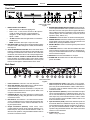 6
6
-
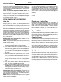 7
7
-
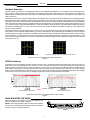 8
8
-
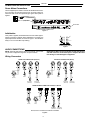 9
9
-
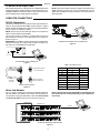 10
10
-
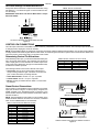 11
11
-
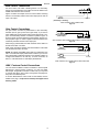 12
12
-
 13
13
-
 14
14
-
 15
15
-
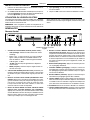 16
16
-
 17
17
-
 18
18
-
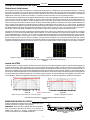 19
19
-
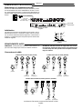 20
20
-
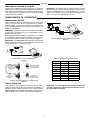 21
21
-
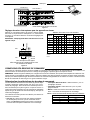 22
22
-
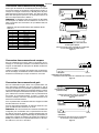 23
23
-
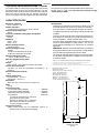 24
24
-
 25
25
-
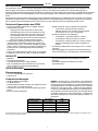 26
26
-
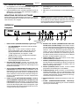 27
27
-
 28
28
-
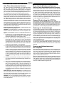 29
29
-
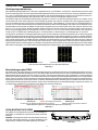 30
30
-
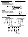 31
31
-
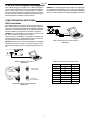 32
32
-
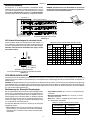 33
33
-
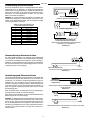 34
34
-
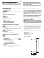 35
35
-
 36
36
-
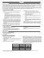 37
37
-
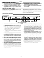 38
38
-
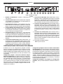 39
39
-
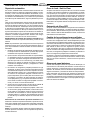 40
40
-
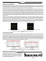 41
41
-
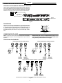 42
42
-
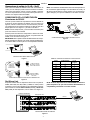 43
43
-
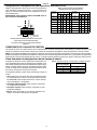 44
44
-
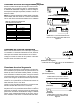 45
45
-
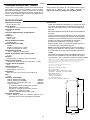 46
46
-
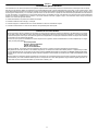 47
47
-
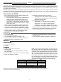 48
48
-
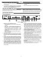 49
49
-
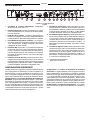 50
50
-
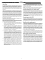 51
51
-
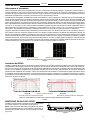 52
52
-
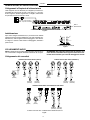 53
53
-
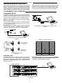 54
54
-
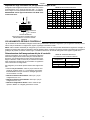 55
55
-
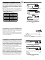 56
56
-
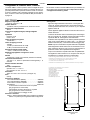 57
57
-
 58
58
-
 59
59
-
 60
60


Shure DFR22 Guida utente
- Categoria
- Apparecchiature musicali supplementari
- Tipo
- Guida utente
in altre lingue
- français: Shure DFR22 Mode d'emploi
- español: Shure DFR22 Guía del usuario
- Deutsch: Shure DFR22 Benutzerhandbuch
Documenti correlati
Altri documenti
-
DeLOCK 84626 Scheda dati
-
Yamaha EMX 5016CF Manuale utente
-
PROEL M-1000 Manuale utente
-
-
-
Peavey FX 2 16 Channel Non-Powered Mixer Manuale del proprietario
-
-
Behringer SX2442FX Guida Rapida
-
Yamaha MGP16X/MGP12X Manuale utente
-