
DOC026.98.80329
A1000, A1000XP
10/2015, Edition 2
Basic User Manual
Basis-Bedienungsanleitung
Manuale di base per l'utente
Manuel d'utilisation de base
Manual básico del usuario

English...................................................................................................................................................................................................3
Deutsch...............................................................................................................................................................................................29
Italiano................................................................................................................................................................................................. 57
Français.............................................................................................................................................................................................. 83
Español............................................................................................................................................................................................. 110
2

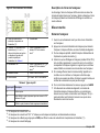
Table of contents
Specifications on page 3 Startup on page 22
General information on page 5 Operation on page 24
Installation on page 9 Maintenance on page 24
User interface and navigation
on page 20
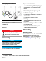
Additional information
Additional information is available on the manufacturer's website.
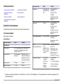
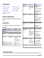
Specifications
Specifications are subject to change without notice.
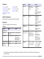
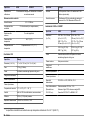
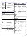
Performance
Specification A1000 A1000XP
TOC measurement
TOC method TOC = Total Carbon (TC) – Total Inorganic Carbon (TIC)
Linear range 0.05 to 1999 ppb as
carbon
XP mode: 0.02 to 1999 ppb as
carbon
1
Standard mode: 2.00 to
1999 ppb as carbon
Detection limit 0.05 ppb 0.02 ppb
Quantitation limit 0.17 ppb 0.07 ppb
Accuracy 0.5 ppb or ±5%
whichever is greater
±0.05 ppb (MDL to 0.999 ppb)
±0.1 ppb (1.000 to 1.999 ppb)
±0.5 ppb or 5% whichever is
greater (2 to 1999 ppb)
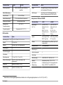
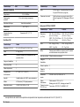
Specification A1000 A1000XP
Precision ±0.5 ppb ±0.05 ppb (MDL to 0.999 ppb)
±0.1 ppb (1.000 to 1.999 ppb)
±0.5 ppb or 5% whichever is
greater (2 to 1999 ppb)
TOC conductivity
range
0.2 to 18.2 MΩ-cm XP mode: 15.0 to 18.2 MΩ-cm
Standard mode: 0.2 to
18.2 MΩ-cm
TOC water
temperature range
0 to 100 °C (32 to
212 °F)
Note: Use a heat
exchanger for samples
more than 50 °C (122 °F).
XP mode: 18 to 32 °C (65 to
90 °F)
Standard mode: 0 to 100 °C
(32 to 212 °F)
Note: Use a heat exchanger for
samples more than 50 °C (122 °F).
Display resolution X.YY (0.00 to
19.99 ppb)
X.Y (20.0 to 199.9 ppb)
X (200 to 1999 ppb)
X.YYY (0.000 to 1.999 ppb)
X.YY (2.00 to 19.99 ppb)
X.Y (20.0 to 199.9 ppb)
X (200 to 1999 ppb)
Calibration stability Annual calibration or validation recommended
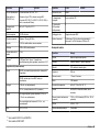
Resistivity measurement
Linear range 0.01 to 18 MΩ-cm
Resistivity accuracy
2
2% over full range (compensated)
Display resolution Three significant figures
Temperature
accuracy
±0.5 °C (9 °F)
Temperature
compensation
Compensated to 25 °C (77 °F)
1
The instrument changes to XP mode automatically when the TOC conductivity and temperature range are within the XP mode ranges shown.
2
Resistivity and accuracy specifications are for ambient temperatures from 15–35 °C (59–95 °F).
English 3

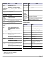
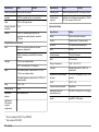
C80 controller
Specification Details
Dimensions (W x D x H) 8.1 x 4.8 x 12.0 cm (3.2 x 1.9 x 4.7 in.)
Weight 0.75 kg (1.5 lb)
Enclosure Aluminum, splash and drip resistant
Installation category II
Pollution degree 2
Protection class I
Operating temperature 5 °C to 40 °C (41 °F to 104 °F)
Humidity 0 to 90% relative humidity, non-condensing
Altitude 4000 meters (13,125 ft) maximum
Power requirements 120/230 VAC, 50/60 Hz, 7.6 W
Display 4 line x 16 character super twist LCD with 8 bi-color
(red/green) LEDs
Safety rating Certified to UL and CSA safety standards by CSA.
Marked with cCSAus and CE.
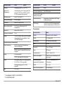
A1000 and A1000XP analyzers
Specification A1000 A1000XP
Dimensions
(W x D x L)
S10: 106 x 112 x 330 mm
(4.2 x 4.4 x 13.0 in.)
S20P: 172 x 112 x
330 mm (6.8 x 4.4 x
13.0 in.)
XP-S: 106 x 112 x 330 mm
(4.2 x 4.4 x 13.0 in.)
XP: 172 x 112 x 330 mm
(6.8 x 4.4 x 13.0 in.)
Weight S10: 6.5 kg (12.75 lb)
S20P: 7 kg (14 lb)
XP-S: 6.5 kg (12.75 lb)
XP: 7 kg (14 lb)
Specification A1000 A1000XP
Enclosure ABS front panel with Lexan
®
overlay, splash and drip
resistant
Enclosure rating Indoor use only.
Installation category II
Pollution degree 2
Protection class I
Power requirements 100-240 VAC ±10%, 50/60 Hz, 2/1 A
Power cord
(100–120 VAC main)
Rating: 125 VAC, 10 A
Foil shield 100%; braid shield 85%
Connectors: IEC 320–C13 and NEMA 5–15P
Power cord
(208–230 VAC main)
Rating: 250 VAC, 10 A
Foil shield 100%; braid shield 85%
Connectors: IEC 320–C13 and CEE 7/7 or CEI
23–16/VII (or like, depending on country)
Operating
temperature
5 to 35 °C (41 to 95 °F)
Sample flow rate 60–300 mL/minute
Sample pressure 100 psig (690 kPa) maximum
Humidity 0–95% relative humidity, non-condensing
Altitude 2000 m (6562 ft) maximum
Analysis cell volume 7.5 mL
Display
3
1 line x 16 character Super-Twist LCD with yellow
backlight (adjustable), 0.163 in. characters
3
A1000 S10 and A1000XP-S models only
4 English

Specification A1000 A1000XP
Inputs/Outputs (communications)
Serial RS232, three connectors (Data Acquisition, Printer
3
and
Diagnostics)
RS485, reserved for the local BNC cable for the
analyzer
Analog 4–20 mA, opto-isolated
12 VDC, non-isolated at 0.5 A (maximum)
Digital Two digital inputs, maximum input 5–30 VDC and
1–10 mA, opto-isolated
Two digital outputs that supply 5–30 VDC, opto-isolated
Bias 12 VDC, 0.5 A
Network protocol RS485
Maximum analyzers 8 per C80 controller
Maximum
C80 controllers (any
configuration)
8
Network cabling Shielded twin-axial, twist-lock BNC
Safety rating Certified to UL and CSA safety standards by CSA.
Marked with cCSAus and CE.
Thermal printer
Specification Details
Method Thermal, serial, dot-matrix
Format 9 dots high x 7 dots wide
Speed 52.5 characters per second (cps)
Width 89.6 mm
Specification Details
Paper size 112 mm, 40-column
Buffer 7400 characters
Temperature range 0 to 40 °C (32 to 104 °F)
Humidity 30 to 80% relative humidity, non-condensing
Power (via wall transformer) 120 VAC, 60 Hz standard (230 VAC, 50 Hz
optional)
NiCad
4
4.8 VDC, 1.5 A
Maximum power consumption Negligible
Dimensions (W x D x H) 160 x 66.5 x 170 mm (6.3 x 2.6 x 6.7 in.)
Interface RS232 serial, 1200 baud
General information
In no event will the manufacturer be liable for direct, indirect, special,
incidental or consequential damages resulting from any defect or
omission in this manual. The manufacturer reserves the right to make
changes in this manual and the products it describes at any time, without
notice or obligation. Revised editions are found on the manufacturer’s
website.
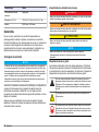
Safety information
N O T I C E
The manufacturer is not responsible for any damages due to misapplication or
misuse of this product including, without limitation, direct, incidental and
consequential damages, and disclaims such damages to the full extent permitted
under applicable law. The user is solely responsible to identify critical application
risks and install appropriate mechanisms to protect processes during a possible
equipment malfunction.
Please read this entire manual before unpacking, setting up or operating
this equipment. Pay attention to all danger and caution statements.
4
A1000 S20P model only
English 5

Failure to do so could result in serious injury to the operator or damage
to the equipment.
Make sure that the protection provided by this equipment is not impaired.
Do not use or install this equipment in any manner other than that
specified in this manual.
Use of hazard information
D A N G E R
Indicates a potentially or imminently hazardous situation which, if not avoided, will
result in death or serious injury.
W A R N I N G
Indicates a potentially or imminently hazardous situation which, if not avoided,
could result in death or serious injury.
C A U T I O N
Indicates a potentially hazardous situation that may result in minor or moderate
injury.
N O T I C E
Indicates a situation which, if not avoided, may cause damage to the instrument.
Information that requires special emphasis.
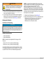
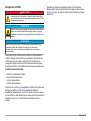
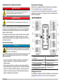
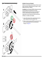
Precautionary labels
Read all labels and tags attached to the instrument. Personal injury or
damage to the instrument could occur if not observed. A symbol on the
instrument is referenced in the manual with a precautionary statement.
This is the safety alert symbol. Obey all safety messages that follow
this symbol to avoid potential injury. If on the instrument, refer to the
instruction manual for operation or safety information.
This symbol indicates that a risk of electrical shock and/or
electrocution exists.
This symbol indicates that the marked item requires a protective earth
connection. If the instrument is not supplied with a ground plug on a
cord, make the protective earth connection to the protective
conductor terminal.
This symbol indicates the presence of devices sensitive to Electro-
static Discharge (ESD) and indicates that care must be taken to
prevent damage with the equipment.
Electrical equipment marked with this symbol may not be disposed of
in European public disposal systems after 12 August of 2005. In
conformity with European local and national regulations (EU Directive
2002/96/EC), European electrical equipment users must now return
old or end-of-life equipment to the Producer for disposal at no charge
to the user.
Note: For return for recycling, please contact the equipment producer or supplier
for instructions on how to return end-of-life equipment, producer-supplied
electrical accessories, and all auxiliary items for proper disposal.
Certification
Canadian Radio Interference-Causing Equipment Regulation,
IECS-003, Class A:
Supporting test records reside with the manufacturer.
This Class A digital apparatus meets all requirements of the Canadian
Interference-Causing Equipment Regulations.
Cet appareil numérique de classe A répond à toutes les exigences de la
réglementation canadienne sur les équipements provoquant des
interférences.
FCC Part 15, Class "A" Limits
Supporting test records reside with the manufacturer. The device
complies with Part 15 of the FCC Rules. Operation is subject to the
following conditions:
1. The equipment may not cause harmful interference.
2. The equipment must accept any interference received, including
interference that may cause undesired operation.
Changes or modifications to this equipment not expressly approved by
the party responsible for compliance could void the user's authority to
6
English

operate the equipment. This equipment has been tested and found to
comply with the limits for a Class A digital device, pursuant to Part 15 of
the FCC rules. These limits are designed to provide reasonable
protection against harmful interference when the equipment is operated
in a commercial environment. This equipment generates, uses and can
radiate radio frequency energy and, if not installed and used in
accordance with the instruction manual, may cause harmful interference
to radio communications. Operation of this equipment in a residential
area is likely to cause harmful interference, in which case the user will be
required to correct the interference at their expense. The following
techniques can be used to reduce interference problems:
1. Disconnect the equipment from its power source to verify that it is or
is not the source of the interference.
2. If the equipment is connected to the same outlet as the device
experiencing interference, connect the equipment to a different
outlet.
3. Move the equipment away from the device receiving the interference.
4. Reposition the receiving antenna for the device receiving the
interference.
5. Try combinations of the above.
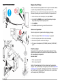
Product overview
D A N G E R
Chemical or biological hazards. If this instrument is used to monitor a
treatment process and/or chemical feed system for which there are
regulatory limits and monitoring requirements related to public health,
public safety, food or beverage manufacture or processing, it is the
responsibility of the user of this instrument to know and abide by any
applicable regulation and to have sufficient and appropriate
mechanisms in place for compliance with applicable regulations in the
event of malfunction of the instrument.
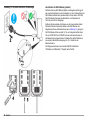
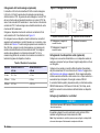
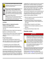
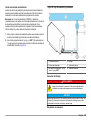
The A1000 and A1000XP TOC analyzers use UV light to oxidize water
samples for TOC analysis in pure and ultra-pure water for the semi-
conductor industry. Refer to Figure 1 and Figure 2. No reagents or gases
are used in the process. The conductivity of each sample (in ppb) is
measured two times, once before and once after sample oxidation by
ultraviolet (UV) light.
An integral alarm scheme reports any abnormalities found during the
analyzer operation. A TOC limit excursion is automatically sent to a
printer and shown on the display of the connected C80 controller.
The analyzers are used with the C80 controller for data collection and
operation. Refer to Figure 3 and User interface on page 20. More
analyzers and C80 controllers can be connected to make a local area
network. Multiple analyzers can be connected to one C80 controller to
monitor several process points from one location. As an alternative,
multiple controllers can be connected to show analyzer readings at many
locations.
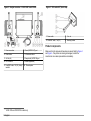
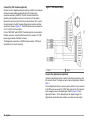
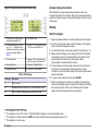
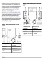
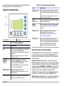
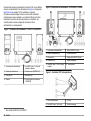
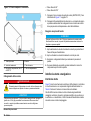
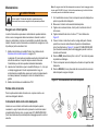
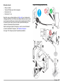
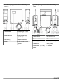
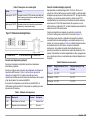
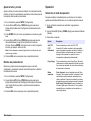
Figure 1 Analyzer overview – A1000 S10 and A1000XP-S
1 Power connection 5 Local BNC cable, 1 M (3 ft), factory
installed
2 Power button 6 Drain (WATER OUT) port
3 Air filter (2x) 7 I/O connector block
4 Display 8 Sample inlet (WATER IN) port
English 7

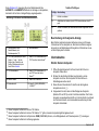
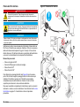
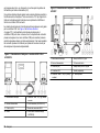
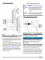
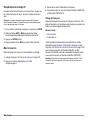
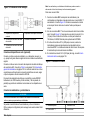
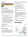
Figure 2 Analyzer overview – A1000 S20P and A1000XP
1 Power connection 6 Drain (WATER OUT) port
2 Power button 7 I/O connector block
3 Air filter (2x) 8 Sample inlet (WATER IN) port
4 C80 Controller 9 Handle (adjustable)
5 Local BNC cable, 1 M (3 ft), factory
installed
10 Thermal printer
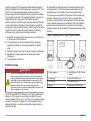
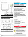
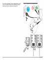
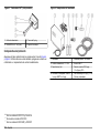
Figure 3 C80 controller
5
(back view)
1 Power cable 3 ¾-in. nut
2 Local BNC cable, 1 m (3 ft) 4 Mounting bracket
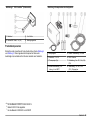
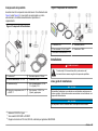
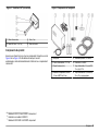
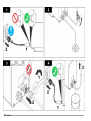
Product components
Make sure that all components have been received. Refer to Figure 4
and Figure 5. If any items are missing or damaged, contact the
manufacturer or a sales representative immediately.
5
A1000 S10 and A1000XP-S models only
8 English

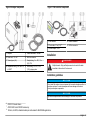
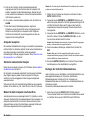
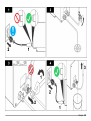
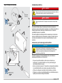
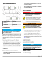
Figure 4 Analyzer components
1 Analyzer
6
5 Passive terminator, 120-ohm
2 Power cord, 115 VAC 6 BNC tee connector
3 Thermal paper (2x)
7
7 Sample tubing, ¼ in. OD, 1.7 m
(5 ft), PFA
4 Compression fitting, ¼-in. tube x ¼-
in. MNPT
8 Drain tubing, ¼ in. OD, 3.3 m
(10 ft), polypropylene
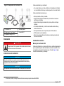
Figure 5 C80 controller components
1 C80 controller 4 Passive terminator
2 Trunk cable, 3.3 m (10 ft)
8
5 BNC tee connector
3 Power adapter, 9 VDC
Installation
D A N G E R
Multiple hazards. Only qualified personnel must conduct the tasks
described in this section of the document.
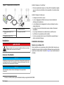
Installation guidelines
N O T I C E
Do not install the analyzer in an environment with a caustic atmosphere without a
protective enclosure. A caustic atmosphere will cause damage to electronic
circuitry and analyzer components.
N O T I C E
High internal temperatures will cause damage to instrument components.
6
A1000 S10 model shown
7
A1000 S20P and A1000XP models only
8
120-ohm, 24 AWG, shielded twisted pair cable made for EIA RS485 applications.
English 9

Install the analyzer and controller:
• In a clean, dry, well ventilated, temperature controlled location with
minimum vibration that does not receive direct exposure to sunlight.
Install the analyzer so that:
• It is upright and level.
• There is sufficient clearance around it to make plumbing and electrical
connections.
• There is sufficient clearance around it to remove the two end covers.
• The power cord and power button are visible and easily accessible.
• There is no air flow restriction through the air filters.
• The air filters do not get wet.
• It is as near the sample source as possible to decrease analysis
delay.
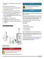
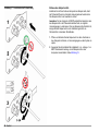
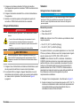
Mechanical installation
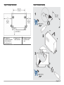
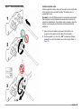
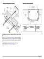
C80 controller mounting
Install the controller in a flat, stable, vertical panel. Make sure that the
top surface of the controller is level. Cut an opening in the panel at eye
level. Refer to Figure 6 for dimensions and mounting.
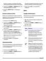
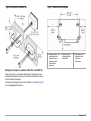
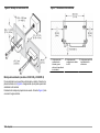
Figure 6 C80 controller mounting
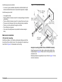
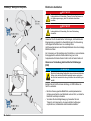
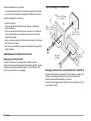
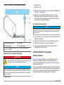
Analyzer mounting (A1000 S10 and A1000XP-S models)
Attach the analyzer to a flat, stable, vertical surface. Refer to the
illustrated steps in Figure 8. Make sure that the top surface of the
analyzer is level.
Mounting hardware is supplied by the user. Refer to Figure 7 for the
minimum clearances.
10
English

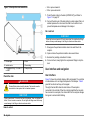
Figure 7 Analyzer dimensions
1 Clearance for
plumbing connections
and to remove the
plumbing end cover
2 Clearance for I/O
cable connections
3 Clearance to remove
the electronic end
cover
Figure 8 Analyzer mounting
English 11

Electrical installation
D A N G E R
Electrocution hazard. Always remove power to the instrument before
making electrical connections.
D A N G E R
Electrocution hazard. Protective Earth Ground (PE) connection is
required.
Use shielded twisted-pair cable for all electrical connections except input
power. Use of non-shielded cable may result in radio frequency emission
or susceptibility levels higher than the allowed levels.
To prevent shock hazards from ground currents in inadequate ground
systems, connect the shield at only the analyzer end. Do not connect the
shield wire at both ends.
Electrostatic discharge (ESD) considerations
N O T I C E
Potential Instrument Damage. Delicate internal electronic components
can be damaged by static electricity, resulting in degraded
performance or eventual failure.
Refer to the steps in this procedure to prevent ESD damage to the
instrument:
• Touch an earth-grounded metal surface such as the chassis of an
instrument, a metal conduit or pipe to discharge static electricity from
the body.
• Avoid excessive movement. Transport static-sensitive components in
anti-static containers or packages.
• Wear a wrist strap connected by a wire to earth ground.
• Work in a static-safe area with anti-static floor pads and work bench
pads.
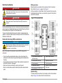
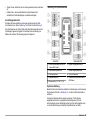
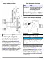
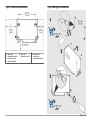
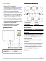
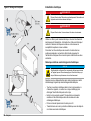
Wiring overview
Make all electrical connections to the analyzer at the I/O connector
block. Refer to Figure 1 on page 7 and Figure 9.
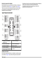
All the connectors on the left side of the I/O connector block are opto-
isolated connectors and have no connection to ground or the internal
power of the analyzer.
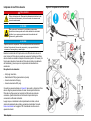
Figure 9 I/O connector block
1 A-Net network connector (local
BNC cable only)
6 Digital Outputs connector
2 Data Acquisition connector 7 Digital Inputs connector
3 Printer connector 8 4–20 mA connector
4 Diagnostics connector 9 Auxillary connector (optional local
BNC cable)
5 Bias connector (12 VDC, 0.5 A)
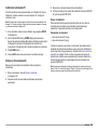
System wiring
To make electrical connections to the analyzer, refer to the illustrated
steps in Figure 10 to remove the I/O connector block.
12
English

To install the I/O connector block, do the illustrated steps in the reverse
order. The I/O connector block must be fully assembled and installed to
keep the RF emissions specifications.
Figure 10 Make electrical connections
English 13

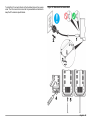
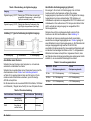
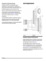
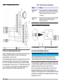
Connect the DAC modules (optional)
Connect two DAC (digital-to-analog conversion) modules to the analyzer
with the two serial cables supplied with the DAC modules (four-
conductor serial cable, AWG 28). The DAC modules transmit the
resistivity and temperature values as 0–20 mA or 4–20 mA outputs.
Remove the serial connectors from the two serial cables. Then, connect
the serial cables to the DAC modules, Diagnostics connector and Bias
connector as shown in Figure 11. The DAC modules can be a maximum
of 16.7 m (50 ft) from the analyzer.
For the A1000 S20P and A1000XP, the attached printer is connected to
the Bias connector. Connect the DAC modules to an external +12 VDC
power supply instead of the Bias connector.
The Diagnostics connector is an RS232C series interface, 1200 baud
and 8 data bits (1 stop bit, no parity).
Figure 11 DAC module wiring
1 DAC 1 2 DAC 2
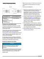
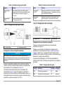
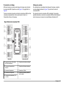
Connect the digital inputs (optional)
Connect a remote device and/or a switch to the Inputs connector on the
I/O connector block. The Inputs connector has two digital inputs. Refer to
Table 1.
The two digital inputs share a common positive terminal. Use an external
5–30 VDC power source or the 12 VDC bias output on the I/O connector
block to supply power to the digital inputs. Refer to Figure 12. Each
digital input draws 1–14 mA, depending on the applied voltage. The
digital inputs operate from open collector, open drain or relay outputs.
14
English

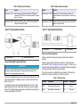
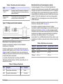
Table 1 Digital input description
Input Function
Digital Input 1 (IN1) Starts an analysis (high-to-low state) when Digital Input
2 selects Auto TOC mode. The minimum period for a signal
pulse is 0.1 second.
Digital Input 2 (IN2) Selects the operating mode—Auto TOC mode (high state)
or Purge Only mode (low state).
Figure 12 Typical digital input wiring
1 Bias connector 2 External power source
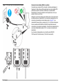
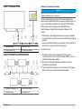
Connect the digital outputs (optional)
N O T I C E
Do not use the digital outputs for process control functions such as pump on/off
switching or water system shutdown. The digital output connections do not
replace a PLC (programmable logic controller).
Connect a compatible device such as a remote alarm indicator or PLC to
the Outputs connector and Bias connector on the I/O connector block.
Refer to Figure 13.
The Outputs connector has two digital outputs. Refer to Table 2. Both
digital outputs are 8.5 mA current sinks that share a common negative
terminal. The digital outputs supply power to solid state relay inputs and
have an input range of 5–30 VDC.
Table 2 Digital output description
Output Function
Digital Output 1 (OUT1) Transmits the TOC value as above or below the
selected alarm limit—below (high state) or above (low
state).
Digital Output 2 (OUT2) Transmits the status of the sample valve—open (high
state) or closed (low state).
Figure 13 Typical digital output wiring
1 Relay inputs 2 Solid state relay 3 Relay outputs
Connect a printer (optional)
Connect a printer to the analyzer to get automatic and on-demand
printouts.
Connect a serial cable to the Printer connector on the I/O connector
block. Refer to Table 3 and Wiring overview on page 12. A three- or five-
conductor serial cable is sufficient for most serial interfaces, depending
on the type of printer. AWG 24 is recommended.
The Printer connector is an RS232C series interface, 1200 baud and
8 data bits (1 stop bit, no parity), for a 40-column printer.
Table 3 Printer wiring
Terminal Description Terminal Description
TxD2 Data (white with blue stripe) SG Ground
RxD2 Busy (blue with white stripe) PG Not used
English 15

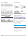
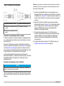
Connect the analog output (optional)
One 0–20 mA or 4–20 mA analog output is available at the 4–20 mA
connector on the I/O connector block. The analog output signal is
proportional to the last TOC reading. The analog output range and its
corresponding TOC zero-scale and full-scale values are the same as the
selected DAC TOC zero-scale and full-scale values. If a critical error
occurs during a TOC analysis, the analog output goes to the selected
DAC error output state.
Connect a current receiving device to the 4–20 mA connector on the I/O
connector block. Refer to Figure 14.
To connect a voltage receiving device instead, convert the analog output
signal to a voltage output with a resistor as shown in Table 4. The
analog output drives resistance between 50 and 500 ohms, including the
interconnecting cables. The precision of the resistor directly affects the
accuracy of the data. A 1% wire-wound resistor or better is
recommended. For maximum data integrity, make sure that the resistor
is installed across the input terminals of the receiving device.
Table 4 Conversion resistors
Resistor 4–20 mA DC voltage range 0–20 mA DC voltage range
50 ohms 0.2–1 VDC 0–1 VDC
250 ohms 1–5 VDC 0–5 VDC
500 ohms 2–10 VDC 0–10 VDC
Figure 14 Analog output wiring
1 Current receiving device 4 Voltage receiving device
2 Wiring for a current output signal 5 Conversion resistor
3 Wiring for a voltage output signal
Connect a serial device (optional)
Connect a serial cable to the analyzer and to a serial device (e.g., host
computer) to get the alarm log or all log entries.
Connect the serial cable to the Data Acquisition connector on the I/O
connector block. Refer to Table 3 on page 15 and Wiring overview
on page 12. A three- or five-conductor serial cable is sufficient for most
serial interfaces, depending on the type of printer. AWG 24 is
recommended.
The Data Acquisition connector is a bidirectional RS232C series
interface, 1200 baud and 8 data bits (1 stop bit, no parity), that lets the
analyzer communicate with serial devices.
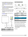
Connect the analyzers and controllers
N O T I C E
Do not use standard BNC terminators. Only use passive or active terminators
supplied by the manufacturer.
As many as eight analyzers and eight C80 controllers can be connected
in any configuration to make a number of different A-Net networks.
Note: Individual analyzers and controllers can be connected or disconnected from
the network without disrupting overall network operation.
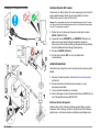
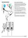
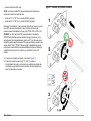
To make an A-Net network:
16
English

1. Connect the local BNC cables for the analyzers and any non-
integrated controllers(s) to the middle coupling of a supplied BNC tee
connector. Refer to Figure 15. Gently push the cable onto the
coupling. Twist the cable onto the connector until it locks on the
coupling.
2. Connect the BNC tee connectors with sections of twin-axial trunk
cable. Refer to Figure 16. A 3.3 m (10 ft) trunk cable is supplied. Use
a 120-ohm, AWG 24, shielded twisted pair cable made for EIA
RS485 applications for the trunk cable.
3. If the trunk line is 167 m (500 ft) in length or less, connect a supplied
passive terminator to the open coupling of the BNC tee connectors at
both ends of the trunk cable. Termination is necessary for reliable
communications.
4. If the trunk line is more than 167 m (500 ft) in length, refer to Use
active termination on page 17.
Figure 15 Cable connections
1 Passive terminator 3 Local BNC cable
2 BNC tee connector 4 Trunk cable
Figure 16 A-Net communication connections
1 AC-powered terminator 3 Trunk cable
2 Passive terminator 4 Local BNC cable
Use active termination
N O T I C E
Do not use standard BNC terminators. Only use passive or active terminators
supplied by the manufacturer.
The A-Net network must be configured as one trunk cable with local
BNC cables no longer than 1 m (3 ft) in length. The trunk cable can be a
maximum of 1000 m (3000 ft), not including local BNC cable lengths.
When the trunk cable length will be more than 167 m (500 ft):
• Install the trunk cable in conduit that does not contain any other
cables or AC buses to prevent potential electrical interference.
• Use active (AC-powered) termination to control noise and supply a
clean communication signal.
Active termination:
English
17

1. Connect an AC-powered terminator supplied by the manufacturer to
the open coupling of the BNC tee connector at one end of the trunk
cable.
2. Connect the AC-powered terminator to an applicable AC power
source.
3. Install a passive terminator on the open coupling of the BNC tee
connector at the other end of the trunk cable.
Connect to power
D A N G E R
Electrical shock and fire hazards. Replacement power cords must:
• Have the correct plug style for the outlet connection
• Have a rating sufficient for the supply voltage and current. Refer to
the requirements in the Specifications section.
• Meet or exceed local electrical code requirements
W A R N I N G
Electrocution hazard. Only the hot (L) connection is fused. Connect
only single phase power sources to equipment. Do not use bi-phase or
poly-phase supply sources.
1. Connect the supplied power cord to the analyzer, then to a mains
electrical outlet with protective earth ground.
2. For non-integrated C80 controllers, connect the power adapter to the
controller power cable, then a mains electrical outlet with protective
earth ground. Refer to Figure 5 on page 9.
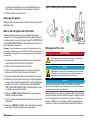
Plumbing
Plumb the sample line
N O T I C E
Tighten a new ferrule 1¼ turns the first time it is tightened. Then, only tighten the
ferrule 1/8 turn to make a connection. Do not tighten the fittings more as this may
cause damage to the fittings or ferrules and cause leaks.
Items to collect:
• 3/4-in. open-end wrench
• 9/16-in. open-end wrench
A1000—Do not use the supplied PFA tubing for installations when the
sample is:
• More than 75 °C (167 °F) and more than 620 kPa (90 psig)
• More than 85 °C (185 °F) and more than 550 kPa (80 psig)
For these installations, or for any application where the use of PFA
tubing is a concern, use high-grade ¼-in. (OD) PTFE, FEP, PVDF or
316 stainless steel sample tubing instead.
A1000XP—Do not use the supplied PFA tubing. The A1000XP analyzer
is designed for the purest water systems so use non-permeable tubing,
such as Kynar
®
or 316L electro-polished stainless steel for the sample
tubing. Teflon
™
PFA/PTFE can be used, but there is a potential for
sample corruption due to the permeability of the tubing. Keep the
distance between the sample point and the analyzer as short as
possible.
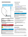
1. Plumb the sample tubing. Refer to Figure 17.
2. When the sample is more than 50 °C (122 °F), install a heat
exchanger in the sample line upstream of the analyzer or erratic
readings will occur. The heat exchanger is supplied by the user.
18 English

Figure 17 Plumb the sample tubing
Install an isolation valve
Install an upstream isolation valve near the analyzer so the sample flow
to the analyzer can be controlled manually. The isolation valve is
supplied by the user.
Exception: For the A1000XP analyzer, the manufacturer recommends
that no isolation valve be installed in the sample line to minimize the
potential for contamination. If an isolation valve is necessary, clean the
isolation valve thoroughly of all lubrication and other debris before
installation.
1. Open and close the isolation valve several times before it is
connected to the analyzer to flush debris from the system.
2. Use the supplied ¼-in. tube x ¼-in. MNPT compression fitting as
necessary to connect the isolation valve to the analyzer. Refer to
Figure 18.
English 19

Figure 18 Sample flow and connections
1 Process pipe 4 Drain
2 Isolation valve 5 Drain tubing
3 Compression fitting, ¼-in. tube x ¼-
in. MNPT
6 Sample tubing
Plumb the drain
D A N G E R
Potential Electrical shock and fire hazards. The drain line must be
connected to a drain system that is at ambient pressure.
N O T I C E
Tighten a new ferrule 1¼ turns the first time it is tightened. Then, only tighten the
ferrule 1/8 turn to make a connection. Do not tighten the fittings more as this may
cause damage to the fittings or ferrules and cause leaks.
Items to collect:
• 3/4-in. open-end wrench
• 9/16-in. open-end wrench
1. Plumb the drain tubing to the drain (WATER OUT) port. Refer to
Figure 17 on page 19.
2. Connect the other end of the drain tubing to a drain system that is at
ambient pressure. Do not connect the drain line to another line to
prevent backpressure and damage to the analyzer.
Do a leak test
N O T I C E
Tighten the ferrule only another 1/8 turn to stop a leak. Do not tighten the fittings
more as this may cause damage to the fittings or ferrules and cause leaks.
1. Slowly open the upstream isolation valve to let water flow to the
analyzer.
2. Open and close the upstream isolation valve several times.
3. Examine the plumbing connections for leaks.
4. If a leak is found, slowly tighten the compression fittings to stop the
leak.
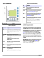
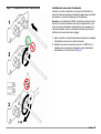
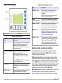
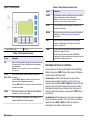
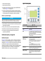
User interface and navigation
User interface
Figure 19 shows the controller display, LEDs and keypad. The controller
is a stand-alone unit or an integral component of the analyzer. Table 5
gives the function of each key on the keypad.
The eight channel LEDs show the alarm status of the analyzers
connected to the controller. When the controller identifies that an alarm
has occurred on an analyzer, the channel LED for the analyzer changes
from green to red and starts flashing.
20
English
La pagina si sta caricando...
La pagina si sta caricando...
La pagina si sta caricando...
La pagina si sta caricando...
La pagina si sta caricando...
La pagina si sta caricando...
La pagina si sta caricando...
La pagina si sta caricando...
La pagina si sta caricando...
La pagina si sta caricando...
La pagina si sta caricando...
La pagina si sta caricando...
La pagina si sta caricando...
La pagina si sta caricando...
La pagina si sta caricando...
La pagina si sta caricando...
La pagina si sta caricando...
La pagina si sta caricando...
La pagina si sta caricando...
La pagina si sta caricando...
La pagina si sta caricando...
La pagina si sta caricando...
La pagina si sta caricando...
La pagina si sta caricando...
La pagina si sta caricando...
La pagina si sta caricando...
La pagina si sta caricando...
La pagina si sta caricando...
La pagina si sta caricando...
La pagina si sta caricando...
La pagina si sta caricando...
La pagina si sta caricando...
La pagina si sta caricando...
La pagina si sta caricando...
La pagina si sta caricando...
La pagina si sta caricando...
La pagina si sta caricando...
La pagina si sta caricando...
La pagina si sta caricando...
La pagina si sta caricando...
La pagina si sta caricando...
La pagina si sta caricando...
La pagina si sta caricando...
La pagina si sta caricando...
La pagina si sta caricando...
La pagina si sta caricando...
La pagina si sta caricando...
La pagina si sta caricando...
La pagina si sta caricando...
La pagina si sta caricando...
La pagina si sta caricando...
La pagina si sta caricando...
La pagina si sta caricando...
La pagina si sta caricando...
La pagina si sta caricando...
La pagina si sta caricando...
La pagina si sta caricando...
La pagina si sta caricando...
La pagina si sta caricando...
La pagina si sta caricando...
La pagina si sta caricando...
La pagina si sta caricando...
La pagina si sta caricando...
La pagina si sta caricando...
La pagina si sta caricando...
La pagina si sta caricando...
La pagina si sta caricando...
La pagina si sta caricando...
La pagina si sta caricando...
La pagina si sta caricando...
La pagina si sta caricando...
La pagina si sta caricando...
La pagina si sta caricando...
La pagina si sta caricando...
La pagina si sta caricando...
La pagina si sta caricando...
La pagina si sta caricando...
La pagina si sta caricando...
La pagina si sta caricando...
La pagina si sta caricando...
La pagina si sta caricando...
La pagina si sta caricando...
La pagina si sta caricando...
La pagina si sta caricando...
La pagina si sta caricando...
La pagina si sta caricando...
La pagina si sta caricando...
La pagina si sta caricando...
La pagina si sta caricando...
La pagina si sta caricando...
La pagina si sta caricando...
La pagina si sta caricando...
La pagina si sta caricando...
La pagina si sta caricando...
La pagina si sta caricando...
La pagina si sta caricando...
La pagina si sta caricando...
La pagina si sta caricando...
La pagina si sta caricando...
La pagina si sta caricando...
La pagina si sta caricando...
La pagina si sta caricando...
La pagina si sta caricando...
La pagina si sta caricando...
La pagina si sta caricando...
La pagina si sta caricando...
La pagina si sta caricando...
La pagina si sta caricando...
La pagina si sta caricando...
La pagina si sta caricando...
La pagina si sta caricando...
La pagina si sta caricando...
La pagina si sta caricando...
La pagina si sta caricando...
La pagina si sta caricando...
La pagina si sta caricando...
La pagina si sta caricando...
La pagina si sta caricando...
-
 1
1
-
 2
2
-
 3
3
-
 4
4
-
 5
5
-
 6
6
-
 7
7
-
 8
8
-
 9
9
-
 10
10
-
 11
11
-
 12
12
-
 13
13
-
 14
14
-
 15
15
-
 16
16
-
 17
17
-
 18
18
-
 19
19
-
 20
20
-
 21
21
-
 22
22
-
 23
23
-
 24
24
-
 25
25
-
 26
26
-
 27
27
-
 28
28
-
 29
29
-
 30
30
-
 31
31
-
 32
32
-
 33
33
-
 34
34
-
 35
35
-
 36
36
-
 37
37
-
 38
38
-
 39
39
-
 40
40
-
 41
41
-
 42
42
-
 43
43
-
 44
44
-
 45
45
-
 46
46
-
 47
47
-
 48
48
-
 49
49
-
 50
50
-
 51
51
-
 52
52
-
 53
53
-
 54
54
-
 55
55
-
 56
56
-
 57
57
-
 58
58
-
 59
59
-
 60
60
-
 61
61
-
 62
62
-
 63
63
-
 64
64
-
 65
65
-
 66
66
-
 67
67
-
 68
68
-
 69
69
-
 70
70
-
 71
71
-
 72
72
-
 73
73
-
 74
74
-
 75
75
-
 76
76
-
 77
77
-
 78
78
-
 79
79
-
 80
80
-
 81
81
-
 82
82
-
 83
83
-
 84
84
-
 85
85
-
 86
86
-
 87
87
-
 88
88
-
 89
89
-
 90
90
-
 91
91
-
 92
92
-
 93
93
-
 94
94
-
 95
95
-
 96
96
-
 97
97
-
 98
98
-
 99
99
-
 100
100
-
 101
101
-
 102
102
-
 103
103
-
 104
104
-
 105
105
-
 106
106
-
 107
107
-
 108
108
-
 109
109
-
 110
110
-
 111
111
-
 112
112
-
 113
113
-
 114
114
-
 115
115
-
 116
116
-
 117
117
-
 118
118
-
 119
119
-
 120
120
-
 121
121
-
 122
122
-
 123
123
-
 124
124
-
 125
125
-
 126
126
-
 127
127
-
 128
128
-
 129
129
-
 130
130
-
 131
131
-
 132
132
-
 133
133
-
 134
134
-
 135
135
-
 136
136
-
 137
137
-
 138
138


Hach A1000XP Basic User Manual
- Tipo
- Basic User Manual
- Questo manuale è adatto anche per
in altre lingue
- English: Hach A1000XP
- français: Hach A1000XP
- español: Hach A1000XP
- Deutsch: Hach A1000XP
Documenti correlati
-
 Hach Polymetron 9610sc SiO2 Guida d'installazione
-
 Hach Lange astroTOC Basic User Manual
-
Hach SC200 Basic User Manual
-
 Hach Polymetron 9526 Basic User Manual
-
Hach CL17sc Manuale utente
-
 Hach ORBISPHERE 510 Basic User Manual
-
 Hach Lange ORBISPHERE 3100 Basic User Manual
-
 Hach Lange ORBISPHERE 3100 Basic User Manual
-
 Hach 9586sc Basic User Manual
-
 Hach Polymetron 9523sc pH Basic User Manual


Altri documenti
-
Xqisit XQ S10 Quick Manual
-
Flint Garden FGC2267110VFG Istruzioni per l'uso
-
Mettler Toledo 5000TOCi Sensor Istruzioni per l'uso
-
 Teledyne 317R Manuale utente
-
Rosemount X-STREAM Enhanced XECLD Continuous Gas Analyzer Manuale del proprietario
-
Extech Instruments MO270 Manuale utente
-
wtw TetraCon 325 Instruction manuals
-
Husqvarna 40-C80 Charging Rail Manuale utente
