Genius TRIGON External Remote Release Istruzioni per l'uso
- Tipo
- Istruzioni per l'uso

E
F
G
H
C
A
B
==
H
L
O
M
Y
NB. KIT DA MONTARE ASSIEME AL CONTENITORE DI SICUREZZA COD. P508
ISTRUZIONI MONTAGGIO KIT
Il “kit sblocco esterno per cancello ad ante e portone a libro” permette di sbloccare il
motoriduttore quando questo è installato ad altezze non raggiungibili dall’utente. Per il montaggio
seguire attentamente le istruzioni:
1) Nota bene: la mancanza del “kit gruppo finecorsa” potrebbero non garantire la funzionalità
dello sblocco.
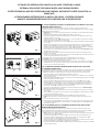
2) Fissare la squadretta A al moriduttore B tramite le viti C, come in Fig. 1.
3) Togliere il seeger E ed estrarre il perno F. Reinserire in perno F nel foro G del motoriduttore e
calzare il disco H, come in Fig.1.
4) Orientare il punto L con le viti M e stringere il grano con la chiave O, mantenendo il canalino
del disco H in asse con il registro Y, come in Fig.2.
5) Inserire nella parte posteriore del contenitore Q il particolare plastico D per la guida dei perni,
come in Fig.3.
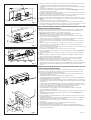
6) Eseguire un foro sulla parete a 130 cm. dal pavimento di diametro min. 8. Prima di fissare o mu-
rare il contenitore Q alla parete, infilare la guaina U nel foro praticato nella parete (Fig. 4).
7) Inserire il cavo T prima nel pomello X, poi nelcontenitore Q e poi nella guaina U, come in Fig.4.
8) Posizionare il contenitore Q in battuta sul muro o nello scasso predisposto.
9) Far scorrere tutto il cavo T nella guaina U; inserire poi in cavo T nel foro senza registro V della
squadretta A, come in Fig.5.
10) Inserire il cavo T nel canalino del disco H, arrotorarlo intorno ad esso e farlo passare sotto il
piattino Z, come in Fig.6.
11) Inserire il cavo T nel registro Y, calzare su di esso prima la molla W, poi il morsetto K. Tensionare il
cavo T e stringere il morsetto K, come in Fig.7.
12) Bloccare poi il cavo T sul disco H avvitando le viti M, orientato come in Fig.7.
13) Regolare la buona funzionalità dello sblocco tramite il registro Y, come in Fig.8.
14) Montare la serratura S sullo sportello I,come in Fig.8.
15) Inserire nello sportello I le molle e i perni R in sede, come in fig. 8. Tenere premuto con le dita i
perni R all’interno del coperchio I. Far scivolare il coperchio all’interno del contenitore Q sino
a scatto avvenuto dei perni in posizione.
N.B.: KIT MUST BE INSTALLED TOGETHER WITH SECURITY BOX CODE P508
KIT ASSEMBLY INSTRUCTIONS
The “external release kit for swing gates and folding doors” allows the gearbox to be released when
this is installed at a height inaccessible to the user. For assembly follow the instructions carefully:
1) Note: the absence of the limit switch kit could affect functionality of the release device.
2) Mount bracket A on gear motor B using screws C as shown in Fig. 1.
3) Take off circlip E and remove pin F. Fit pin F back in the gear motor hole G and mount disc H on
the pin as shown in Fig.1.
4) Orient point L with screws M and tighten the dowel with wrench O, keeping the groove of disk H
in line with adjuster Y, as shown in fig. 2.
5) Insert the plastic item D to guide the pins into the rear of the container Q as shown in Fig.3.
6) Drill a hole, with a min. diameter of 8, on the wall, 130 cm from the floor. Before attaching the
container Q to the wall or walling in, insert the sheath U in the hole drilled in the wall (Fig.4).
7) Insert cable T firstly in the knob X, then in the container Q and finally in sheath U, as per Fig. 4.
8) Position the container Q up against the wall or in the recess.
9) Thread the entire cable T into the sheath U. Then insert cable T into the hole without adjuster
screw V on bracket A as shown in Fig.5.
10) Insert cable T into its seat on disc H, wind it around the disc and thread it under the cover Z as
shown in Fig.6.
11) Insert cable T into the adjuster screw Y and fit onto it first spring W then clamp K. Tension cable T
and tighten clamp K as shown in Fig.7.
12) Fasten cable T onto disc H by tightening the screws M, oriented as shown in Fig.7.
13) Adjust the release device so that it is perfectly functional using adjuster screw Y as shown in
Fig.8.
14) Mount the lock S on the door I, as shown in Fig.8.
15) Insert the springs and the pins R in the seat in the door I, as shown in fig. 8. Use the fingers to conti-
nue pressing the pins R inside the cover I. Make the cover slide inside the container Q until the
pins snap into position.
N.B.: KIT À MONTER AVEC LE COFFRET DE SÉCURITÉ CODE ARTICLE P508
INSTRUCTIONS DE MONTAGE DU KIT
Le “kit de déverrouillage de l’extérieur pour portails battants et portes pliantes à la française”
permet de débloquer le motoréducteur lors que ce dernier est situé à une hauteur inaccessible
pour l’usager. Pour le montage du kit, suivre attentivement les instructions suivantes :
1) Note: l’absence du “kit groupe butée de fin de course” pourrait ne pas garantir l’efficacité de
fonctionnement du déverrouillage.
2) Fixer la patte-équerre A au motoréducteur B au moyen des vis C, comme indiqué en Fig.1.
3) Déposer le circlip E et dégager le pivot F. Remettre en place le pivot F dans le trou G du
motoréducteur et monter le disque H, comme indiqué en Fig.1.
4) Orienter le point L avec les vis M et serrer le goujon avec la clé O, en maintenant dans l’axe la
rainure du disque H avec le dispositif de réglage Y, d’après la Fig.2.
5) Introduire le détail en plastique D de guidage des pivots dans la partie postérieure du coffre Q,
comme indiqué en Fig.3.
Fig. 1
Fig. 2
Fig. 3
Fig. 4
KIT SBLOCCO ESTERNO PER CANCELLO AD ANTE E PORTONE A LIBRO.
EXTERNAL RELEASE KIT FOR SWING GATES AND FOLDING DOORS.
KIT DE DÉVERROUILLAGE DE L’EXTÉRIEUR POUR PORTAILS BATTANTS ET PORTES PLIANTES À LA
FRANÇAISE.
KIT DESBLOQUEO EXTERIOR PARA CANCELA DE HOJAS Y PORTÓN PLEGABLE.
BAUSATZ AUßENENTRIEGELUNG FÜR FLÜGELTOR UND SCHIEBEFALTTOR.
La pagina si sta caricando...
-
 1
1
-
 2
2


