
ISTRUZIONI - INSTRUCTIONS
Pag. 2: R586RY101 - R586RY111
Pag. 10: R586RY102 - R586RY112
Pag. 22: R586RY103 - R586RY113
Pag. 34: R586RY104 - R586RY114

1
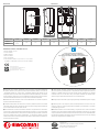
Componenti opzionali
• R284Y021: kit di by-pass dierenziale
• R252Y001: valvola di intercettazione a sfera da G 1”F x calotta G 1-1/2”F,
per installazione a monte del gruppo di distribuzione
Optional components
• R284Y021: differential by-pass kit
• R252Y001: interception ball valve G 1”F x G 1-1/2”F nut,
for installation upstream the distribution unit
Dati tecnici
• Fluidi di impiego: acqua, soluzioni glicolate (max. 50 %)
• Campo di temperatura: 5÷100 °C
• Pressione massima di esercizio: 10 bar
• Attacchi:
- lato impianto: G 1”F
- lato caldaia: G 1-1/2”M
- interasse stacchi: 125 mm
• Peso: 5,8 kg (R586RY101); 4,0 kg (R586RY111)
• Circolatore (per R586RY101) alimentazione elettrica 230 V - 50 Hz, potenza max. 45 W
Technical data
• Fluids: water, glycol-based solutions (max. 50 %)
• Temperature range: 5÷100 °C
• Max. working pressure: 10 for
• Connections:
- system side: G 1”F
- boiler room side: G 1-1/2”M
- outputs centre distance: 125 mm
• Weight: 5,8 kg (R586RY101); 4,0 kg (R586RY111)
• Circulator (for R586RY101) power supply 230 V - 50 Hz, max. power 45 W
Codice
Product code
Applicazione
Use
Reversibilità
mandata/ritorno
Reversibility
delivery/return
Circolatore
Circulator
Miscelazione
Mixing
Valvola miscelatrice
Mixing valve
Attuatore (optional)
Actuator (optional)
R586RY101 Riscaldamento/Rarescamento
Heating/Cooling
Si
Yes DAB EVOSTA2 70/180 -
R586RY111 Riscaldamento/Rarescamento
Heating/Cooling
Si
Yes
Non incluso
Not included -
Versioni e codici Versions and product codes
Circolatori compatibili
• P76DAY001: DAB EVOSTA2 70/180 - interassse 180 mm, attacco G 1-1/2”M
• P76WIY019: Wilo Para 25/9 - interassse 180 mm, attacco G 1-1/2”M
• Grundfos serie Alpha - interassse 180 mm, attacco G 1-1/2”M
Compatible circulators
• P76DAY001: DAB EVOSTA2 70/180 - centre distance 180 mm, connection G 1-1/2”M
• P76WIY019: Wilo Para 25/9 - centre distance 180 mm, connection G 1-1/2”M
• Grundfos Alpha series - centre distance 180 mm, connection G 1-1/2”M
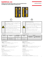
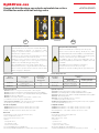
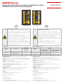
Avvisi di sicurezza e avvertenze
Le presenti istruzioni sono un componente essenziale del prodotto.
Leggere attentamente le istruzioni e le avvertenze in quanto
contengono importanti informazioni per l’istallazione, l’uso e la
manutenzione in completa sicurezza.
Il produttore non sarà responsabile di eventuali danni provocati da un
uso scorretto delle istruzioni o dal loro mancato rispetto.
L’istallazione, la messa in funzione, l’ispezione, la manutenzione
e le riparazioni del gruppo devono essere eseguite da personale
qualicato ed in conformità alle leggi locali/regionali.
Il luogo di installazione deve essere asciutto e riparato dal gelo.
Prima di qualsiasi intervento scollegare l’alimentazione di rete elettrica.
Pericolo di ustioni: prestare attenzione all’acqua calda circolante
all’interno del gruppo e dell’impianto.
Safety information and warnings
This instuction manual is an essential component of the product.
Read the instruction and the warnings carefully as they contain
important information about a safe installation, use and maintenance.
The producer won’t be responsible for damages caused by wrong usage
or unrespect on the instruction given on this manual.
The installation, start up, inspection and maintenance must be
performed by a qualified professional and in compliance with local/
regional laws.
The installation site must be dry and protected from frost.
Before any intervention disconnect the power supply.
Pay attention to hot water circulating within the group and the system.
IT EN
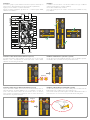
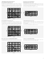
Gruppi di distribuzione senza valvola miscelatrice
Distribution units without mixing valve
R586RY101-111 Istruzioni / Instruction
047U57048 04/2023
R586RY101 R586RY111

2
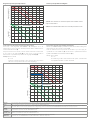
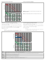
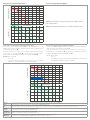
NOTE. Curves obtained with circulator set to “constant speed, level III” mode.
NOTA. Curve ottenute con circolatore impostato sulla modalità “numero
di giri costante, livello III”.
0 0,5 1,5 2,5 4,53,51 2 43
0
1
2
3
4
5
6
7
8
9
R586RY101
P76DAY001
P76WIY019
Flow rate [m3/h]
Prevalenza disponibile a numero di giri costante, livello III
10
20
30
40
50
60
Hydraulic head [mH2O]
Power [kW]
∆t 5
∆t 10
∆t 15
∆t 20
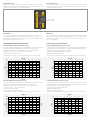
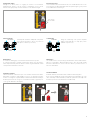
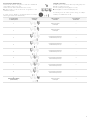
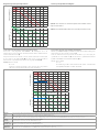
Diagramma di portata/potenza/prevalenza Flow rate/power/hydraulic head diagram
Interpretazione del diagramma di portata/potenza/prevalenza
Conoscendo i dati progettuali della Potenza e Δt dell’impianto che si sta
dimensionando, si traccia una linea orizzontale partendo dall’asse della Potenza no
ad intercettare il Δt richiesto (A).
Dal punto di intersecazione ottenuto, si traccia una linea verticale no ad intercettare
la curva di lavoro del gruppo R586R (B), in questo modo si ricava la portata di
funzionamento e la prevalenza disponibile a valle del gruppo R586R (B, C).
Esempio: Potenza = 20 kW
Δt = 10 °C
Seguendo le indicazioni riportate sopra si ricava un valore di portata di
1,75 m3/h con una prevalenza utile al circolatore di 4,8 mH2O.
Interpretation of ow rate/power/hydraulic head diagram
With the system Power and Δt project data known, trace a horizontal line starting from
the Power axis up to intersecting the required Δt (A).
From the obtained intersection point, trace a vertical line up to intercepting the
operational curve of the R586R unit (B), this will show the operational flow rate and
hydraulic head available downstream the R586R unit (B, C).
Example: Power = 20 kW
Δt = 10 °C
The indications given above will result in a flow rate equal to 1,75 m3/h with a
useful hydraulic head at the circulator of 4,8 mH2O.
1,75 m3/h
4,8 mH2O
0 0,5 1,5 2,5 4,53,51 2 43
0
1
2
3
4
5
6
7
8
9
R586RY101
P76DAY001
P76WIY019
Flow rate [m3/h]
Prevalenza disponibile a numero di giri costante, livello III
10
20
30
40
50
60
Hydraulic head [mH2O]
Power [kW]
∆t 5
∆t 10
∆t 15
∆t 20
A
B
C
Potenza
Power
Potenza richiesta dalla zona dell’impianto di riscaldamento/rarescamento a valle del gruppo di circolazione R586R
Power required by the heating/cooling system zone downstream of the R586R distribution unit
Δt Dierenza di temperatura tra mandata e ritorno della zona dell’impianto di riscaldamento/rarescamento a valle del gruppo di circolazione R586R (il Δt dipende dal tipo di impianto)
Temperature difference between delivery and return of the heating/cooling system zone downstream of the R586R distribution unit (Δt depends on the type of system)
Portata
Flow rate
Portata di funzionamento a valle del gruppo di circolazione R586R
Operational flow rate downstream of the R586R distribution unit
Prevalenza
Hydraulic head
Prevalenza disponibile a valle del gruppo di circolazione R586R
Hydraulic head available downstream of the R586R distribution unit
Curva R586R
R586R curve
Curva di funzionamento del gruppo di circolazione R586R (circolatore Wilo Para + tutti i vari componenti)
Operational curve of the R586R distribution unit (Wilo Para circulator + all various components)

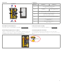
3
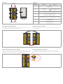
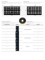
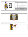
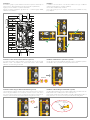
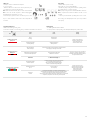
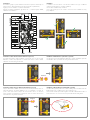
Reversibilità stacchi di mandata/ritorno
Per invertire gli stacchi di mandata e ritorno bisogna semplicemente invertire i due
stacchi incastrandoli nelle sagome della coibentazione.
Delivery/return outputs reversibility
To invert the delivery and return outputs, simply invert these two and slot them into the
insulation templates.
6
5
4
11
2
3
SYSTEM SIDE
BOILER ROOM SIDE
BACK VIEW
7
G 1-1/2”M G 1-1/2”M
G 1”F G 1”F
Riferimento
Reference R586RY101 R586RY111
1Raccordo in ottone
Brass fitting
2Circolatore
Circulator
Tronchetto in acciaio zincato
Spacer in galvanized steel
3Valvola a sfera di mandata, con termometro e attacchi per kit di by-pass
Delivery ball valve with thermometer and by-pass kit connections
4Tronchetto con ritegno integrato
Spacer with integrated check valve
5Valvola a sfera di ritorno con termometro e attacchi per kit di by-pass
Return ball valve with thermometer and by-pass kit connections
6Guscio di coibentazione
Insulation shell
7Piastra per ssaggio a parete
Wall-mount plate
Componenti Components
Valvola di ritegno integrata nello stacco di ritorno
I gruppi sono dotati di valvola di ritegno situata all’interno della parte superiore del
tronchetto in ottone, sullo stacco di ritorno. La valvola di ritegno è eventualmente
smontabile rimuovendo l’anello Seeger usato per ssarla al tronchetto.
Check valve integrated into return output
The units include a check valve inside the brass spacer top, on the return output.
The check valve can be disassembled by removing the Seeger ring used to fit it to the
spacer.
Ritegno
Check valve

4
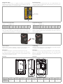
Installazione
Per installare il gruppo a parete utilizzare dei tasselli ad espansione adatti al tipo di
parete ed al peso della strumentazione (tasselli da acquistare separatamente).
Il gruppo può essere installato con qualsiasi orientamento.
Collegare le tubazioni dell’impianto agli attacchi 1”F e 1 1/2”M del gruppo R586R,
utilizzando idonei adattatori.
Installation
To install the unit on a wall use screw anchors suitable for the type of wall and
equipment weight (anchors to purchase separately).
The unit can be installed in any orientation.
Connect the system pipes to the 1”F and 1 1/2”M connections of R586R unit, using
proper adaptors.
Ø 10 mm
Ø 10 mm
1”F
1”F
11/2”M 11/2”M
160 mm
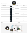
Installazione valvole di intercettazione R252Y001 (optional)
E’ possibile intercettare il gruppo installando a monte dello stesso le valvole a sfera
R252Y001 (1 1/2”F x 1”F). L’apertura e la chiusura delle valvole a sfera si eettua
utilizzando una chiave a brugola da 5 mm.
Installation of R252Y001 interception valves (optional)
The unit can be intercepted by installing the R252Y001 (1 1/2”F x 1”F) ball valves upstream.
The ball valves can be opened and closed using a 5 mm Allen wrench.
R252Y001
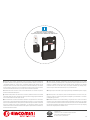
Installazione del kit di by-pass dierenziale R284Y021 (optional)
Il by-pass dierenziale è utilizzato a protezione del circolatore permettendo il ricircolo
dell’acqua all’interno del gruppo R586R nel caso in cui l’impianto secondario sia
spento o tutto chiuso. Il kit è composto da un tronchetto in ottone con valvola di
ritegno integrata con taratura ssa a 5 mH2O, due calotte da avvitare alle valvole di
intercettazione e due guarnizioni in PTFE.
Installation of dierential by-pass kit R284Y021 (optional)
The differential by-pass kit protects the circulator enabling water recirculation inside the
R586R unit when the secondary system is off or completely closed.
The kit includes a brass spacer with integrated check valve calibrated at a fix value of
5 mH2O, two nuts to be screwed on the interception valves and two PTFE gaskets.
R284Y021
Guarnizione
Gasket
Ritegno
Check valve
Calotta
Nut

5
Manutenzione
In condizioni normali il gruppo non richiede alcuna manutenzione specica.
E’ comunque importante controllare periodicamente, almeno una volta all’anno,
l’intero impianto. Prestare particolare attenzione a tutti i collegamenti lettati o saldati
e alla potenziale sedimentazione di calcare.
Maintenance
The circulation unit does not require any specific maintenance under normal conditions.
Althoug it is important to almost annually check the entire system. Pay specially
attention to all threaded or soldered connections and the potential occurrence of
limestone sedimentation.
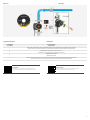
Collegamenti elettrici
Collegare il cavo Molex, incluso con il gruppo, al circolatore e successivamente
all’alimentazione elettrica. I cavi del circolatore possono passare all’interno delle guide
predisposte nella coibentazione come illustrato in gura.
Electrical connections
Connect the Molex cable, included with the unit, to the circulator and then to the
electric power supply. The circulator cables can pass through the guides provided in the
insulation as shown in the figure.
Cavi elettrici
Electric cables
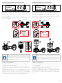
FUNZIONAMENTO CIRCOLATORE DAB EVOSTA2 DAB EVOSTA2 CIRCULATOR OPERATION
Pressione dierenziale proporzionale Δp-v (I, II, III)
In questa modalità di regolazione la pressione dierenziale viene ridotta o aumenta al
diminuire o all’aumentare della richiesta d’acqua. Regolazione indicata per:
• Impianti di riscaldamento e condizionamento con elevate perdite di carico
• Impianti con regolatore di pressione dierenziale secondario
• Circuiti primari con alte perdite di carico
• Sistemi di ricircolo sanitario con valvole termostatiche sulle colonne montanti
Proportional dierential pressure Δp-v (I, II, III)
In this regulating mode the differential pressure is reduced or increased as the demand for water
decreases or increases. The Hs set point may be set from the display. Regulation indicated for:
• Heating and conditioning plants with high load losses
• Plants with secondary differential pressure regulator
• Primary circuits with high load losses
• Domestic water recirculating systems with thermostatic valves on the rising columns
Curva costante
H [m]
0 0,45 0,9 1,36 1,82 2,27 2,73 3,18 3,63 4,09
0 2 4 6 8 10 12 14 16 18
Q [m3/h]
0 0,45 0,9 1,36 1,82 2,27 2,73 3,18 3,63
Q [m3/h]
Q [gpm]
0 2 4 6 8 10 12 14 16
Q [gpm]
0
0
5
10
15
20
25
30
35
40
45
0,61
1,22
1,83
2,43
3,05
3,66
4,27
4,88
5,49
6,10
H [ft]
0
2
4
6
8
10
12
14
16
18
20
P [W]
Pressione Differenziale Proporzionale
H [m]
0 0,45 0,9 1,36 1,82 2,27 2,73 3,18 3,63 4,09
0 2 4 6 8 10 12 14 16 18
Q [m3/h]
0 0,45 0,9 1,36 1,82 2,27 2,73 3,18 3,63
Q [m3/h]
Q [gpm]
0 2 4 6 8 10 12 14 16
Q [gpm]
0
0
5
10
15
20
25
30
35
40
45
0,61
1,22
1,83
2,43
3,05
3,66
4,27
4,88
5,49
6,10
H [ft]
0
2
4
6
8
10
12
14
16
18
20
P [W]
Pressione Differenziale Costante
H [m]
0 0,45 0,9 1,36 1,82 2,27 2,73 3,18 3,63 4,09
0 2 4 6 8 10 12 14 16 18
Q [m3/h]
0 0,45 0,9 1,36 1,82 2,27 2,73 3,18 3,63
Q [m3/h]
Q [gpm]
0 2 4 6 8 10 12 14 16
Q [gpm]
0
0
5
10
15
20
25
30
35
40
45
0,61
1,22
1,83
2,43
3,05
3,66
4,27
4,88
5,49
6,10
H [ft]
0
2
4
6
8
10
12
14
16
18
20
P [W]
Curva costante
H [m]
0 0,45 0,9 1,36 1,82 2,27 2,73 3,18 3,63 4,09
0 2 4 6 8 10 12 14 16 18
Q [m3/h]
0 0,45 0,9 1,36 1,82 2,27 2,73 3,18 3,63
Q [m3/h]
Q [gpm]
0 2 4 6 8 10 12 14 16
Q [gpm]
0
0
5
10
15
20
25
30
35
40
45
0,61
1,22
1,83
2,43
3,05
3,66
4,27
4,88
5,49
6,10
H [ft]
0
2
4
6
8
10
12
14
16
18
20
P [W]
Pressione Differenziale Proporzionale
H [m]
0 0,45 0,9 1,36 1,82 2,27 2,73 3,18 3,63 4,09
0 2 4 6 8 10 12 14 16 18
Q [m3/h]
0 0,45 0,9 1,36 1,82 2,27 2,73 3,18 3,63
Q [m
3
/h]
Q [gpm]
0 2 4 6 8 10 12 14 16
Q [gpm]
0
0
5
10
15
20
25
30
35
40
45
0,61
1,22
1,83
2,43
3,05
3,66
4,27
4,88
5,49
6,10
H [ft]
0
2
4
6
8
10
12
14
16
18
20
P [W]
Pressione Differenziale Costante
H [m]
0 0,45 0,9 1,36 1,82 2,27 2,73 3,18 3,63 4,09
0 2 4 6 8 10 12 14 16 18
Q [m3/h]
0 0,45 0,9 1,36 1,82 2,27 2,73 3,18 3,63
Q [m3/h]
Q [gpm]
0 2 4 6 8 10 12 14 16
Q [gpm]
0
0
5
10
15
20
25
30
35
40
45
0,61
1,22
1,83
2,43
3,05
3,66
4,27
4,88
5,49
6,10
H [ft]
0
2
4
6
8
10
12
14
16
18
20
P [W]
Pressione dierenziale costante Δp-c (I, II, III)
In questa modalità di regolazione la pressione dierenziale viene mantenuta costante,
indipendentemente dalla richiesta d’acqua. Regolazione indicata per:
• Impianti di riscaldamento e condizionamento con basse perdite di carico
• Sistemi monotubo con valvole termostatiche
• Impianti a circolazione naturale
• Circuiti primari con basse perdite di carico
• Sistemi di ricircolo sanitario con valvole termostatiche sulle colonne montanti
Constant dierential pressure Δp-c (I, II, III)
In this regulating mode the differential pressure is kept constant, irrespective of the
demand for water, The Hs set point may be set from the display. Regulation indicated for:
• Heating and conditioning plants with low load losses
• Single-pipe systems with thermostatic valves
• Plants with natural circulation
• Primary circuits with low load losses
• Domestic water recirculating systems with thermostatic valves on the rising columns
Curva costante
H [m]
0 0,45 0,9 1,36 1,82 2,27 2,73 3,18 3,63 4,09
0 2 4 6 8 10 12 14 16 18
Q [m3/h]
0 0,45 0,9 1,36 1,82 2,27 2,73 3,18 3,63
Q [m3/h]
Q [gpm]
0 2 4 6 8 10 12 14 16
Q [gpm]
0
0
5
10
15
20
25
30
35
40
45
0,61
1,22
1,83
2,43
3,05
3,66
4,27
4,88
5,49
6,10
H [ft]
0
2
4
6
8
10
12
14
16
18
20
P [W]
Pressione Differenziale Proporzionale
H [m]
0 0,45 0,9 1,36 1,82 2,27 2,73 3,18 3,63 4,09
0 2 4 6 8 10 12 14 16 18
Q [m3/h]
0 0,45 0,9 1,36 1,82 2,27 2,73 3,18 3,63
Q [m3/h]
Q [gpm]
0 2 4 6 8 10 12 14 16
Q [gpm]
0
0
5
10
15
20
25
30
35
40
45
0,61
1,22
1,83
2,43
3,05
3,66
4,27
4,88
5,49
6,10
H [ft]
0
2
4
6
8
10
12
14
16
18
20
P [W]
Pressione Differenziale Costante
H [m]
0 0,45 0,9 1,36 1,82 2,27 2,73 3,18 3,63 4,09
0 2 4 6 8 10 12 14 16 18
Q [m3/h]
0 0,45 0,9 1,36 1,82 2,27 2,73 3,18 3,63
Q [m3/h]
Q [gpm]
0 2 4 6 8 10 12 14 16
Q [gpm]
0
0
5
10
15
20
25
30
35
40
45
0,61
1,22
1,83
2,43
3,05
3,66
4,27
4,88
5,49
6,10
H [ft]
0
2
4
6
8
10
12
14
16
18
20
P [W]
Curva costante
H [m]
0 0,45 0,9 1,36 1,82 2,27 2,73 3,18 3,63 4,09
0 2 4 6 8 10 12 14 16 18
Q [m3/h]
0 0,45 0,9 1,36 1,82 2,27 2,73 3,18 3,63
Q [m3/h]
Q [gpm]
0 2 4 6 8 10 12 14 16
Q [gpm]
0
0
5
10
15
20
25
30
35
40
45
0,61
1,22
1,83
2,43
3,05
3,66
4,27
4,88
5,49
6,10
H [ft]
0
2
4
6
8
10
12
14
16
18
20
P [W]
Pressione Differenziale Proporzionale
H [m]
0 0,45 0,9 1,36 1,82 2,27 2,73 3,18 3,63 4,09
0 2 4 6 8 10 12 14 16 18
Q [m3/h]
0 0,45 0,9 1,36 1,82 2,27 2,73 3,18 3,63
Q [m3/h]
Q [gpm]
0 2 4 6 8 10 12 14 16
Q [gpm]
0
0
5
10
15
20
25
30
35
40
45
0,61
1,22
1,83
2,43
3,05
3,66
4,27
4,88
5,49
6,10
H [ft]
0
2
4
6
8
10
12
14
16
18
20
P [W]
Pressione Differenziale Costante
H [m]
0 0,45 0,9 1,36 1,82 2,27 2,73 3,18 3,63 4,09
0 2 4 6 8 10 12 14 16 18
Q [m3/h]
0 0,45 0,9 1,36 1,82 2,27 2,73 3,18 3,63
Q [m
3
/h]
Q [gpm]
0 2 4 6 8 10 12 14 16
Q [gpm]
0
0
5
10
15
20
25
30
35
40
45
0,61
1,22
1,83
2,43
3,05
3,66
4,27
4,88
5,49
6,10
H [ft]
0
2
4
6
8
10
12
14
16
18
20
P [W]

6
Curva costante (I, II, III)
In questa modalità di regolazione il circolatore lavora su curve caratteristiche a velocità
costante. Regolazione indicata per impianti di riscaldamento e condizionamento a
portata costante.
Constant curve (I, II, III)
In this regulating mode the circulator works on characteristic curves at a constant speed.
Regulation indicated for heating and conditioning plants with constant flow.
Curva costante
H [m]
0 0,45 0,9 1,36 1,82 2,27 2,73 3,18 3,63 4,09
0 2 4 6 8 10 12 14 16 18
Q [m
3
/h]
0 0,45 0,9 1,36 1,82 2,27 2,73 3,18 3,63
Q [m3/h]
Q [gpm]
0 2 4 6 8 10 12 14 16
Q [gpm]
0
0
5
10
15
20
25
30
35
40
45
0,61
1,22
1,83
2,43
3,05
3,66
4,27
4,88
5,49
6,10
H [ft]
0
2
4
6
8
10
12
14
16
18
20
P [W]
Pressione Differenziale Proporzionale
H [m]
0 0,45 0,9 1,36 1,82 2,27 2,73 3,18 3,63 4,09
0 2 4 6 8 10 12 14 16 18
Q [m3/h]
0 0,45 0,9 1,36 1,82 2,27 2,73 3,18 3,63
Q [m3/h]
Q [gpm]
0 2 4 6 8 10 12 14 16
Q [gpm]
0
0
5
10
15
20
25
30
35
40
45
0,61
1,22
1,83
2,43
3,05
3,66
4,27
4,88
5,49
6,10
H [ft]
0
2
4
6
8
10
12
14
16
18
20
P [W]
Pressione Differenziale Costante
H [m]
0 0,45 0,9 1,36 1,82 2,27 2,73 3,18 3,63 4,09
0 2 4 6 8 10 12 14 16 18
Q [m3/h]
0 0,45 0,9 1,36 1,82 2,27 2,73 3,18 3,63
Q [m3/h]
Q [gpm]
0 2 4 6 8 10 12 14 16
Q [gpm]
0
0
5
10
15
20
25
30
35
40
45
0,61
1,22
1,83
2,43
3,05
3,66
4,27
4,88
5,49
6,10
H [ft]
0
2
4
6
8
10
12
14
16
18
20
P [W]
Curva costante
H [m]
0 0,45 0,9 1,36 1,82 2,27 2,73 3,18 3,63 4,09
0 2 4 6 8 10 12 14 16 18
Q [m3/h]
0 0,45 0,9 1,36 1,82 2,27 2,73 3,18 3,63
Q [m
3
/h]
Q [gpm]
0 2 4 6 8 10 12 14 16
Q [gpm]
0
0
5
10
15
20
25
30
35
40
45
0,61
1,22
1,83
2,43
3,05
3,66
4,27
4,88
5,49
6,10
H [ft]
0
2
4
6
8
10
12
14
16
18
20
P [W]
Pressione Differenziale Proporzionale
H [m]
0 0,45 0,9 1,36 1,82 2,27 2,73 3,18 3,63 4,09
0 2 4 6 8 10 12 14 16 18
Q [m3/h]
0 0,45 0,9 1,36 1,82 2,27 2,73 3,18 3,63
Q [m3/h]
Q [gpm]
0 2 4 6 8 10 12 14 16
Q [gpm]
0
0
5
10
15
20
25
30
35
40
45
0,61
1,22
1,83
2,43
3,05
3,66
4,27
4,88
5,49
6,10
H [ft]
0
2
4
6
8
10
12
14
16
18
20
P [W]
Pressione Differenziale Costante
H [m]
0 0,45 0,9 1,36 1,82 2,27 2,73 3,18 3,63 4,09
0 2 4 6 8 10 12 14 16 18
Q [m3/h]
0 0,45 0,9 1,36 1,82 2,27 2,73 3,18 3,63
Q [m3/h]
Q [gpm]
0 2 4 6 8 10 12 14 16
Q [gpm]
0
0
5
10
15
20
25
30
35
40
45
0,61
1,22
1,83
2,43
3,05
3,66
4,27
4,88
5,49
6,10
H [ft]
0
2
4
6
8
10
12
14
16
18
20
P [W]
N° pressioni pulsante MODE
N° of MODE button pressures
Indicatore LED
LED display
Modo di regolazione
Control mode
Curva caratteristica
Circulator curve
1
Pressione differenziale proporzionale Δp-v
Proportional differential pressure Δp-v
I
2II
3III
4
Pressione differenziale costante Δp-c
Constant differential pressure Δp-c
I
5II
6III
7
Numero di giri costante
Constant speed
I
8II
9III
Impostare il modo di funzionameto
La modalità di funzionamento del circolatore può essere modicata
tramite il pannello di controllo posto sul coperchio frontale.
Setting the control mode
The operating mode of the circulator can be changed using the control
panel located on the front cover.

7
Segnalazioni di allarmi
N° di lampeggi
Nr. of blinking
Descrizione allarme
Fault description
2TRIP: perdita controllo motore, può essere causata da parametri errati, rotore bloccato, fase sconnessa, motore sconnesso
TRIP: loss of motor control, may be caused by incorrect parameters, blocked rotor, disconnected phase, disconnected motor
3SHORT CIRCUIT: corto circuito su fasi o tra fase e terra
SHORT CIRCUIT: short circuit on phases or between phase and earth
4OVERRUN: guasto software
OVERRUN: software fault
5SAFETY: errore modulo di sicurezza, può essere causato da una sovracorrente imprevista o altri guasti hardware della scheda
SAFETY: safety module error, may be caused by a sudden overcurrent or other hardware faults of the board
Fault signals
Sato aria Air venting
ISTRUZIONI
Inquadra con lo smartphone o il tablet il QR-Code
per visualizzare le istruzioni complete del circolatore.
INSTRUCTIONS
Frame the QR code with your smartphone or tablet
to view the complete circulator instruction.

8
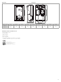
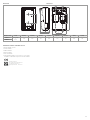
Dimensioni Dimensions
L
F
E
HC
D
G
I
B B
A A
Ø10
Ø10
Codice - Code A x B C [mm] D [mm] E [mm] F [mm] G [mm] H [mm] I [mm] L [mm]
R586RY101 G 1-1/2”M
x
G 1”F
125 250 180 430 100 65 165 160
R586RY111
Conserva le presenti istruzioni all’interno
della coibentazione del gruppo di distribuzione.
Keep this instruction inside the insulation of the distribution unit.
Istruzioni
Instruction
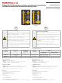
Avvertenze per la sicurezza. L’installazione, la messa in servizio e la periodica manutenzione
del prodotto devono essere eseguite da personale professionalmente abilitato, in accordo con
i regolamenti nazionali e/o i requisiti locali. L’installatore qualicato deve adottare tutti gli
accorgimenti necessari, incluso l’utilizzo di Dispositivi di Protezione Individuale, per assicurare la
propria incolumità e quella di terzi. L’errata installazione può causare danni a persone, animali o
cose nei confronti dei quali Giacomini S.p.A. non può essere considerata responsabile.
Safety Warning. Installation, commissioning and periodical maintenance of the product
must be carried out by qualied operators in compliance with national regulations and/or local
standards. A qualied installer must take all required measures, including use of Individual
Protection Devices, for his and others’ safety. An improper installation may damage people,
animals or objects towards which Giacomini S.p.A. may not be held liable.
Smaltimento imballo. Scatole in cartone: raccolta differenziata carta. Sacchetti in plastica e
pluriball: raccolta differenziata plastica.
Package Dispos al. Car ton boxes: paper re cycling. Plast ic bags and bubble wrap: plastic recycling.
Smaltimento del prodotto. Alla ne del suo ciclo di vita il prodotto non deve essere smaltito
come riuto urbano. Può essere portato ad un centro speciale di riciclaggio gestito dall’autorità
locale o ad un rivenditore che offre questo servizio.
Product Disposal. Do not dispose of product as municipal waste at the end of its life cycle.
Dispose of product at a special recycling platform managed by local authorities or at retailers
providing this type of service.
Altre informazioni. Per ulteriori informazioni consultare il sito giacomini.com o contattare il
servizio tecnico. Questa comunicazione ha valore indicativo. Giacomini S.p.A. si riserva il diritto di
apportare in qualunque momento, senza preavviso, modiche per ragioni tecniche o commerciali
agli articoli contenuti nella presente comunicazione. Le informazioni contenute in questa
comunicazione tecnica non esentano l’utilizzatore dal seguire scrupolosamente le normative e le
norme di buona tecnica esistenti.
Additional information. For more information, go to giacomini.com or contact our technical
assistance service. This document provides only general indications. Giacomini S.p.A. may change
at any time, without notice and for technical or commercial reasons, the items included herewith.
The information included in this technical sheet do not exempt the user from strictly complying
with the rules and good practice standards in force.
Riferimenti normativi - Standards reference
• PED 2014/68/EU, par. 4.3
• LVD 2014/35/EU
• EMC 2014/30/EU
• ErP 2009/125/EU
• RoHS 2011/65/EU
• Conformità CE e UKCA: solo per versioni con circolatore
Compliance CE and UKCA: only for versions with circulator
Imported by GIACOMINI U.K.
Unit 2, Goodrich Close, Westerleigh Business Park,
Yate, South Gloucestershire, BS37 5YT.
support@giacomini.co.uk 01454311012
Giacomini S.p.A.
Via per Alzo 39, 28017 San Maurizio d’Opaglio (NO) Italia
consulenza.prodotti@giacomini.com
+39 0322 923372 - giacomini.com

1
Componenti opzionali
• K275Y002: attuatore con regolatore di temperatura costante integrato
• K275Y011: attuatore 3 punti ottante comandabile tramite termoregolaz. KLIMAbus
• K275Y013: attuatore con controllo 0...10 V comandabile tramite termoregolaz. KLIMAbus
• R284Y021: kit di by-pass dierenziale
• R252Y001: valvola di intercettazione a sfera da G 1”F x calotta G 1-1/2”F,
per installazione a monte del gruppo di distribuzione
• Termoregolazione KLIMAbus: componenti di termoregolazione KLIMAbus
(modulo di regolazione, termostati, sonde ambiente, ecc...)
Optional components
• K275Y002: actuator with integrated constant temperature regulator
• K275Y011: 3-point floating actuator controllable with KLIMAbus thermoregulation
• K275Y013: actuator with 0...10 V regulation controllable with KLIMAbus thermoregulation
• R284Y021: differential by-pass kit
• R252Y001: interception ball valve G 1”F x G 1-1/2”F nut,
for installation upstream the distribution unit
• KLIMAbus thermoregulation: KLIMAbus thermoregulation components (regulation
unit, thermostats, ambient probes, etc...)
Dati tecnici
• Fluidi di impiego: acqua, soluzioni glicolate (max. 50 %)
• Campo di temperatura: 5÷100 °C
• Pressione massima di esercizio: 10 bar
• Attacchi:
- lato impianto: G 1”F
- lato caldaia: G 1-1/2”M
- interasse stacchi: 125 mm
• Peso: 6,8 kg (R586RY102); 5,0 kg (R586RY112)
• Circolatore (per R586RY102) alimentazione elettrica 230 V - 50 Hz, potenza max. 45 W
Technical data
• Fluids: water, glycol-based solutions (max. 50 %)
• Temperature range: 5÷100 °C
• Max. working pressure: 10 bar
• Connections:
- system side: G 1”F
- boiler room side: G 1-1/2”M
- outputs centre distance: 125 mm
• Weight: 6,8 kg (R586RY102); 5,0 kg (R586RY112)
• Circulator (for R586RY102) power supply 230 V - 50 Hz, max. power 45 W
Codice
Product code
Applicazione
Use
Reversibilità
mandata/ritorno
Reversibility
delivery/return
Circolatore
Circulator
Miscelazione
Mixing
Valvola miscelatrice
Mixing valve
Attuatore (optional)
Actuator (optional)
R586RY102 Riscaldamento/Rarescamento
Heating/Cooling
Si
Yes Wilo Para 25/6 Miscelatrice a sfera (R296)
Ball mixing valve (R296) K275Y002/011/013
R586RY112 Riscaldamento/Rarescamento
Heating/Cooling
Si
Yes
Non incluso
Not included
Miscelatrice a sfera (R296)
Ball mixing valve (R296) K275Y002/011/013
Versioni e codici Versions and product codes
Avvisi di sicurezza e avvertenze
Le presenti istruzioni sono un componente essenziale del prodotto.
Leggere attentamente le istruzioni e le avvertenze in quanto
contengono importanti informazioni per l’istallazione, l’uso e la
manutenzione in completa sicurezza.
Il produttore non sarà responsabile di eventuali danni provocati da un
uso scorretto delle istruzioni o dal loro mancato rispetto.
L’istallazione, la messa in funzione, l’ispezione, la manutenzione
e le riparazioni del gruppo devono essere eseguite da personale
qualicato ed in conformità alle leggi locali/regionali.
Il luogo di installazione deve essere asciutto e riparato dal gelo.
Prima di qualsiasi intervento scollegare l’alimentazione di rete elettrica.
Pericolo di ustioni: prestare attenzione all’acqua calda circolante
all’interno del gruppo e dell’impianto.
Safety information and warnings
This instuction manual is an essential component of the product.
Read the instruction and the warnings carefully as they contain
important information about a safe installation, use and maintenance.
The producer won’t be responsible for damages caused by wrong usage
or unrespect on the instruction given on this manual.
The installation, start up, inspection and maintenance must be
performed by a qualified professional and in compliance with local/
regional laws.
The installation site must be dry and protected from frost.
Before any intervention disconnect the power supply.
Pay attention to hot water circulating within the group and the system.
IT EN
Gruppi di distribuzione con valvola miscelatrice a sfera
Distribution units with ball mixing valve
R586RY102-112 Istruzioni / Instruction
047U57378 09/2022
R586RY102 R586RY112
Circolatori compatibili
• P76WIY017: Wilo Para 25/7 - interassse 180 mm, attacco G 1-1/2”M
• P76WIY019: Wilo Para 25/9 - interassse 180 mm, attacco G 1-1/2”M
• Grundfos serie Alpha - interassse 180 mm, attacco G 1-1/2”M
Compatible circulators
• P76WIY017: Wilo Para 25/7 - centre distance 180 mm, connection G 1-1/2”M
• P76WIY019: Wilo Para 25/9 - centre distance 180 mm, connection G 1-1/2”M
• Grundfos Alpha series - centre distance 180 mm, connection G 1-1/2”M

2
NOTE. Curves obtained with circulator set to “constant speed, level III” mode.
NOTA. Curve ottenute con circolatore impostato sulla modalità “numero
di giri costante, livello III”.
0
1
2
3
4
5
6
7
8
9
0 0,5 1
1,5
H - m
Port
ata
Nuovi gruppi R586R: pr
evalenza disponibile velocità costante, livello III
0 0,5 1,5 2,5 4,53,51 2 43
0
1
2
3
4
5
6
7
8
9
R586RY102
P76WIY017
P76WIY019
Flow rate [m3/h]
Prevalenza disponibile a numero di giri costante, livello III
10
20
30
40
50
60
Hydraulic head [mH2O]
Power [kW]
∆t 5
∆t 10
∆t 15
∆t 20
0
1
2
3
4
5
6
7
8
9
0 0,5 1 1,5 2
H - m
Portata
Gruppi R586R: prevalenza disponibile con circolatore WILO PARA 25
Diagramma di portata/potenza/prevalenza Flow rate/power/hydraulic head diagram
Interpretazione del diagramma di portata/potenza/prevalenza
Conoscendo i dati progettuali della Potenza e Δt dell’impianto che si sta
dimensionando, si traccia una linea orizzontale partendo dall’asse della Potenza no
ad intercettare il Δt richiesto (A).
Dal punto di intersecazione ottenuto, si traccia una linea verticale no ad intercettare
la curva di lavoro del gruppo R586R (B), in questo modo si ricava la portata di
funzionamento e la prevalenza disponibile a valle del gruppo R586R (B, C).
Esempio: Potenza = 20 kW
Δt = 10 °C
Seguendo le indicazioni riportate sopra si ricava un valore di portata di
1,75 m3/h con una prevalenza utile al circolatore di 4,6 mH2O.
Interpretation of ow rate/power/hydraulic head diagram
With the system Power and Δt project data known, trace a horizontal line starting from
the Power axis up to intersecting the required Δt (A).
From the obtained intersection point, trace a vertical line up to intercepting the
operational curve of the R586R unit (B), this will show the operational flow rate and
hydraulic head available downstream the R586R unit (B, C).
Example: Power = 20 kW
Δt = 10 °C
The indications given above will result in a flow rate equal to 1,75 m3/h with a
useful hydraulic head at the circulator of 4,6 mH2O.
1,75 m3/h
4,6 mH2O
0 0,5 1,5 2,5 4,53,51 2 43
0
1
2
3
4
5
6
7
8
9
R586RY102
P76WIY017
P76WIY019
Flow rate [m3/h]
Prevalenza disponibile a numero di giri costante, livello III
10
20
30
40
50
60
Hydraulic head [mH2O]
Power [kW]
∆t 5
∆t 10
∆t 15
∆t 20
A
B
C
Potenza
Power
Potenza richiesta dalla zona dell’impianto di riscaldamento/rarescamento a valle del gruppo di circolazione R586R
Power required by the heating/cooling system zone downstream of the R586R distribution unit
Δt Dierenza di temperatura tra mandata e ritorno della zona dell’impianto di riscaldamento/rarescamento a valle del gruppo di circolazione R586R (il Δt dipende dal tipo di impianto)
Temperature difference between delivery and return of the heating/cooling system zone downstream of the R586R distribution unit (Δt depends on the type of system)
Portata
Flow rate
Portata di funzionamento a valle del gruppo di circolazione R586R
Operational flow rate downstream of the R586R distribution unit
Prevalenza
Hydraulic head
Prevalenza disponibile a valle del gruppo di circolazione R586R
Hydraulic head available downstream of the R586R distribution unit
Curva R586R
R586R curve
Curva di funzionamento del gruppo di circolazione R586R (circolatore Wilo Para + tutti i vari componenti)
Operational curve of the R586R distribution unit (Wilo Para circulator + all various components)

3
6
5
4
1
2
3
SYSTEM SIDE
BOILER ROOM SIDE
7
G 1-1/2”M G 1-1/2”M
G 1”F G 1”F
Riferimento
Reference R586RY101 R586RY111
1Valvola miscelatrice a sfera (R296)
Mixing ball valve (R296)
2Circolatore
Circulator
Tronchetto in acciaio zincato
Spacer in galvanized steel
3Valvola a sfera di mandata, con termometro e attacchi per kit di by-pass
Delivery ball valve with thermometer and by-pass kit connections
4Tronchetto con ritegno integrato
Spacer with integrated check valve
5Valvola a sfera di ritorno con termometro e attacchi per kit di by-pass
Return ball valve with thermometer and by-pass kit connections
6Guscio di coibentazione
Insulation shell
7Piastra per ssaggio a parete
Wall-mount plate
Componenti Components
Reversibilità stacchi di mandata/ritorno
Invertire la mandata con il ritorno incastrando gli stacchi nelle sagome della
coibentazione. Invertire anche il tappo e il raccordo di rame della valvola miscelatrice.
Delivery/return outputs reversibility
Invert delivery and return by fitting the outputs in the insulation slots.
Also invert the cap and the copper fitting of the mixing valve.
Valvola di ritegno integrata nello stacco di ritorno
I gruppi sono dotati di valvola di ritegno situata all’interno della parte superiore del
tronchetto in ottone, sullo stacco di ritorno. La valvola di ritegno è eventualmente
smontabile rimuovendo l’anello Seeger usato per ssarla al tronchetto.
Check valve integrated into return output
The units include a check valve inside the brass spacer top, on the return output.
The check valve can be disassembled by removing the Seeger ring used to fit it to the
spacer.
Ritegno
Check valve

4
Installazione
Per installare il gruppo a parete utilizzare dei tasselli ad espansione adatti al tipo di
parete ed al peso della strumentazione (tasselli da acquistare separatamente).
Il gruppo può essere installato con qualsiasi orientamento.
Collegare le tubazioni dell’impianto agli attacchi 1”F e 1 1/2”M del gruppo R586R,
utilizzando idonei adattatori.
Installation
To install the unit on a wall use screw anchors suitable for the type of wall and
equipment weight (anchors to purchase separately).
The unit can be installed in any orientation.
Connect the system pipes to the 1”F and 1 1/2”M connections of R586R unit, using
proper adaptors.
Ø 10 mm
Ø 10 mm
1”F
1”F
160 mm
11/2”M 11/2”M
Installazione valvole di intercettazione R252Y001 (optional)
E’ possibile intercettare il gruppo installando a monte dello stesso le valvole a sfera
R252Y001 (1-1/2”F x 1”F). L’apertura e la chiusura delle valvole a sfera si eettua
utilizzando una chiave a brugola da 5 mm.
Installation of R252Y001 interception valves (optional)
The unit can be intercepted by installing the R252Y001 (1-1/2”F x 1”F) ball valves upstream.
The ball valves can be opened and closed using a 5 mm Allen wrench.
R252Y001
Installazione del kit di by-pass dierenziale R284Y021 (optional)
Il by-pass dierenziale è utilizzato a protezione del circolatore permettendo il ricircolo dell’acqua
all’interno del gruppo R586R nel caso in cui l’impianto secondario sia spento o tutto chiuso. Il
kit è composto da un tronchetto in ottone con valvola di ritegno integrata con taratura ssa a 5
mH2O, due calotte da avvitare alle valvole di intercettazione e due guarnizioni in PTFE.
Installation of dierential by-pass kit R284Y021 (optional)
The differential by-pass kit protects the circulator enabling water recirculation inside the
R586R unit when the secondary system is off or completely closed.
The kit includes a brass spacer with integrated check valve calibrated at a fix value of
5 mH2O, two nuts to be screwed on the interception valves and two PTFE gaskets.
R284Y021
Guarnizione
Gasket
Ritegno
Check valve
Calotta
Nut

5
Manutenzione
In condizioni normali il gruppo non richiede alcuna manutenzione specica.
E’ comunque importante controllare periodicamente, almeno una volta all’anno,
l’intero impianto. Prestare particolare attenzione a tutti i collegamenti lettati o saldati
e alla potenziale sedimentazione di calcare.
Maintenance
The circulation unit does not require any specific maintenance under normal conditions.
Althoug it is important to almost annually check the entire system. Pay specially
attention to all threaded or soldered connections and the potential occurrence of
limestone sedimentation.
Primo avviamento
LATO IMPIANTO
LATO CENTRALE
TERMICA
LATO IMPIANTO
LATO CENTRALE
TERMICA
Durante il primo avviamento dell’impianto è importante
che la valvola miscelatrice a sfera sia in posizione di
Tutto Aperto (volantino in posizione “5”).
Commisioning
SYSTEM SIDE
BOILER ROOM
SIDE
SYSTEM SIDE
BOILER ROOM
SIDE
During the commisioning of the system is important
that the mixing ball valve is in Fully Open position
(handwheel in position “5”).
Collegamenti elettrici
Collegare il cavo Molex, incluso con il gruppo, al circolatore e successivamente
all’alimentazione elettrica. I cavi del circolatore e dell’attuatore possono passare
all’interno delle guide predisposte nella coibentazione come illustrato in gura.
Electrical connections
Connect the Molex cable, included with the unit, to the circulator and then to the electric
power supply. The circulator and actuator cables can pass through the guides provided
in the insulation as shown in the figure.
Cavi elettrici
Electric cables
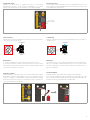
Installazione attuatore
L’attuatore K275Y002 o K275Y011/013 può essere installato sulla valvola miscelatrice
R296. Prima di chiudere il gruppo R586R con il guscio di coibentazione frontale,
inciderlo con un taglierino con punta alata, creando la forma dell’attuatore K275 (per
facilitare l’operazione il retro del guscio di coibentazione frontale è già predisposto
con la sagoma dell’attuatore da ritagliare).
Actuator installation
K275Y002 or K275Y011/013 actuators can be installed on R296 mixing valves.
Before closing the R586R unit with the front insulation shell, with a sharp-edge cutter
carve out the shape of the K275 actuator (to make this operation easier, the shape of the
actuator is reproduced on the back of the front insulation shell).

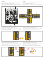
6
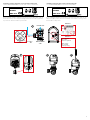
Installation of K275Y002 actuator on R296 mixing valve
Use the Connection kit 0296 included in the actuator package.
Before installing the K275Y002 actuator on the R296 mixing valve, make sure the valve
is in by-pass position (milling in OFF position) and the actuator is in closing position.
With the valve body on the left and the by-pass T-shaped fitting on the right, the DIP1
must be positioned on OFF (1a).
With the valve body on the right and the by-pass T-shaped fitting on the left, the DIP1
must be positioned on ON (1b).
Note.
When the DIP1 position is changed, actuator calibration begins. The LED blinks
(1x/sec) and the actuator is turned right and left. When this happens, leave the
actuator in the AUTO position, do not change the settings and do not cut off
electric power. When calibrating the actuator, to protect the system, the circulator
must be turned off to prevent temperature fluctuations in the system.
Installation of temperature probes
The temperature probe must be installed after the system circulator, at a max. distance
of 1,5 m from the actuator.
• For contact installation, use the kit included with the actuator. This requires a flat
surface with a min. length of 40 mm to position the probe.
• For immersion installation, the probe must be installed in a housing up to half of the
piping diameter (the R227Y003 housing can be used by installing it in the ball valve
sockets included with the R586R unit). This requires a suitable mechanic protection
of the probe and probe wire. The wire must be insulated in case of contact with very
hot parts.
Installazione attuatore K275Y002 su valvola miscelatrice R296
Utilizzare il Connection kit 0296 contenuto nella confezione dell’attuatore.
Prima di installare l’attuatore K275Y002 sulla valvola miscelatrice R296, vericare che la
valvola sia in posizione di by-pass (fresatura in posizione OFF) e l’attuatore in posizione
di chiusura.
Con il corpo valvola a sinistra e il raccordo a T di by-pass a destra, il DIP1 deve essere
posizionato su OFF (1a).
Con il corpo valvola a destra e il raccordo a T di by-pass a sinistra, il DIP1 deve essere
posizionato su ON (1b).
SYSTEM SIDE
BOILER ROOM
SIDE
SYSTEM SIDE
BOILER ROOM
SIDE
SYSTEM SIDE
BOILER ROOM
SIDE
SYSTEM SIDE
BOILER ROOM
SIDE
1a
ON
OFF
SYSTEM SIDE
BOILER ROOM
SIDE
SYSTEM SIDE
BOILER ROOM
SIDE
SYSTEM SIDE
BOILER ROOM
SIDE
SYSTEM SIDE
BOILER ROOM
SIDE
1b
ON
OFF
2345
Nota.
Quando si cambia la posizione del DIP1, si ha la calibrazione dell’attuatore. Il
LED lampeggia (1x/sec) e l’attuatore viene ruotato verso il lato destro e sinistro.
In questi casi lasciare l’attuatore in posizione AUTO, non cambiare settaggi e
non togliere l’alimentazione elettrica. Durante la calibrazione dell’attuatore,
per protezione dell’impianto, è necessario spegnere il circolatore per prevenire
oscillazioni di temperatura nell’impianto.
Installazione sonde di temperatura
La sonda di temperatura deve essere installata dopo il circolatore dell’impianto, ad
una distanza massima di 1,5 m dall’attuatore.
• Per l’installazione a contatto utilizzare il kit fornito insieme all’attuatore. E’ necessario
provvedere ad una supercie piana di lunghezza minima 40 mm per il posizionamento
della sonda.
• Per l’installazione ad immersione, la sonda deve essere installata in un pozzetto no
alla metà del diametro della tubazione (è possibile utilizzare il pozzetto R227Y003
installandolo nelle prese delle valvole a sfera comprese con il gruppo R586R). E’
necessario provvedere ad un’adeguata protezione meccanica della sonda e del cavo
della sonda. E’ necessario isolare il cavo in caso di parti a contatto molto calde.
Connection kit
GIACOMINI
CODE: 0296
Connection kit
GIACOMINI
CODE: 0296

7
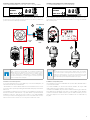
Installation of K275Y011/013 actuator on R296 mixing valve
Use the Connection kit 0296 included in the actuator package.
Before installing the K275Y011/013 actuator on the R296 mixing valve, make sure
the valve is in by-pass position (milling in OFF position) and the actuator is in closing
position.
With the body valve on the left and the by-pass T-shaped fitting on the right, the DIP1
must be positioned on OFF (1a).
With the body valve on the right and the by-pass T-shaped fitting on the left, the DIP1
must be positioned on ON (1b).
Installazione attuatore K275Y011/013 su valvola miscelatrice R296
Utilizzare il Connection kit 0296 contenuto nella confezione dell’attuatore.
Prima di installare l’attuatore K275Y011/013 sulla valvola miscelatrice R296, vericare
che la valvola sia in posizione di by-pass (fresatura in posizione OFF) e l’attuatore in
posizione di chiusura.
Con il corpo valvola a sinistra e il raccordo a T di by-pass a destra, il DIP1 deve essere
posizionato su OFF (1a).
Con il corpo valvola a destra e il raccordo a T di by-pass a sinistra, il DIP1 deve essere
posizionato su ON (1b).
234 5
SYSTEM SIDE
BOILER ROOM
SIDE
SYSTEM SIDE
BOILER ROOM
SIDE
SYSTEM SIDE
BOILER ROOM
SIDE
SYSTEM SIDE
BOILER ROOM
SIDE
1b
ON
OFF
SYSTEM SIDE
BOILER ROOM
SIDE
SYSTEM SIDE
BOILER ROOM
SIDE
SYSTEM SIDE
BOILER ROOM
SIDE
SYSTEM SIDE
BOILER ROOM
SIDE
1a
ON
OFF
Nero: apertura
Blu: neutro
Marrone: chiusura
Black: opening
Blue: neutral
Brown: closing
Nero: chiusura
Blu: neutro
Marrone: apertura
Black: closing
Blue: neutral
Brown: opening
K275Y011 K275Y011
K275Y013 K275Y013
Connection kit
GIACOMINI
CODE: 0296
Connection kit
GIACOMINI
CODE: 0296

8
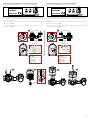
FUNZIONAMENTO CIRCOLATORE WILO PARA 25/7 WILO PARA 25/7 CIRCULATOR OPERATION
Pressione dierenziale variabile Δp-v (I, II, III)
Consigliata in caso di sistemi di riscaldamento a doppia mandata con radiatori, per
la riduzione dei rumori di usso sulle valvole termostatiche. Il circolatore dimezza la
prevalenza in caso di riduzione della portata nella rete di condutture. Si risparmia
energia elettrica grazie all’adattamento della prevalenza in base alla portata necessaria
e a velocità di usso ridotte. Tre curve caratteristiche predenite (I, II, III) tra cui scegliere.
0
0
1
2
0
20
40
60
3
4
5
6
7
8
∆p-v (variabile)
0
10
20
30
40
50
60
70
80
0,5 1,0 1,5 2,0 3,0 4,03,52,5
0 0,5 1,0 1,5 2,0 3,0 4,03,52,5
Q [m3/h]
Q [m3/h]
P1 [W]
H [m]
H [kPa]
III
II
I
∆p-v
max.
max.
III II I
0
0
1
2
0
20
40
60
3
4
5
6
7
8
∆p-c (costante)
0
10
20
30
40
50
60
70
80
0,5 1,0 1,5 2,0 3,0 4,03,52,5
0 0,5 1,0 1,5 2,0 3,0 4,03,52,5
Q [m3/h]
Q [m3/h]
P1 [W] H [m]
H [kPa]
III
II
I
∆p-c
max.
max.
III
II
I
0
0
2
0
20
40
60
4
6
8
10
Velocità costante (I, II, III)
0
10
20
30
40
50
60
70
80
0,5 1,0 1,5 2,0 3,0 4,03,52,5
0 0,5 1,0 1,5 2,0 3,0 4,03,52,5
Q [m3/h]
Q [m3/h]
P1 [W] H [m]
H [kPa]
III
II
I
III
II
I
0
0
1
2
0
20
40
60
3
4
5
6
7
8
∆p-v (variabile)
0
10
20
30
40
50
60
70
80
0,5 1,0 1,5 2,0 3,0 4,03,52,5
0 0,5 1,0 1,5 2,0 3,0 4,03,52,5
Q [m3/h]
Q [m3/h]
P1 [W]
H [m]
H [kPa]
III
II
I
∆p-v
max.
max.
III II I
0
0
1
2
0
20
40
60
3
4
5
6
7
8
∆p-c (costante)
0
10
20
30
40
50
60
70
80
0,5 1,0 1,5 2,0 3,0 4,03,52,5
0 0,5 1,0 1,5 2,0 3,0 4,03,52,5
Q [m3/h]
Q [m3/h]
P1 [W] H [m]
H [kPa]
III
II
I
∆p-c
max.
max.
III
II
I
0
0
2
0
20
40
60
4
6
8
10
Velocità costante (I, II, III)
0
10
20
30
40
50
60
70
80
0,5 1,0 1,5 2,0 3,0 4,03,52,5
0 0,5 1,0 1,5 2,0 3,0 4,03,52,5
Q [m3/h]
Q [m3/h]
P1 [W] H [m]
H [kPa]
III
II
I
III
II
I
Variable dierential pressure Δp-v (I, II, III)
Recommended for two-pipe heating systems with radiators to reduce the flow noise at
thermostatic valves. The pump reduces the delivery head to half in the case of decreasing
volume flow in the pipe network. Electrical energy saving by adjusting the delivery head
to the volume flow requirement and lower flow rates.
There are three pre-defined pump curves (I, II, III) to choose from.
Pressione dierenziale costante Δp-c (I, II, III)
Raccomandazione in caso di panelli radianti o tubazioni di grandi dimensioni e per
tutte le applicazioni che non presentano curve caratteristiche dell’impianto variabili,
(come ad es. pompe cariche bollitori) e impianti di riscaldamento a singola mandata
con radiatori. La regolazione mantiene la prevalenza impostata indipendentemente
dalla portata convogliata. Tre curve caratteristiche predenite (I, II, III) tra cui scegliere.
0
0
1
2
0
20
40
60
3
4
5
6
7
8
∆p-v (variabile)
0
10
20
30
40
50
60
70
80
0,5 1,0 1,5 2,0 3,0 4,03,52,5
0 0,5 1,0 1,5 2,0 3,0 4,03,52,5
Q [m3/h]
Q [m3/h]
P1 [W] H [m]
H [kPa]
III
II
I
∆p-v
max.
max.
III II I
0
0
1
2
0
20
40
60
3
4
5
6
7
8
∆p-c (costante)
0
10
20
30
40
50
60
70
80
0,5 1,0 1,5 2,0 3,0 4,03,52,5
0 0,5 1,0 1,5 2,0 3,0 4,03,52,5
Q [m3/h]
Q [m3/h]
P1 [W] H [m]
H [kPa]
III
II
I
∆p-c
max.
max.
III
II
I
0
0
2
0
20
40
60
4
6
8
10
Velocità costante (I, II, III)
0
10
20
30
40
50
60
70
80
0,5 1,0 1,5 2,0 3,0 4,03,52,5
0 0,5 1,0 1,5 2,0 3,0 4,03,52,5
Q [m3/h]
Q [m3/h]
P1 [W] H [m]
H [kPa]
III
II
I
III
II
I
0
0
1
2
0
20
40
60
3
4
5
6
7
8
∆p-v (variabile)
0
10
20
30
40
50
60
70
80
0,5 1,0 1,5 2,0 3,0 4,03,52,5
0 0,5 1,0 1,5 2,0 3,0 4,03,52,5
Q [m3/h]
Q [m3/h]
P1 [W] H [m]
H [kPa]
III
II
I
∆p-v
max.
max.
III II I
0
0
1
2
0
20
40
60
3
4
5
6
7
8
∆p-c (costante)
0
10
20
30
40
50
60
70
80
0,5 1,0 1,5 2,0 3,0 4,03,52,5
0 0,5 1,0 1,5 2,0 3,0 4,03,52,5
Q [m3/h]
Q [m3/h]
P1 [W] H [m]
H [kPa]
III
II
I
∆p-c
max.
max.
III
II
I
0
0
2
0
20
40
60
4
6
8
10
Velocità costante (I, II, III)
0
10
20
30
40
50
60
70
80
0,5 1,0 1,5 2,0 3,0 4,03,52,5
0 0,5 1,0 1,5 2,0 3,0 4,03,52,5
Q [m3/h]
Q [m3/h]
P1 [W] H [m]
H [kPa]
III
II
I
III
II
I
Constant dierential pressure Δp-c (I, II, III)
Recommended for underfloor heating for large-sized pipes or all applications without a
variable pipe network curve (e.g. storage charge pumps), as well as single-pipe heating
systems with radiators.
The control keeps the set delivery head constant irrespective of the pumped volume flow.
There are three pre-defined pump curves (I, II, III) to choose from.
Numero di giri costante (I, II, III) [IMPOSTAZIONE DI FABBRICA]
Consigliata per gli impianti con resistenza stabile che richiedono una portata costante. Il
circolatore funziona in tre stadi corrispondenti a numeri di giri ssi preimpostati (I, II, III).
0
0
1
2
0
20
40
60
3
4
5
6
7
8
∆p-v (variabile)
0
10
20
30
40
50
60
70
80
0,5 1,0 1,5 2,0 3,0 4,03,52,5
0 0,5 1,0 1,5 2,0 3,0 4,03,52,5
Q [m3/h]
Q [m3/h]
P1 [W] H [m]
H [kPa]
III
II
I
∆p-v
max.
max.
III II I
0
0
1
2
0
20
40
60
3
4
5
6
7
8
∆p-c (costante)
0
10
20
30
40
50
60
70
80
0,5 1,0 1,5 2,0 3,0 4,03,52,5
0 0,5 1,0 1,5 2,0 3,0 4,03,52,5
Q [m3/h]
Q [m3/h]
P1 [W] H [m]
H [kPa]
III
II
I
∆p-c
max.
max.
III
II
I
0
0
2
0
20
40
60
4
6
8
10
Velocità costante (I, II, III)
0
10
20
30
40
50
60
70
80
0,5 1,0 1,5 2,0 3,0 4,03,52,5
0 0,5 1,0 1,5 2,0 3,0 4,03,52,5
Q [m3/h]
Q [m3/h]
P1 [W] H [m]
H [kPa]
III
II
I
III
II
I
0
0
1
2
0
20
40
60
3
4
5
6
7
8
∆p-v (variabile)
0
10
20
30
40
50
60
70
80
0,5 1,0 1,5 2,0 3,0 4,03,52,5
0 0,5 1,0 1,5 2,0 3,0 4,03,52,5
Q [m3/h]
Q [m3/h]
P1 [W] H [m]
H [kPa]
III
II
I
∆p-v
max.
max.
III II I
0
0
1
2
0
20
40
60
3
4
5
6
7
8
∆p-c (costante)
0
10
20
30
40
50
60
70
80
0,5 1,0 1,5 2,0 3,0 4,03,52,5
0 0,5 1,0 1,5 2,0 3,0 4,03,52,5
Q [m3/h]
Q [m3/h]
P1 [W] H [m]
H [kPa]
III
II
I
∆p-c
max.
max.
III
II
I
0
0
2
0
20
40
60
4
6
8
10
Velocità costante (I, II, III)
0
10
20
30
40
50
60
70
80
0,5 1,0 1,5 2,0 3,0 4,03,52,5
0 0,5 1,0 1,5 2,0 3,0 4,03,52,5
Q [m3/h]
Q [m3/h]
P1 [W] H [m]
H [kPa]
III
II
I
III
II
I
Constant speed (I, II, III) [FACTORY SETTING]
Recommended for systems with fixed system resistance requiring a constant volume
flow. The pump runs in three prescribed fixed speed stages (I, II, III).

9
N° Pressioni pulsante
N° of button pressures
Indicatore LED
LED display
Modo di regolazione
Control mode
Curva caratteristica
Circulator curve
1Numero di giri costante
Constant speed II
2Numero di giri costante
Constant speed I
3Pressione differenziale variabile Δp-v
Variable differential pressure Δp-v III
4Pressione differenziale variabile Δp-v
Variable differential pressure Δp-v II
5Pressione differenziale variabile Δp-v
Variable differential pressure Δp-v I
6Pressione differenziale costante Δp-c
Constant differential pressure Δp-c III
7Pressione differenziale costante Δp-c
Constant differential pressure Δp-c II
8Pressione differenziale costante Δp-c
Constant differential pressure Δp-c I
9
(IMPOSTAZIONE DI FABBRICA)
(FACTORY SETTING)
Numero di giri costante
Constant speed III
Impostare il modo di funzionameto
La selezione LED del modo di regolazione e delle curve caratteristiche
corrispondenti si svolge in senso orario.
• Premere il tasto di comando brevemente (circa 1 secondo).
I LED mostrano di volta in volta modo di regolazione e curve
caratteristiche impostati.
Di seguito vengono illustrate le possibili impostazioni (ad esempio:
numero di giri costante/curva caratteristica III):
Setting the control mode
The LED selection of control modes and corresponding pump curves
takes place in clockwise succession.
• Press the operating button briefly (approx. 1 second).
LEDs display the set control mode and pump curve.
The following shows the various possible settings (for example:
constant speed / characteristic curve III):

10
Sato aria
• Riempire e satare correttamente l’impianto.
Se ciò non avviene:
• Attivare la funzione di sato del circolatore premendo per 3
secondi il tasto di comando, quindi lasciare.
La funzione di sato del circolatore si avvia e dura 10 minuti.
Le due serie di LED superiori e inferiori lampeggiano
alternativamente a distanza di 1 secondo.
• Per interrompere, premere il tasto di comando per 3 secondi.
Dopo lo sato l’indicatore LED mostra i valori impostati del
circolatore.
Air venting
• Fill and vent the system correctly.
If the pump does not vent automatically:
• Activate the pump venting function via the operating button:
press and hold for 3 seconds, then release.
The pump venting function is initiated and lasts 10 minutes.
The top and bottom LED rows flash in turn at 1 second
intervals.
• To cancel, press and hold the operating button for 3 seconds.
After venting, the LED display shows the previously set values
of the pump.
Segnalazioni di blocco
• Il LED di anomalia segnala un guasto.
• Il circolatore si ferma (a seconda del guasto), ed eettua dei tentativi ciclici di riavvio.
LED Guasti
Faults
Cause
Causes
Rimedi
Remedy
Si illumina con luce rossa
Lights up red
Blocco
Blocking
Rotore bloccato
Rotor blocked Attivare il riavvio manuale o
contattare il supporto tecnico
Activate manual restart or
acontact customer service
Contatto/avvolgimento
Contacting/winding
Avvolgimento difettoso
Winding defective
Lampeggia con luce rossa
Flashing red
Sotto/sovratensione
Under/overvoltage
Tensione di alimentazione lato alimentazione troppo bassa/alta
Power supply too low/high on mains side
Controllare la tensione di rete e le condizioni
d’impiego o contattare il supporto tecnico
Check mains voltage and operating conditions,
and request customer service
Temperatura eccessiva del modulo
Excessive module temperature
Interno del modulo troppo caldo
Module interior too warm
Cortocircuito
Short-circuit
Corrente del motore troppo alta
Motor current too high
Lampeggia con luce rossa/verde
Flashes red/ green
Funzionamento turbina
Generator operation
Il sistema idraulico del circolatore viene alimentato,
ma il circolatore non ha tensione di rete
Water is flowing through the pump hydraulics,
but there is no mains voltage at the pump
Vericare la tensione di rete,
la portata/pressione dell’acqua
nonché le condizioni ambientali
Check the mains voltage,
water quantity/pressure
and the ambient conditions
Funzionamento a secco
Dry run
Aria nel circolatore
Air in the pump
Sovraccarico
Overload
Il motore gira con difcoltà. Il circolatore sta funzionando non
conformemente alle speciche (ad es. temperatura del modulo elevata).
Il numero di giri è più basso rispetto al funzionamento normale
Sluggish motor, pump is operated outside of its specications (e.g. high module
temperature). The speed is lower than during normal operation
Fault signals
• The fault signal LED indicates a fault.
• The pump switches off (depending on the fault) and attempts a cyclical restart.

11
Dimensioni Dimensions
L
F
E
HC
D
G
I
B B
A A
Ø10
Ø10
Codice - Code A x B C [mm] D [mm] E [mm] F [mm] G [mm] H [mm] I [mm] L [mm]
R586RY102 G 1-1/2”M
x
G 1”F
125 250 180 430 100 65 165 160
R586RY112
Riferimenti normativi - Standards reference
• PED 2014/68/EU, par. 4.3
• LVD 2014/35/EU
• EMC 2014/30/EU
• ErP 2009/125/EU
• RoHS 2011/65/EU
• Conformità CE e UKCA: solo per versioni con circolatore
Compliance CE and UKCA: only for versions with circulator
Imported by GIACOMINI U.K.
Unit 2, Goodrich Close, Westerleigh Business Park,
Yate, South Gloucestershire, BS37 5YT.
suppor[email protected] 01454311012
La pagina sta caricando ...
La pagina sta caricando ...
La pagina sta caricando ...
La pagina sta caricando ...
La pagina sta caricando ...
La pagina sta caricando ...
La pagina sta caricando ...
La pagina sta caricando ...
La pagina sta caricando ...
La pagina sta caricando ...
La pagina sta caricando ...
La pagina sta caricando ...
La pagina sta caricando ...
La pagina sta caricando ...
La pagina sta caricando ...
La pagina sta caricando ...
La pagina sta caricando ...
La pagina sta caricando ...
La pagina sta caricando ...
La pagina sta caricando ...
La pagina sta caricando ...
-
 1
1
-
 2
2
-
 3
3
-
 4
4
-
 5
5
-
 6
6
-
 7
7
-
 8
8
-
 9
9
-
 10
10
-
 11
11
-
 12
12
-
 13
13
-
 14
14
-
 15
15
-
 16
16
-
 17
17
-
 18
18
-
 19
19
-
 20
20
-
 21
21
-
 22
22
-
 23
23
-
 24
24
-
 25
25
-
 26
26
-
 27
27
-
 28
28
-
 29
29
-
 30
30
-
 31
31
-
 32
32
-
 33
33
-
 34
34
-
 35
35
-
 36
36
-
 37
37
-
 38
38
-
 39
39
-
 40
40
-
 41
41


in altre lingue
Documenti correlati
-
Giacomini P225E Istruzioni per l'uso
-
-
-
-
-
-
-
-
-
Altri documenti
-
IVAR MULTIMIX-C Manuale utente
-
Immergas 3.033217 Manuale utente
-
Eiki EK-612XA Manuale utente
-
 Olimpia Splendid Sherpa Manuale del proprietario
-
Caleffi 519 series Manuale utente
-
 Kaysun 2-Zone Kit Manuale utente
-
 PIETRO FIORENTINI Terval/A Manuale del proprietario
-
Eiki EK-623UW Manuale utente
-
NORD Drivesystems Dust explosion protection Istruzioni per l'uso
-
NEC NP4001 Manuale del proprietario


