IT
Foglio istruzioni
ed avvertenze
IE
Instruction and
warning book
COD. 3.033217
KIT RICIRCOLO SANITARIO
CON CIRCOLATORE
MAGIS HERCULES PRO MINI
MAGIS HERCULES PRO MINI
DHW RECIRCULATION KIT
WITH CIRCULATOR
STD.010672/000

2
IT IE
IL PRESENTE FOGLIO È DA LASCIARE ALL'UTENTE
ABBINATO AL LIBRETTO ISTRUZIONI DI CALDAIA
Avvertenze generali.
Tutti i prodotti Immergas sono protetti con idoneo imballaggio
da trasporto. Il materiale deve essere immagazzinato in ambienti
asciutti ed al riparo dalle intemperie.Il presente foglio istruzioni
contiene informazioni tecniche relative all’installazione del kit
Immergas. Per quanto concerne le altre tematiche correlate
all’installazione del kit stesso (a titolo esemplicativo: sicurezza
sui luoghi di lavoro, salvaguardia dell’ambiente, prevenzioni degli
infortuni), è necessario rispettare i dettami della normativa vigente
ed i principi della buona tecnica.L’installazione o il montaggio
improprio dell’apparecchio e/o dei componenti, accessori, kit e
dispositivi Immergas potrebbe dare luogo a problematiche non
prevedibili a priori nei confronti di persone, animali, cose. Leggere
attentamente le istruzioni a corredo del prodotto per una corretta
installazione dello stesso.L'installazione e la manutenzione devono
essere eettuate in ottemperanza alle normative vigenti, secondo le
istruzioni del costruttore e da parte di personale abilitato nonché
professionalmente qualicato, intendendo per tale quello avente
specica competenza tecnica nel settore degli impianti, come
previsto dalla Legge.
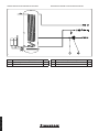
Installazione
- Togliere tensione all'apparecchio disalimentando l'interruttore
a monte dell’apparecchio.
- Accertarsi che il rubinetto ingresso acqua fredda (12) sia
chiuso e scaricare parzialmente il contenuto dell'unità bollitore
agendo sull’apposito rubinetto di svuotamento (vedi libretto
istruzioni).
- Per eettuare questa operazione aprire un qualsiasi rubinetto
dell’acqua calda dell’impianto sanitario per permettere l’entrata
dell’aria nell'unità bollitore.
- Eettuare il collegamento del kit come rappresentato in Fig.
2
N.B.: la valvola di ritegno (1) deve essere premontata unendo i
componenti (1a) e (1b) con loctite/teon o materiale con ana-
loghe caratteristiche e deve essere montata nel corretto senso,
come indicato nello schema idraulico (Fig. 3).
N.B.: prestare attenzione al collegamento della pompa che
deve avere il senso di circolazione dell'acqua uguale alla freccia
rappresentata in Fig. 2.
N.B.: posizionare la sonda ricircolo a monte del circolatore
come indicato in Fig. 2.
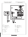
- Connettere il circolatore (5) come indicato nello schema elet-
trico (Fig. 4) e rappresentato nello schema percorso cablaggi
(Fig. 5). Il controllo del circolatore avviene tramite il Kit due
relè da congurare come indicato dal libretto di istruzione
dell'apparecchio.
- Connettere la sonda ricircolo (9) come indicato nello schema
elettrico (Fig. 4) e rappresentato nello schema percorso
cablaggi (Fig. 5)
- Accertarsi di aver chiuso il rubinetto di svuotamento unità
bollitore.
THIS SHEET MUST BE LEFT WITH THE USER
ALONG WITH THE BOILER INSTRUCTION BOOK
General warnings.
All Immergas products are protected with suitable transport
packaging.
e material must be stored in dry environments and protected
against weathering.
This instruction manual provides technical information for
installing the Immergas kit. As for the other issues related to kit
installation (e.g. safety in the work site, environment protection,
injury prevention), it is necessary to comply with the provisions
specied in the regulations in force and principles of good practice.
Improper installation or assembly of the Immergas appliance and/
or components, accessories, kit and devices can cause unexpected
problems to people, animals and objects. Read the instructions
provided with the product carefully to ensure a proper installation.
Installation and maintenance must be performed in compliance
with the regulations in force, according to the manufacturer's
instructions and by professionally qualied sta, intending sta
with specic technical skills in the plant sector, as envisioned by
the Law.
Installation
- Cut power to the appliance by disconnecting the switch up-
stream from the device.
- Make sure that the cold water inlet cock (12) is closed and
partially drain the contents of the storage tank unit acting on
the relevant drain valve (see instructions booklet).
- To perform this operation open any hot water tap of the do-
mestic hot water system to let air into the storage tank unit.
- Connect the kit as shown in the Fig. 2
N.B.: Check valve (1) must be preassembled by joining the com-
ponents (1a) and (1b) with loctite/teon or material with similar
characteristics and must be assembled in the correct direction,
as indicated in the hydraulic diagram (Fig. 3).
N.B.: pay attention to the connection of the pump whose water
circulation direction must be the same as the arrow shown in
the Fig. 2.
N.B.: position the recirculation probe upstream of the pump as
indicated in Fig. 2.
- Connect the circulator (5) as indicated in the wiring diagram
(Fig. 4) and represented in the cable path diagram (Fig. 5). e
circulator is controlled using the two relay kit to be congured
as indicated in the appliance instruction booklet.
- Connect the recirculation probe (9) as indicated in the wiring
diagram (Fig. 4) and represented in the cable path diagram
(Fig. 5)
- Make sure to have closed the storage tank unit draining valve.
STD.010672/000

3
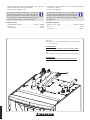
12
Legenda:
12 - Rubinetto entrata acqua fredda (presente nel gruppo
allacciamento)
ATTENZIONE:
questo circolatore è indicato solo per l'acqua potabile
Key:
12 - Cold water inlet valve (present in connection unit)
ATTENTION:
this circulator is indicated for drinking water only
- Riaprire il rubinetto entrata acqua fredda (12) per portarla
alle normali condizioni di funzionamento.
- Ridare tensione all’apparecchio.
Per evitare condizioni di stallo, in caso di instal-
lazione del kit ricircolo con valvola miscelatrice
termostatica all'interno del kit solare, assicurarsi di
aver congurato la temperatura dell'acqua miscelata
ad un set superiore del set sanitario impostato.
DATI TECNICI:
- Alimentazione elettrica: ................................. 230 Vac / 50 HZ
- Potenza: ............................................................................... 45 W
- Assorbimento: ..................................................................0,24 A
- Reopen the cold water inlet cock (12) to bring it to normal
operation conditions.
- Re-power the appliance.
To avoid stall conditions, in case of installation of
the recirculation kit with thermostatic mixing valve
inside the solar kit, make sure you have congured
the mixed water temperature at a higher setting than
the DHW set.
TECHNICAL DATA:
- Electric power supply: ....................................230 Vac / 50 HZ
- Power: ..................................................................................45 W
- Absorption: ....................................................................... 0.24 A
1
STD.010672/000

4
1
2
2
3
4
4
5
6
8
9
10
7
11
1a
1b
2
Composizione kit.
Rif Descrizione componenti kit Qtà
1 Valvola ritegno G 3/4" F - G 3/4" M 1
2 Guarnizioni 24x16x2 mm 2
3 Tubo allacciamento ricircolo 1
4 Guarnizioni 29x20x2 mm 2
5 Circolatore 1
6 Raccordo tubo allacciamento G 3/4'' 1
7 Tubo allacciamento 1
8 Dado G 1" 1
9 Sonda ricircolo 1
10 Guarnizioni 18,5x11,5x2 mm 1
11 Tapp o 1
Kit composition.
Ref Kit components description Qty
1 Check valve G/3/4" F - G/3/4" M 1
2 Gaskets 24x16x2 mm 2
3 Recirculation connection pipe 1
4 Gaskets 29x20x2 mm 2
5 Pump 1
6 Connection pipe tting G 3/4'' 1
7Connection pipe 1
8 G 1" nut 1
9 Recirculation Probe 1
10 Gaskets 18,5x11,5x2 mm 1
11 Cap 1
STD.010672/000

5
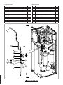
3
SCHEMA IDRAULICO KIT RICIRCOLO SANITARIO HYDRAULIC DIAGRAM D.H.W. RECIRCULATION KIT
Rif Descrizione componenti kit Qtà
1 Valvola ritegno G 3/4" F - G 3/4" M 1
5 Circolatore 1
Ref Kit components description Qty
1 Check valve G/3/4" F - G/3/4" M 1
5 Pump 1
STD.010672/000

6
1
2
4
Legenda:
A13 - Scheda di supervisione
B32 - Sonda ricircolo sanitario
K70-A,B- Relè multifunzione
M4 - Circolatore ricircolo sanitario
1 - Cruscotto
2 - Quadro principale
Legenda colori cablaggio:
BK - Nero
BL - Blu
BR - Marrone
G - Verde
G/Y - Giallo/Verde
R - Rosso
Key:
A13 - Supervision board
B32 - D.H.W recirculation probe
K70-A,B- Multifunction relay
M4 - D.H.W. recirculation pump
1 - Control panel
2 - Main panel
Color codes wiring:
BK - Black
BL - Blue
BR - Brown
G - Green
G/Y - Green/Yellow
R - Red
SCHEMA ELETTRICO CONNESSIONI
KIT RICIRCOLO SANITARIO
WIRING DIAGRAM CONNECTIONS D.H.W.
RECIRCULATION KIT
STD.010672/000

7
B32
M4
2
1
21
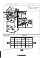
0 200 400 600 800 1000 1200
X1
Y1 Y2
20
40
10
30
50
0
20
40
10
30
50
0
1
2
Prevalenza circolatore. Circulator head.
6
SCHEMA PERCORSO CAVI CONNESSIONI
KIT RICIRCOLO SANITARIO
CABLE ROUTING DIAGRAM CONNECTIONS D.H.W.
RECIRCULATION KIT
5
X1 = Portata (l/h)
Y1 = Prevalenza (kPa)
Y2 = Potenza assorbita dal circolatore (W)
1 = Potenza assorbita dal circolatore
2 = Prevalenza disponibile all'impianto
X1 = Flow rate (l/h)
Y1 = Head (kPa)
Y2 = Pump absorbed power (W)
1 = Pump absorbed power
2 = Total head available to the system
Legenda:
1 - Connessione sonda ricircolo (B32)
2 - Connessione circolatore (M4)
Key:
1 - Recirculation Probe connection (B32)
2 - Circulator pump connection (M4)
STD.010672/000

Il libretto istruzioni è realizzato in carta ecologica. Cod. 1.048422 - rev. ST.007253/000 -06/23
Nel corso della vita utile dei prodotti, le prestazioni sono
inuenzate da fattori esterni, come ad es. la durezza dell'acqua
sanitaria, gli agenti atmosferici, le incrostazioni nell'impianto
e così via. I dati dichiarati si riferiscono ai prodotti nuovi e
correttamente installati ed utilizzati, nel rispetto delle norme
vigenti.
N.B.: si raccomanda di fare eseguire una corretta
manutenzione periodica.
During the useful life of the products, performance is aected
by external factors, e.g. the hardness of the DHW, atmospheric
agents, deposits in the system and so on. e data declared
refer to new products that are correctly installed and used with
respect to the Standards in force.
N.B.: correct periodic maintenance is highly recommended.
immergas.com
Per richiedere ulteriori approfondimenti specici, i Professionisti
del settore possono anche avvalersi dell’indirizzo e-mail:
To request further specic details, sector Professionals can also
use the following e-mail address: [email protected]
Immergas S.p.A.
42041 Brescello (RE) - Italy
Tel. 0522.689011
Fax 0522.680617
Il libretto istruzioni è realizzato in carta ecologica
is instruction booklet is madeof ecological paper.
STD.010672/000
-
 1
1
-
 2
2
-
 3
3
-
 4
4
-
 5
5
-
 6
6
-
 7
7
-
 8
8


Documenti correlati
-
Immergas 3.014083 Istruzioni per l'uso
-
Immergas DIMV2 Manuale utente
-
Immergas COD. 3.030908 Istruzioni per l'uso
-
-
Immergas Victrix TT Series Manuale utente
-
Immergas ST.005829 Manuale utente
-
Immergas CODE 3.032258 Istruzioni per l'uso