
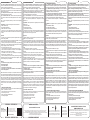
EN: (A) Connection point, (B) Connection slot, (C) Anchorage point.
Fabric: Aluminium alloy.
IT: (A) Punto di connessione, (B) Asola di connessione, (C) Punto di
ancoraggio.
Materiale: Lega di alluminio.
FR: (A) Point de connexion, (B) Boucle de connexion, (C) Point d’an-
crage.
Matière: Alliage d’aluminium.
DE: (A) Verbindungspunkt, (B) Anschlussschlitz, (C) Verankerungs-
punkt.
Material: Aluminiumlegierung.
EN: Class III 864.018 DISCORIG Personal Protection Equipment is:
- an anchorage with several attachment points and the need for a xing
element to attach it to the structure through the hole (C), for simultane-
ous use by up to 6 users;
- one plate for multiple connections with simultaneous connection of
up to 6 users;
• part of a system for protection against impact arising from falling from
heights;
- certied according to EN 795:2012/A and CEN/TS16415:2013/A
standards, and RfU CNB/P/11.114.
IT: Il Dispositivo di Protezione Individuale di III categoria 864.018
DISCORIG (g. 1) è:
- un ancoraggio con più punti di attacco e con la necessità di un
elemento di ssaggio per annetterlo alla struttura mediante il foro (C),
per l’utilizzo contemporaneo no a 6 utilizzatori;
- una piastra per connessioni multiple con collegamento contemporaneo
no a 6 utilizzatori;
- parte di un sistema di protezione e/o prevenzione dall’impatto
derivante da cadute dall’alto;
- certicato in accordo agli standard EN 795:2012/A e CEN/
TS16415:2013/A, e alla RfU CNB/P/11.114.
FR: L’équipement de Protection Individuelle de catégorie III 864.018
DISCORIG (g. 1) est:
- un ancrage muni de plusieurs points d’attache nécessitant un élément
de xation an de le rattacher à la structure grâce au trou (C), conçu
pour l’utilisation simultanée d’un maxiumum de 6 personnes;
- une plaque permettant une connexion multiple pour un maximum de
6 utilisateurs simultanés;
- une partie d’un système de protection et/ou de prévention de l’impact
dérivant d’une chute de hauteur;
- certié conformément aux standards EN 795:2012/A et CEN/
TS16415:2013/A, et à la RfU CNB/P/11.114.
DE: Die persönliche Schutzausrüstung der Kategorie III 864.018
DISCORIG (Abb. 1) ist:
- ein Anker mit mehreren Befestigungspunkten und der Notwendigkeit
eines Befestigungselements um ihn durch das Loch (C) an der Struk-
tur zu befestigen, damit ihn gleichzeitig bis zu 6 Benutzer verwenden
können;
- eine Platte für mehrere Verbindungen mit gleichzeitigem Anschluss
von bis zu 6 Teilnehmern;
- Teil eines Systems zum Schutz und/oder zur Verhinderung von Stür-
zen aus der Höhe;
- zertiziert nach EN 795:2012/A und CEN/TS16415:2013/A und RfU
CNB/P/11.114.
NOMENCLATURE • TERMINOLOGIE
NOMENCLATURE • NOMENCLATURA
DESCRIPTION • DESCRIZIONE
DESCRIPTION • BESCHREIBUNG
2
A
B
C
1
EN 795:2012
CEN/TS 16415:2013
type A
MAX 6 USER
4 5
7
3TEXTILE FRIENDLY!
MADE FOR 4D SYSTEM
A
A
B and C
MINIPALO 4D
817500000KK
MAX 36 kN
AVOID IMPACTS!
C
A
B
C
C
C
A/B
AA
ANCHOR DIAMETER 36mm TO 38mm
ANCHOR MINIMUM STRENGHT 12 kN
A
B/C
A
6
KEEP IN MIND
FORCE COMPOSITION!
MAX 36 kN
ZZV05588 Rev. 0
DISCORIG
KONG s.p.a.
Via XXV Aprile, 4 - (zona industriale)
I - 23804 MONTE MARENZO (LC) - ITALY
Tel +39 0341630506 - Fax +39 0341641550 - [email protected]
864.018
Stáhněte si překlad ve vašem jazyce - Laden Sie die Übersetzung in
Ihrer Sprache herunter - Download the translation in your language
- Bájate la traducción en tu idioma - Télécharger la traduction dans
vostre langue - Scarica la traduzione nella tua lingua - Download
de vertaling in je eigen taal - Pobierz tłumaczenie w twoim języku
- Faça o download da tradução no seu idioma - Скачайте перевод
на ваш язык - 下载您的语言的译文

8 – SPECIFIC INFORMATION
Fig. 3 - Use as a plate for multiple connections - Various system combina-
tions can be created thanks to the versatility of this device, which also allows
the direct connection of other textile devices.
Fig. 4 - Use as an anchor device - Connect this device to the structure via
the anchor point (C) to create an anchor in accordance with EN795:2012 and
CEN/TS 16415:2013 type A.
Fig. 5 - Examples of correct use as a plate - Check that the maximum load
applied to the device is less than 36kN.
Fig. 6 - Calculation of the forces - Take into account the composition of the
forces and check that the maximum load applied to the device is less than
36kN.
Fig. 7 - Wrong and dangerous positioning - The device must be protected
from shocks.
Compatibility – this device was designed to be used combined with:
- eN1891 or EN892 ropes;
- lanyard EN354 and/or EN566;
- eN362 and/or EN12275 connectors;
- when used as an anchor, tubular fasteners with a diameter of between
36mm and 38mm, with a shoulder of at least 48mm in diameter if the fastener
is vertical.
Important:
- use the device only for protection and prevention against falls from a height
and not for lifting materials;
- if the marking of the anchor device is not visible after installation, it must be
marked on a sign to be applied in the immediate vicinity;
- when using this device as part of a fall arrest system, equip yourself with
suitable means (e.g. energy absorbers) that reduce the impact forces created
during the stopping of a fall to a maximum of 6kN
- when the device is used as an anchor:
- It is recommended to mark the date of the last inspection on the device;
- consider the maximum displacement of the device in the load application
condition (up to 360° rotation and 70mm bending);
- the installation must be carried out by competent persons and properly
checked by means of calculations or tests;
- consider the suitability of the structure according to the load (up to 12kN)
transmitted by the device during use and its direction of application, which
varies according to the type of installation.
Warning:
- the device must be properly installed to the fastener to prevent unin-
tentional disconnection;
- the connected devices:
- must not interfere with each other;
- must be free to move and position themselves in the foreseeable di-
rection of load application.
Note: the installer of the anchoring devices, as required for EN 795 devices,
must issue the client with the installation documentation, signed by the same,
which contains at least the following information: address and place of instal-
lation, the name and address of the company that carried out the installation,
the name of the person in charge of the installation, the identication of the
anchoring device, the methods and data relating to the xing, the schematic
installation plan to be shown to users. This documentation must be kept by
the client in order to record the subsequent inspections of the anchorage
device.
9 - PRE AND AFTER USE CHECKS
Prior to and after using, ensure the device is in efcient condition and proper
operation. In particular check whether:
- is t for the purpose for which you wish it to be used;
- there are no signs of cracks,
- it does not bear mechanical deformations,
- the markings are legible.
8 – INFORMAZIONI SPECIFICHE
Fig. 3 – Utilizzo come piastra per connessioni multiple – È possibile creare
varie combinazioni di sistemi grazie alla versatilità di questo dispositivo, che
permette anche il collegamento diretto di altri dispositivi tessili.
Fig. 4 – Utilizzo come dispositivo di ancoraggio – Collegare questo
dispositivo alla struttura tramite il punto di ancoraggio (C) per realizzare un
ancoraggio in accordo alla EN795:2012 e CEN/TS 16415:2013 tipo A.
Fig. 5 – Esempi di corretto utilizzo come piastra - Vericare che il massimo
carico applicato al dispositivo sia inferiore a 36kN.
Fig. 6 – Calcolo delle forze – Tener conto della composizione delle forze e
vericare che il massimo carico applicato al dispositivo sia inferiore a 36kN.
Fig. 7 – Errato e pericoloso posizionamento – Il dispositivo deve essere
protetto da urti.
Compatibilità - Questo dispositivo è stato progettato per essere utilizzato in
abbinamento a:
- funi EN1891 o EN892;
- lanyard EN354 e/o EN566;
- connettori EN362 e/o EN12275;
- quando usato come ancoraggio, elementi di ssaggio tubulari il cui diametro
sia compreso tra 36mm e 38mm, con uno spallamento di diametro 48mm
almeno se l’elemento di ancoraggio è verticale.
Importante:
- utilizzare il dispositivo solo per la protezione e prevenzione contro le cadute
dall’alto e non per sollevare materiali;
- se la marcatura del dispositivo di ancoraggio non è visibile dopo l’installazione,
è necessario riportarla su un cartello da applicare nell’immediata vicinanza;
- quando si utilizza questo dispositivo come parte di un sistema anticaduta,
equipaggiarsi con mezzi idonei (ad es. assorbitori di energia) che riducano le
forze di impatto che si creano durante l’arresto di una caduta ad un massimo
di 6kN
- quando il dispositivo è utilizzato come ancoraggio:
- è raccomandabile marcare sul dispositivo la data dell’ultima ispezione
effettuata;
- considerare il massimo spostamento del dispositivo nella condizione di
applicazione del carico (no a 360° di rotazione e 70mm di essione);
- l’installazione deve essere effettuata da persone competenti e vericata
adeguatamente mediante calcoli o collaudi;
- considerare l’idoneità della struttura in funzione del carico (no a 12kN)
trasmesso dal dispositivo durante l’utilizzo e la relativa direzione di
applicazione, variabile in accordo alla tipologia di installazione;
Attenzione:
- il dispositivo deve essere adeguatamente installato all’elemento di
ssaggio al ne di evitare la disconnessione non intenzionale;
- i dispositivi collegati:
- non devono interferire tra loro;
- devono essere liberi di muoversi e di posizionarsi nella prevedibile
direzione di applicazione del carico.
Nota: l’installatore dei dispositivi di ancoraggio, come previsto per i dispositivi
EN 795, deve rilasciare al committente la documentazione di installazione,
sottoscritta dallo stesso, che contenga almeno le seguenti informazioni:
indirizzo e luogo dell’installazione, il nome ed indirizzo dell’azienda che ha
eseguito l’installazione, il nome della persona incaricata dell’installazione,
l’identicazione del dispositivo di ancoraggio, le modalità e i dati relativi al
ssaggio, il piano schematico di installazione da esporre agli utenti. Tale
documentazione deve essere conservata dal committente per registrare le
successive ispezioni del dispositivo di ancoraggio.
9 - CONTROLLI PRE E POST USO
Prima e dopo l’uso assicurarsi che il dispositivo sia in condizioni efcienti e
funzioni correttamente, in particolare controllare che:
- sia idoneo all’uso cui lo volete destinare;
- non presenti segni di cricche o di usura;
- non abbia subito deformazioni meccaniche;
- le marcature siano leggibili.
8 – INFORMATIONS SPECIFIQUES
Fig. 3 – Utilisation en tant que plaque multi-connexions – Il est possible de
créer plusieurs combinaisons de systèmes grâce à la polyvalence de cet équi-
pement qui permet également la connexion directe à d’autres dispositifs textiles.
Fig. 4 – Utilisation en tant que dispositif d’ancrage – Connectez ce dispositif à
la structure en utilisant le point d’ancrage (C) pour effectuer un ancrage conforme
à la EN795:2012 et CEN/TS 16415:2013 de type A.
Fig. 5 – Exemples de bonne utilisation en tant que plaque - Vériez que la
charge maximale appliquée au dispositif est inférieure à 36kN.
Fig. 6 – Calcul des forces – Tenez compte de la composition de forces et vériez
que la charge maximale appliquée au dispositif est inférieure à 36kN.
Fig. 7 – Positionnement incorrect et dangereux – Le dispositif doit être protégé
des chocs.
Compatibilité - Cet équipement a été conçu pour être utilisé en combinaison
avec:
- les cordes EN1891 ou EN892;
- les cordons EN354 et/ou EN566;
- les mousquetons EN362 et/ou EN12275;
- lorsqu’il est utilisé en tant qu’ancrage, avec les éléments d‘assemblage tubulai-
res dont le diamètre est compris entre 36mm et 38mm, avec un épaulement de
48mm de diamètre si toutefois l’élément d’ancrage est vertical.
Important:
- utilisez l‘équipement uniquement pour la protection et la prévention des chutes
de hauteur, et non pour soulever du matériel;
- si le marquage du dispositif d’ancrage n’est pas visible après l’installation, il est
nécessaire de l‘indiquer sur un panneau à appliquer à proximité du dispositif;
- lorsque le dispositif est utilisé en tant que partie d’un système anti-chute, équi-
pez-vous de matériel adapté (par exemple, des absorbeurs d’énergie) qui rédui-
sent la force d’impact provoquée par l’arrêt de chute à un niveau maximum de
6kN
- lorsque l’équipement est utilisé comme ancrage:
- il est recommandé d’inscrire sur l’équipement la date de la dernière inspection
effectuée;
- tenez compte du déplacement maximal du dispositif en mesure de l’application
de la charge (rotation jusqu’à 360° et 70mm de échissement);
- l’installation doit être effectuée par des personnes compétentes et doit être dû-
ment controlée par le biais de calculs ou de tests;
- tenez compte de la conformité de la structure en fonction de la charge (jusqu’à
12kN) transmise par l’équipement durant l’utilisation ainsi que de la direction rela-
tive où s’exerce la charge, qui varie selon la typologie d’installation.
Attention:
- l’équipement doit être convenablement rattaché à l’élément de xation
pour éviter qu’il ne se déconnecte de manière involontaire;
- les dispositifs connectés:
- ne doivent pas interférer les uns avec les autres;
- doivent être libres de bouger et de se positionner dans la direction atten-
due où s’exerce la charge.
Note: l’installateur des dispositifs d’ancrage, comme prévu pour les équipements
EN 795, doit fournir au commanditaire la documentation concernant l’installation,
souscrite par celui-ci, et contenant au moins les informations suivante: l’adresse
et le lieu de l’installation, le nom et l’adresse de l’entreprise qui a effectué l’in-
stallation, le nom de la personne en charge de l’installation, l’identication du
dispositif d’ancrage, les modalités et les données relatives à la xation, le plan
schématique d’installation à présenter aux utilisateurs. Cette documentation doit
être conservée par le commanditaire an d’enregistrer les prochaines inspections
du dispositif d’ancrage.
9 – CONTROLES AVANT ET APRES UTILISATION
Assurez-vous, avant et après l’utilisation, que l’équipement soit exploité dans des
conditions d’utilisation efcaces et qu’il fonctionne correctement. Contrôlez tout
particulièrement:
- qu’il soit adapté à l’utilisation que vous voulez en faire;
- qu’il ne présente aucun signe de ssure ou d’usure;
- qu’il n’aie pas subi de déformations mécaniques;
- que le marquage soit lisible.
8 – SPEZIFISCHE ANGABEN
Abb. 3 - Verwendung als Platte für mehrere Verbindungen - Dank der Vielsei-
tigkeit dieses Gerätes, das auch den direkten Anschluss anderer Textilgeräte er-
möglicht, können verschiedene Systemkombinationen gebildet werden.
Abb. 4 - Verwendung als Verankerungsvorrichtung - Verbinden Sie diese Vor-
richtung über den Anschlagpunkt (C) mit der Konstruktion, um einen Anker gemäß
EN795:2012 und CEN/TS 16415:2013 Typ A zu erstellen.
Abb. 5 - Beispiele für die korrekte Verwendung als Platte - Überprüfen Sie, ob
die maximale Belastung des Gerätes weniger als 36kN beträgt.
Abb. 6 - Berechnung der Kräfte - Berücksichtigen Sie die Zusammensetzung der
Kräfte und überprüfen Sie, ob die maximale Belastung der Vorrichtung weniger als
36kN beträgt.
Abb. 7 - Falsche und gefährliche Positionierung - Das Gerät muss vor Stößen
geschützt sein.
Kompatibilität – Diese Vorrichtung wurde für folgende kombinierte Anwendung
entworfen:
- Seile nach EN1891 oder EN892;
- Verbindungsmittel EN354 und/oder EN566;
- Steckverbinder nach EN362 und/oder EN12275;
- bei Verwendung als Anker für rohrförmige Verbindungselemente mit einem Durch-
messer zwischen 36 mm und 38 mm, mit einer Schulter von mindestens 48 mm
Durchmesser, wenn das Verbindungselement vertikal ist.
Wichtig:
- verwenden Sie das Gerät nur zum Schutz und Prävention von Stürzen aus der
Höhe und nicht zum Heben von Materialien;
- wenn die Kennzeichnung der Ankervorrichtung nach der Montage nicht sichtbar
ist, muss sie auf einem Schild angebracht werden, das in unmittelbarer Nähe an-
gebracht wird;
- wenn Sie diese Vorrichtung als Teil eines Absturzsicherungssystems verwenden,
statten Sie sich mit geeigneten Mitteln (z.B. Energieabsorbern) aus, die die bei einer
Absturzsicherung entstehenden Aufprallkräfte auf maximal 6kN reduzieren
- wenn die Vorrichtung als Anker verwendet wird:
- es wird empfohlen, das Datum der letzten Inspektion auf dem Gerät zu vermerken;
- die maximale Verschiebung des Gerätes im Lastaufnahmebedingungen (bis zu
360° Drehung und 70mm Biegung) ist zu berücksichtigen;
- die Installation muss von kompetenten Personen durchgeführt und durch Berech-
nungen oder Prüfungen ordnungsgemäß überprüft werden;
- die Eignung der Struktur für die von dem Gerät während des Gebrauchs übertra-
gene Last (bis zu 12kN) und ihre Einsatzrichtung, die je nach Installationsart variiert,
ist zu berücksichtigen.
Achtung:
- das Gerät muss ordnungsgemäß am Befestigungselement installiert sein,
um ein unbeabsichtigtes Trennen zu verhindern;
- die angeschlossenen Geräte:
- dürfen sich nicht gegenseitig stören;
- müssen sich in der vorhersehbaren Richtung der Lastaufbringung frei be-
wegen und positionieren können.
Hinweis: Der Installateur der Verankerungsvorrichtungen, wie es für Vorrichtungen
nach EN 795 erforderlich ist, muss dem Kunden die von ihm unterschriebene Ins-
tallationsdokumentation aushändigen, die mindestens folgende Informationen en-
thält: Adresse und Installationsort, Name und Adresse des Unternehmens, das die
Installation durchgeführt hat, Name des Installationsverantwortlichen, Identizierung
der Verankerungsvorrichtung, Methoden und Daten zur Befestigung, schematischer
Installationsplan, der den Benutzern vorgelegt werden muss. Diese Dokumentation
ist vom Auftraggeber aufzubewahren, um die nachfolgenden Prüfungen der Veran-
kerungsvorrichtung aufzuzeichnen.
9 - KONTROLLEN VOR UND NACH DER ANWENDUNG
Vor und nach der Verwendung ist sicherzustellen, dass sich das Gerät in einem
einwandfreien Zustand bendet und ordnungsgemäß funktioniert. Insbesondere ist
zu überprüfen, dass:
- sie sich für die gewünschte Anwendung eignet;
- es keine Anzeichen von Rissen oder Korrosionsspuren aufweist;
- es keine mechanischen Deformationen erlitten hat;
- die Markierungen lesbar sind.
EN
Master text: ITALIAN Teste de référence: ITALIENNE Referenztext: ITALIENISCH
IT FR DE
NB n° 2008
DOLOMITICERT scarl
Zona Industriale Villanova
30013 Longarone BL – Italy
Download the declarance of conformity at:
Scarica la dichiarazione di conformità a :
Télécharger la déclaration de conformité à:
Laden Sie die Konformitätserlärung herunter zu:
www.kong.it/conformity
Massimo numero di utilizzatori collegati contemporaneamente
Maximum number of users connected at the same time
Nombre maximal d’utilisateurs connectés simultanément
Maximale Anzahl der gleichzeitig verbundenen Benutzer
Conforme allo standard EN 795:2012 e CENT/TS 16415:2013 tipo A: Ancoraggio con necessità di un elemento di ssaggio
Complies with EN 795:2012 and CENT/TS 16415:2013 type A: Anchorage with the need for a fastener
Conforme au standard EN 795:2012 et CENT/TS 16415:2013 de type A: Ancrage nécessitant un élement de xation
Entspricht EN 795:2012 und CENT/TS 16415:2013 Typ A:
Verankerung mit der Notwendigkeit eines Befestigungselements
Massimo carico applicabile
Maximum applicable load:
Charge maximale d’utilisation
Anwendbare Höchstlast:
Caratteristiche dell’elemento di ssaggio: -diametro compreso tra e 36mm 38mm -resistenza minima di 12kN
Characteristics of the fastener: - diameter between 36mm and 38mm - minimum resistance of 12kN
Caractéristiques de l’élément de xation: - diamètre compis entre 36mm et 38mm
- résistance minimale de 12kN
Eigenschaften des Verbindungselements: - Durchmesser zwischen 36mm und 38mm
- Mindestwiderstand von 12kN
CERTIFIED BY • CERTIFICATO DA
CERTIFIÉ PAR • ZERTIFIZIERT VON
MARKING • MARCATURA
MARKIERUNG • MARQUAGE
EN 795:12/A CENT/TS 16415:13/A ANCHOR ELEMENT Ø FROM 36mm TO 38mm
MINIMUM STRENGTH 12kN
MAX 6 MAX 36kN
-
 1
1
-
 2
2


in altre lingue
- English: Kong Discorig User manual
- français: Kong Discorig Manuel utilisateur
- español: Kong Discorig Manual de usuario
- Deutsch: Kong Discorig Benutzerhandbuch


