Robertshaw Ranco ETC Two Stage Electronic Temperature Control Manuale utente
- Tipo
- Manuale utente

INSTALLATION DATA
ETC TWO STAGE ELECTRONIC
TEMPERATURE CONTROL
The Ranco® ETC is a microprocessor
based family of electronic temperature
controls, designed to provide on/o
control for commercial heang, cooling,
air condioning and refrigeraon. The ETC
is equipped with a liquid crystal display
(LCD) that provides a constant readout
of the sensed temperature, and a touch
keypad that allows the user to easily and
accurately select the setpoint temperature,
dierenal and heang/cooling mode
of the operaon. Models are available
that operate on either line voltage
(120/208/240V AC) or low voltage (24V AC).
APPLICATIONS
With its wide temperature setpoint range
and selectable heang or cooling modes,
the ETC can be used for a wide variety of
applicaons including mulple compressor
control, two stage heang, venlaon
control, automac changeover, condenser
fan cycling, space and return air tempera-
ture control, water cooled condensers and
control with alarm funcon.
FEATURES
• Wide setpoint temperature range (-30°F to 220°F) and dierenal
adjustment (1°F to 30°F)
• Simple keypad programming of setpoint temperature, dierenal and
cooling/heang modes
• Two individually programmable stages for heang and/or cooling
• LCD display readout of sensor temperature, control sengs, relay
status and onboard diagnoscs
• LED (Light Eming Diode) backlight to improve visibility of the display
in low light ambient applicaons.
• IP67 rated (water and dust resistant) thermistor-based probe to
remotely monitor temperature
• The sensor probe can be retroed in the eld by the use of factory
installed interconnect
• Remote temperature sensing up to 400 feet
• Two SPDT output relays
• User-selectable Fahrenheit/Celsius scales
• Lockout switch to prevent tampering by unauthorized personnel
• Choice of line voltage and low voltage models available
• Oponal 0 to 10 volt analog output available for remote temperature
indicaon
• An-short Cycle Compressor Delay for cooling applicaons
SPECIFICATIONS
Input Voltage 120 or 208/240V AC (24V AC oponal), 50/60 Hz
Temperature Range -30°F to 220°F
Dierenal Range 1°F to 30°F
Switch Acon SPDT
Sensor Thermistor, 1.94 in. long x 0.25 in. diameter
with 8 . cable, IP67 rated
Power Consumpon 120/208/240V AC: 100 milliamps
24V AC: 2-6V AC
1
Relay Electrical Rangs
NO Contact 120V 208/240V
Full-load amps 9.8 Amps 4.9 Amps
Locked rotor amps 58.8 Amps 29.4 Amps
Resisve amps 9.8 Amps 4.9 Amps
Horsepower 1/2 HP 1/2 HP
NC Contact
Full-load amps 5.8 Amps 2.9 Amps
Locked rotor amps 34.8 Amps 17.4 Amps
Resisve amps 5.8 Amps 2.9 Amps
Horsepower 1/4 HP 1/4 HP
Pilot Duty: 125 VA at 120/208/240 VAC
Control Ambient Temperature
Operang -20°F to 140°F (-29°C to 60°C)
Storage -40°F to 176°F (-40°C to 80°C)
Ambient Humidity 0 to 95%, RH, Non-condensing
0 to 10V Output Impedance 1 K
Enclosure NEMA 1, Plasc
Agency Approvals UL Listed, File E94419, Guide XAPX
CSA Cered, File LR68340, Class 4813 02
ETC ORDERING INFORMATION
Uni-Line OEM Input No. of 0 - 10 V
Numbers Numbers Voltage Stages Output
ETC-211000-000 ETC-211020-000 120/240 2 No
ETC-211100-000 ETC-211120-000 120/240 2 Yes
ETC-212000-000 ETC-212020-000 24 2 No
ETC-212100-000 ETC-212120-000 24 2 Yes
OPERATION
Liquid Crystal Display (LCD)
The LCD display provides a constant readout of the sensor temperature
and indicates if either of the two output relays is energized. When the
S1 annunciator is constantly illuminated during operaon, the Stage 1
relay is energized. Likewise, when the S2 annunciator is constantly
illuminated during operaon, the Stage 2 relay is energized. The display
is also used with the keypad to allow the user to adjust the setpoint
temperatures, dierenals and heang/cooling modes for each stage.
Backlight
When any mode key is pressed, the backlight is acvated and the ETC is
in control mode. Press the SET key to begin program mode.
Control Setup
The temperature setpoint refers to the temperature at which the
normally open (NO) contacts of the output relay will open. Determine
the loads to be controlled and the operang modes required for each
stage, cooling or heang.
•
When the cooling mode is chosen, the dierenal is above the setpoint.
The relay will de-energize as the temperature falls to the setpoint.
• An-short Cycle Compressor Delay for cooling. Aer a relay
de-energizes, the ETC will prevent the relay from turning on unl a
congurable me has occurred to protect compressor.
•
When the heang mode is chosen, the dierenal is below the setpoint.
The relay will de-energize as the temperature rises to the setpoint.
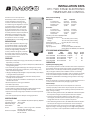
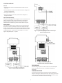
The ETC two stage control can be set up for two stages of heang, two
stages of cooling or one stage cooling plus one stage heang. Refer to
Figures 1, 2 and 3 for a visual representaons of dierent control setups.

2
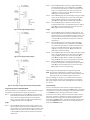
Programming Steps and Display Mode
The ETC two stage can be programmed in seven simple steps using the
LCD display and the three keys on the face of the control.
Step 1 To start programming, press the SET key once to access the
Fahrenheit/Celsius mode. The display will show the current
status, either F for degrees Fahrenheit or C for degrees
Celsius. Then press either the up Ç or down È arrow key
to toggle between the F or C designaon.
Stage 1
Step 2 Press the SET key again to access the stage 1 setpoint. The
LCD will display the current setpoint and the S1 annunciator
will be blinking on and o to indicate that the control is in the
setpoint mode. Then press either the up Ç key to increase
or the down È key to decrease the setpoint to the desired
temperature.
Figure 3: One Stage Cooling and One Stage Heang Example
Figure 2: Two Stage Cooling Example
Figure 1: Two Stage Heang Example
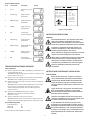
Lockout Switch
The ETC is provided with a lockout switch to prevent tampering by
unauthorized personnel. When placed in the LOCK posion, the keypad
is disabled and no changes to the sengs can be made. When placed
in the UNLOCK posion, the keypad will funcon normally.
To access the lockout switch, disconnect the power supply and open
the control. The switch is located on the inside cover about 2 inches
above the boom. (see Figure 4). To disable the keypad, slide the
switch to the le LOCK posion. To enable the keypad, slide the switch
to the right UNLOCK posion. All ETC controls are shipped with this
switch in the UNLOCK posion.
Step 3 Press the SET key again to access the stage 1 dierenal.
The LCD will display the current dierenal and the DIF 1
annunciator will be blinking on and o to indicate that the
control is in the dierenal mode. Then press either the
up Ç key to increase or the down È key to decrease the
dierenal to the desired seng.
Step 4 Press the SET key again to access the stage 1 cooling or heang
mode. The LCD will display the current mode, either C1 for
cooling or H1 for heang. Then press either the up Ç or
down È key to toggle between the C1 or H1 designaon.
Step 5 Press the SET key again to access the An-short Cycle
Compressor Delay when in Cooling Mode. Press the up Ç or
down È keys to set the delay from 1 to 20 minutes. Press
SET key again to nish the programming.
Stage 2
Step 6 Press the SET key again to access the stage 2 setpoint. The
LCD will display the current setpoint and the S2 annunciator
will be blinking on and o to indicate that the control is in the
setpoint mode. Then press either the up Ç key to increase
or the down È key to decrease the setpoint to the desired
temperature.
Step 7 Press the SET key again to access the stage 2 dierenal.
The LCD will display the current dierenal and the DIF 2
annunciator will be blinking on and o to indicate that the
control is in the dierenal mode. Then press either the
up Ç key to increase or the down È key to decrease the
dierenal to the desired seng.
Step 8 Press the SET key again to access the stage 2 cooling or heang
mode. The LCD will display the current mode, either C2 for
cooling or H2 for heang. Then press either the up Ç or
down È key to toggle between the C2 or H2 designaon.
Press the SET key once more and programming is complete.
Step 9 Press the SET key again to access the An-short Cycle
Compressor Delay when in Cooling Mode. Press the up Ç or
down È keys to set the delay from 1 to 20 minutes. Press
SET key again to nish the programming.
Refer to Page 3 for an illustrated guide to programming the ETC.
NOTE: The ETC will automacally end programming if no keys are
depressed for a period of thirty seconds. Any sengs that have
been input to the control will be accepted at that point.
All control sengs are retained in non-volale memory if power to
ETC is interrupted for any reason. Re-programming is not necessary
aer power outages or disconnects unless dierent control sengs
are required.

3
INSTALLATION INSTRUCTIONS
WARNING
Electrical Shock Hazard - Turn o power at the main
power source before installing the ETC control.
DO NOT restore electrical power to the unit unl the
ETC control is properly installed and cover assembled.
Fire Hazard - DO NOT locate the ETC control in an
explosive atmosphere as a re could result due to
possible spark generaon in the control.
All ETC Controls are designed as temperature controls
and are not used as temperature limit controls.
Where failure or malfuncon of the ETC control could
cause personal injury or property damage, other
devices (limit or safety controls) or systems (alarm
or supervisory) intended to warn or protect against
failure or malfuncon of the ETC control must
be installed.
LOCKOUT :
LOCK
UNLOCK
USE COPPER CONDUCTORS ONLY
DISPLAY CODES
F FAHRENHEIT
C CELSIUS
H1 HEAT STAGE 1
C1 COOL STAGE 1
EP PROBE FAILURE/
OUT OF RANGE
EE EEPROM FAILURE
E1 IMPROPER KEY
E2 MEMORY ERROR
RELAY RATINGS N.O /N.C.
VAC
120
208/240
LRA
96/34.8 48/17.4
FLA
16/5.8 8/2.9
15/5.8 8/2.9
RES A
PILOT DUTY 125VA
1
THERMOSTATS
52N8
Step Annunciator Descripon Display
1 F or C Fahrenheit or Celsius
Scale
2 S1 (blinking) Stage 1 Setpoint
Temperature
3 DIF 1 (blinking) Stage 1 Dierenal
Temperature
4 C1/H1 Stage 1 Cooling or
Heang Mode
5 D1 Cooling Delay
Set to 1-20 Minutes
6 S2 (blinking) Stage 2 Setpoint
Temperature
7 DIF 2 (blinking) Stage 2 Dierenal
Temperature
8 C2/H2 Stage 2 Cooling or
Heang Mode
9 D2 Cooling Delay
Set to 1-20 Minutes
Figure 4: Lockout Switch
INSTRUCTIONS CONCERNANT L’INSTALLATION
AVERTISSEMENT
Risque de choc électrique - Couper le courant à la
source d’alimentaon principale avant d’installer le
contrôleur ETC. NE PAS rétablir l’alimentaon élec-
trique de l’appareil avant que le contrôleur ETC ne
soit correctement installé et que le couvercle ne soit
assemblé.
Risque d’incendie - Ne pas placer le contrôleur ETC
dans une atmosphère explosive car un incendie
pourrait être déclenché par d’éventuelles éncelles
survenant dans le contrôleur.
Toutes les commandes de l’ETC sont conçues pour
contrôler la température et ne sont pas ulisées com-
me témoins des limites de température.
Si une défaillance du contrôleur ETC peut causer
des blessures ou des dommages matériels, d’autres
disposifs (contrôles des limites ou de la sécurité) ou
des systèmes (d’alarme ou de surveillance) desnés
à prévenir ou à protéger contre une défaillance ou un
dysfonconnement du contrôleur ETC, doivent être
installés.
TROUBLESHOOTING ERROR MESSAGES
Display Messages
E1 Appears when either the up Ç or down È key is pressed when not
in the programming mode.
To correct: If the E1 message appears even when no keys are being
pressed, replace the control.
E2 Appears if the control sengs are not properly stored in memory.
To correct: Check all sengs and correct if necessary.
EP Appears when the probe is open, shorted or sensing a temperature
that is out of range.
To correct: Check to see if the sensed temperature is out of range.
If not, check for probe damage by comparing it to a known
ambient temperature between -30°F and 220°F. Replace the
probe if necessary.
EE Appears if the EEPROM data has been corrupted.
To correct: This condion cannot be eld repaired.
Replace the control.
CL Appears if calibraon mode has been entered.
To correct: Remove power to the control for at least ve seconds.
Reapply power. If the CL message sll appears, replace the control.
Normal Operang Mode
Probe Temperature °F
Relay 1 ON S1
Relay 2 ON S2
*Note Cd alternates with temperature and relay
Program Mode Displays

4
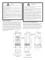
Figure 5: Dimensions (Inches)
CONTROL MOUNTING
Mount the ETC to a wall or any at surface using a combinaon of any
two or more of the sloed holes located on the back of the control
case. The control’s components are not posion sensive, but should
be mounted so that they can be easily wired and adjusted. Avoid
excessive condions of moisture, dirt, dust and corrosive atmosphere.
The ETC has provisions for 1/2 inch conduit connecons. The conduit
hub should be secured to the conduit before securing the hub to the
plasc housing of the control. When using the conduit entry in the rear
of the case, a standard plug should be inserted into the conduit hole
in the boom. Cauon should be exercised not to damage the control
circuit board or wiring when installing
a conduit connector.
CAUTION
Read all of the informaon in these instrucons before installing
or operang the ETC control.
The schemac drawings and other informaon included in these
installaon instrucons are for the purpose of illustraon and
general reference only.
ETC controls are not to be located in areas of signicant moisture,
dirt or dust as use of the control in such environment may cause
personal injury or property damage and is likely to shorten the
control life.
It is the responsibility of the installer and the user to assure
that the applicaon and use of the ETC control is in compliance
with all applicable federal, state, and local laws, regulaons and
ordinances, including, without any limitaon, all requirements
imposed under the Naonal Electric Code and any applicable
building codes.
PRÉCAUTIONS
Lire toutes les informaons contenues dans ces instrucons avant
d’installer ou d’uliser le contrôleur ETC.
Les schémas et toutes les autres informaons gurant dans ces
instrucons d’installaon sont indiqués à des ns d’illustraon et
de référence générale seulement.
Les contrôleurs ETC ne doivent pas être placés dans des zones
ayant un taux d’humidité élevé, de la saleté ou de la poussière,
car l’ulisaon du contrôleur dans de tels environnements peut
engendrer des blessures ou des dommages matériels et est
suscepble de raccourcir la durée de vie du contrôleur.
Il est de la responsabilité de l’installateur et de l’ulisateur de
s’assurer que l’installaon et l’ulisaon du contrôleur ETC soit
faites en conformité avec tous les règlements, lois, et ordonnances
fédéraux, provinciaux, et locaux, y compris, sans y être limité,
toutes les exigences imposées par la Naonal Electric Code ainsi
que tous les codes du bâment, en vigueur.
ANTI-SHORT CYCLE COMPRESSOR DELAY
When the unit is configured for cooling and there is a call for cooling,
the relay will not activate until the Anti-short Cycle Compressor
Delay is satisfied. During an Anti-short Cycle Compressor Delay, the
temperature will alternate with Cd to indicate the Relay On is delayed.
If Relay 1 is in Anti-short Cycle Compressor Delay, the temperature will
alternate with aCd or S1 icon. If Relay 2 is in Anti-short Cycle Compressor
Delay mode, the temperature will alternate with a Cd or S2 icon.

5
CONTROL WIRING
General
• All wiring should conform to the Naonal Electric Code and local
regulaons.
• The total electrical load must not exceed the maximum rang of the
control (see Specicaons).
• Use copper conductors only.
• Electrical leads should not be taut; allow slack for temperature
change and vibraon.
Input and Output Wiring
For typical wiring diagrams, refer to Figures 6 and 7. All connecons are
made to the power (lower) circuit board. When using the 24V AC
powered models, the 24V AC input lines must enter through the
sidewall of the case. Refer to Figure 5 for locaon of the entry hole.
Analog Output
ETC models are available with an oponal 0 to 10 volt analog output.
This signal is a linear representaon of the sensor temperature with
0 volts = -30°F and 10 volts = 220°F. See gure 8 for wiring informaon
and Figure 5 for locaon of the entry hole. The reference for this output
is designated by the ”-” symbol on the wiring diagram. The output
signal is designated by the ”+” symbol.
Figure 8: 0-10 V Analog Output
Located on Power (Lower) Circuit Board
Figure 7: Typical Wiring Diagram for 24 VAC Power Input
and Line Voltage Switching.
Figure 6: Typical Voltage Wiring Diagram.
FIELD REPAIRS
Field calibrang or repairs to the ETC control must not be aempted.
Sensors and replacement controls are available through Ranco
wholesalers.
SENSOR MOUNTING
For space sensing, mount the sensor where it will be unaected by
heat/cool discharge or radiated heat sources. Spot sensing requires the
sensor to be in good contact with the surface being sensed. The sensor
can be inserted in a bulb well for immersion sensing.

Customer Service Telephone 1.800.304.6563
Customer Service Facsimile 1.800.426.0804
Robertshaw®, Ranco®, Paragon® and Uni-Line® are
trademarks of Robertshaw, its subsidiaries and/or
affiliated companies. All other brands mentioned
may be the trademarks of their respective owners.
For Technical Service
Telephone 1.800.445.8299
www.robertshaw.com
©2018 Robertshaw
02/18 –352-00008-00 Rev C
6
EXTENDING SENSOR
CAUTION: Sensor wiring splices may be made external from the control.
CAUTION: Disconnect power to control before wiring to avoid possible
electrical shock or damage to the controller.
Addional cable can be spliced to the sensor cable to increase the
length beyond the standard 8 feet. It can be extended up to 400 feet.
The cable should be at least 22 AWG or larger to keep addional
resistance to a minimum.
All splices and wire lengths added to the sensor cable should be made
according to acceptable wiring pracces and should conform to the
Naonal Electrical Code and local regulaons. Use copper conductors
only. Shielded cable is not required. The sensor is not polarity sensive.
Checkout Procedure
1. Before applying power, make sure installaon and wiring
connecons are correct.
2. Apply power to the control and observe one or more cycles
of operaon.
3. If performance indicates a problem, check sensor resistance
to determine if sensor or control is at fault.
4. To check sensor resistance, disconnect sensor and measure
the resistance across the leads while measuring temperature
at the sensor.
SENSOR REPLACEMENT
Figure 9: Sensor replacement on Display (Upper) Circuit Board.
Sensor Replacement
ETC models are available with Quick Connect Sensor feature that
allows for easy sensor replacement due to damage or wear. To access
the sensor connector, disconnect the power supply and open the
control. Remove single screw located in the center of the Display
Upper Circuit Board and carefully remove Display Board Circuit.
Remove Sensor Strain Relief to allow sensor to be removed from unit.
See Figure 5 for location of sensor strain relief. The sensor connection
is made at the P1 Connector on the Display Upper Circuit Board.
See figure 9 for connection information.
Replacement Sensor - Order
Uni-Line Number 1309007-044
(OEM Number 1309007-048)
Figure 10
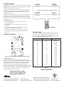
SPECIFICATIONS
The sensor is a negave temperature coecient (NTC) thermistor
sensor. The sensor resistance decreases with temperature increase.
It is .25 x 1.94 long with 8 feet #22 AWG cable. The thermistor has a
reference resistance of 30,000 ohms at 77°F (25°C).
Deg. C. Deg. F. RES. Nom.
-40 -40 1,010,000
-30 -22 531,000
-20 -4 291,200
-10 14 166,000
0 32 97,960
10 50 59,700
20 68 37,470
25 77 30,000
30 86 24,170
40 104 15,980
50 122 10,810
60 140 7,464
70 158 5,200
80 176 3,774
90 194 2,753
100 212 2,036
110 230 1,531
Figure 11:
Resistance vs Temperature
Sensor including 8 foot cable.
SENSOR CONNECTOR
-
 1
1
-
 2
2
-
 3
3
-
 4
4
-
 5
5
-
 6
6


Robertshaw Ranco ETC Two Stage Electronic Temperature Control Manuale utente
- Tipo
- Manuale utente
in altre lingue
Documenti correlati
-
Robertshaw Ranco ETC Single Stage Electronic Temperature Control - NEMA TYPE 4X Manuale utente
-
-
-
-
Altri documenti
-
Dell Stud Sensor MP2000 Manuale utente
-
Carel mchiller compact Manuale utente
-
-
Omega CN3240 Series Manuale del proprietario
-
red lion IMT Instruction Manuale utente
-
ClimateMaster Vertical-Stack Units Install Manual
-
LG LXN0356QC.ANONE Manuale del proprietario
-
Honeywell T4039J Manuale utente