
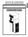
TELECOM AIR CONDITIONERS
INSTALLATION INSTRUCTIONS
l Please read this instruction sheet completely before installing the product.
l When the power cord is to be replaced, replacement work shall be performed by authorized
personnel only.
l Installation work must be performed in accordance with national wiring standards by authorized
personnel only.
ENGLISH
3.0TR SINGLE PHASE: LX-0356QC
3.5TR SINGLE PHASE: LX-0456QC


INDEX
3
1.The following should be always observed for safety ...................
2. Product Specification ..........................................................................
2.1 Product Description .............................................................................
2.2 Inspection ............................................................................................
2.3 Technical specification .......................................................................
3. Installation Standard ..........................................................................
3.1 Pre-check ...........................................................................................
3.2 Levelling of Airconditioner ..................................................................
3.3 Shelter Cut - out sealing ......................................................................
3.4.Condensate Drain Pipe .......................................................................
3.5 Air purging of connecting pipes & Indoor unit ......................................
3.6 Filter Cleaning .....................................................................................
3.7 Installation Drawing - Cases 1& 2 ...............................................
3.8 Installation Drawing - Foundation ......................................................
4. Controller ............................................................................................
4.1 Display & Indicators ...........................................................................
4.2 Pre-Startup instructions ....................................................................
4.3 Operations ...................................................................................
4.4 LCD menu details ........................................................................
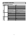
5.Trouble Shooting ...............................................................................
5.1 Symptoms & Problems .....................................................................
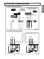
6.Electrical wiring diagram ..................................................................
6.1 Indoor wiring Diagram .......................................................................
6.2 Outdoor wiring Diagram ....................................................................
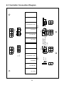
6.3 Controller Connection Diagram .........................................................
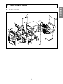
7.Exploded view .....................................................................................
7.1 indoor unit ..........................................................................................
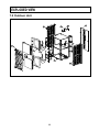
7.2 Outdoor unit .......................................................................................
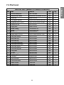
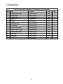
7.3 Part List ........................................................................................
4~5
6
6
6
7
8
8
9
9
9
10
10
11~14
15
16
16
17
18~19
20~27
28
28
29
29
29
30
31
31
32
33~34
ENGLISH

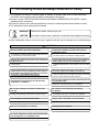
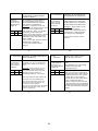
1. The following should be always observed for safety
The supplied unit requires 3 phase supply to operate, so please make sure to have authorised
Be sure to read "THE FOLLOWING SHOULD BE ALWAYS OBSERVED FOR SAFETY" before
installing the air conditioner.
Be sure to observe the cautions specified here as they include important items related to safety.
The indications and meanings are as follows.
After reading this manual, be sure to keep it together with the owner's manual in an accessible place.
Could lead to death, serious injury, etc.
Could lead to serious injury in particular environments when operated incorrectly.
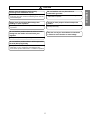
WARNING
CAUTION
connection by the supply authority before connecting to the system.
Do not install it yourself (customer).
Perform the installation securely referring to the
installation manual.
Install the unit securely in a place which can bear the
weight of the unit.
Attach the electrical part cover to the indoor unit and
the service panel to the outdoor unit securely.
Be sure to use the part provided or specified parts for
the installation work.
Check that the refrigerant gas do not leak after
installation is completed.
Use the specified wires to connect the indoor and the
outdoor units securely and attach the wires firmly to
the terminal board connecting sections so the stress
of the wires is not applied to the sections.
Incomplete installation could cause injury due to fire, electric shock,
the unit falling or a leakage of water Consult the dealer from whom
you purchased the unit or authorised installer.
Incomplete installation could cause a personal injury due to
fire, electric shock, the unit falling or a leakage of water.
When installed in an insufficient strong place, the unit could f all
causing injured.
Incomplete connecting and fixing could cause fire.
The use of defective parts could cause an injury or leakage of
water due to a fire, electric shock, the unit falling, etc.
If the electrical part cover if the indoor unit and/or the service
panel if the outdoor unit are not attached securely, it could result
in a fire or electric shock due to dust, water, etc.
WARNING
Perform electrical work according to the installation
manual and be sure to use an exclusive circuit.
If the capacity of the power circuit is insufficient or there is
incomplete electrical work, it could result in a fire or an electric
shock.
4
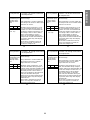
Be cautious when unpacking and installing
the product.
Be sure the installation area does not deteriorate
with age.
If the base collapses, the air conditioner could fall with it,
causing property damage, product failure and personal injury.
Sharp edges could cause injury. Be especially careful of the
case edges and the fins on condenser and evaporator.
Always install a dedicated circuit and breaker.
Do not modify or extend the power cable.
There is risk of fire or electric shock. Improper wiring or installation may cause fire or electric shock.
Always ground the product.
Use the correctly rated circuit breaker.
There is risk of fire or electric shock. There is risk of fire or electric shock.
Do not use a defective or under rated circuit breaker.
Use this appliance on a dedicated circuit.
There is risk of fire or electric shock.

Perform the drainage/piping work securely
according to the installation manual.
If there is a defect in the drainage/piping work, water
could drop from the unit and household goods could be
wet and damaged.
Do not install the unit in a place where an
inflammable gas leaks.
If gas leaks and accumulates in the area surrounding the unit, it
could cause an explosion.
CAUTION
Always check for refrigerant R-22 leakage after
installing or repair of product.
Low refrigera nt R-22 levels may cause malfun ctionin g
of product.
Use two or more people to lift and transport the
product.
Avoid personal injury.
Do not install the product where the noise or hot air
coming from the outdoor unit could harm your
neighbors.
It may cause problem to your neighbors.
Keep the level of your airconditioner as mentioned
in manual to avoid vibration or water leakage.
Do not install the product where it will be exposed to
sea wind (Salt spray) directly.
It may cause corrosion on product. Corrosion,
particularly on the condenser and evaporator fins,
could cause product malfunction or inefficie nt operation.
5
ENGLISH

6
2. PRODUCT SPECIFICATION
2.1 PRODUCT DESCRIPTION:
Airconditioner is composed of evaporator unit and condensing unit. Evaporator
unit is positioned on top of condensing unit and connected with interconnection
pipes. Condenser section consists of compressor, propeller fan, fan motor and
condenser coil. And Evaporator section consists of evaporator coil, centrifugal
blower, blower motor and logical controller. Airconditioner is equipped with dual
independent Airconditioning cycle for reliability measures.
2.2 INSPECTION:
1. Check the damage after unit is unloaded, report promptly to the carrier, any
damage found to unit. Do not drop the unit.
2. Open the Packing carefully to check the unit in upright position.
3. Check the unit dents, paint damage, tube pinch offs, tube parts touching with
sheet metals, mechanical components and electrical wires connections.
4. Condensing unit is precharged with R-22 gas from factory. Ensure gas in
condensing unit before installation.

7
UNITS LX-0356QC
TR 3.0
BTU/HR 18600 X 2
KCAL/HR 4650 X 2
KCAL/HR 4185 X 2
KCAL/HR 465 X 2
NOS 2
Rotary
NOS 2
Hitachi
SH315CV-C7HU
Sq.M 0.223
NOS 2
FPI/No 14/2
Cu/Al-Precoat
Sq.M 0.272
NOS 2
FPI/No 14/3
Cu/Al-Precoat
INDUCTION MOTOR
NOS 2
230V-1PH-50Hz
RPM 960
mm 17
B CLASS
INDUCTION MOTOR
NOS 2
230V-1PH-50Hz
mm 12.7
B CLASS
RPM 880
CENTRIFUGAL,FORWARD
CURVE, DIDW
NOS 2
PROPELLER -AXIAL
Plastic
NOS 2
mm 19
mm 12.7x2
mm 9.52x2
mm 665
mm 762
mm 938
KGS 90
KGS 85
mm 665
mm 550
mm 1080
KGS 110
KGS 105
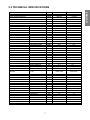
DESCRIPTION
COMPRESSOR TYPE
QTY
MAKE
MODEL
EVAPORATOR FACE AREA
QTY
FIN DENSITY/ROWS
MATERIAL OF TUBE/FIN
CONDENSER FACE AREA
QTY
FIN DENSITY/ROWS
MATERIAL OF TUBE/FIN
INDOOR MOTOR TYPE
QUANTITY
POWER SUPPLY
SPEED
SHAFT DIAMETER
CLASS OF INSULATION
OUTDOOR MOTOR TYPE
QUANTITY
POWER SUPPLY
SHAFT DIAMETER
CLASS OF INSULATION
FAN SPEED
BLOWER
TYPE
QTY
FAN TYPE
FAN MATERIAL
QTY
CONNECTIONS CONDENSATE DRAIN SIZE
GAS OUTLET SIZE OD (nos)
LIQUID INLET SIZE,OD (nos)
OVERALL DIMENSION-INDOOR (A)WIDTH
(B)DEPTH
©HEIGHT
WEIGHT-INDOOR WEIGHT GROSS
WEIGHT NET
OVERALL DIMENSION-OUTDOOR WIDTH
DEPTH
HEIGHT
WEIGHT-OUTDOOR WEIGHT GROSS
WEIGHT NET
SENSIBLE COOLING CAPACITY
LATENT COOLING CAPACITY
NO OF REFRIGERANT CIRCUITS
NOMINAL COOLING CAPACITY
TOTAL COOLING CAPACITY
2.3 TECHNICAL SPECIFICATIONS
ENGLISH
LX-0456QC
3.5
21000 X 2
5250 X 2
4725 X 2
525 X 2
CFM 825 X 2AIRFLOW
960 X 2
2
Rotary
2
Hitachi
SH315CV-C7HU
0.223
2
14/3
Cu/Al-Precoat
0.272
2
14/3
Cu/Al-Precoat
INDUCTION MOTOR
2
230V-1PH-50Hz
1100
17
B CLASS
INDUCTION MOTOR
2
230V-1PH-50Hz
12.7
B CLASS
880
CENTRIFUGAL,FORWARD
CURVE, DIDW
2
PROPELLER -AXIAL
Plastic
2
19
12.7x2
9.52x2
665
762
938
92
87
665
550
1080
110
105

8
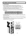
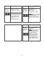
3.1 PRE-CHECK:
1. Remove the packing wooden base from indoor & outdoor unit.
2. Place the outdoor unit over mounting base (Concrete or I –beam) and
place antivibration pad and mount as per installation instructions.
FLARED TYPE INTERCONNECTING PIPING SIZE X QTY.
SUCTION LINE INTERCONNECTING PIPING 1/2 inch X 2
LIQUID LINE INTER CONNECTING PIPING 3/8 inch X 2
7. Align the centre of the pipings (2 suctions & 2 liquids) and sufficiently tighten the
flare nut with fingers.
8. Finally tighten the flare nut with torque wrench until the wrench clicks (40~80kgf).
When tightening the flare nut with torque wrench, ensure the direction of
tightening follows the arrow of wrench.
6. Wrap Teflon tape in direction of thread to the connectors & service valve before
placing flared tubing.
3. INSTALLATION STANDARD
3. Positioned the Indoor unit over Top of condensing unit and bolted indoor
with outdoor after fixing indoor to shelter cut-out portion.
4. Check there should not be any dents, dust in interconnecting piping.
5. Prepare inter connection pipe to connect indoor unit with outdoor unit as
per following.
Liquid
Interconnection
Suction
Interconnection
(A)

9
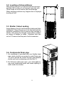
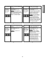
3.2. Levelling of Airconditioner
After placing the unit on Channel/concrete structure
maintain the levelling of unit towards rear side with
10mm slope so as to ensure free flow drainage.
Water seepage problem may happen due to improper
levelling of unit.
3.4. Condensate Drain pipe
3.3. Shelter Cutout sealing
Angle flanges (4 nos) to be fixed with shelter wall after
installation. These flanges are to be fixed with shelter
wall after installation so as to prevent any leakage in
shelter. after fixing the flanges; apply silicon sealant
on edges of flanges to make complete leak free
cut-out. These are not the part of unit accessories.
1. Air conditioner is provided with one flexible drain
pipe, which shall be connected to metal Drain pipe
of unit & should be routed through gap between
shelter wall and condensing unit (see fig. C).
2. Do Not leave drain pipe open, your airconditioner
may suck condensate water and cause splitting of
water inside the shelter.
(B)
(C)
ENGLISH

10
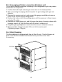
The air which contains moisture remaining in the refrigeration cycle may cause
malfunction of compressor.
1. Confirm the both liquid valves& gas valves are set to closed position.
2. After connecting the piping, check the joints for gas leakage with gas leal
detector.
3. Remove the service port nut, and connect the gauge manifold and vacuum
pump to the service port by charge hose.
4. Vacuum the indoor unit & connecting pipes until the pressure in them lowers
to below 76 cmHg.
5. Remove the valve stem nuts. and fully open the stems of service valves with
hexagon wrench. & Tight the flare nuts of indoor & outdoor unit.
6. Purge the gas qty-80grams in each circuit to remove moist air contents.
7. Disconnect the charge hose and fit the nut to the service port.
(Tightening torque:1.8kg.m)
3.5. Air purging of inter connection & Indoor unit
The Airconditioner is equipped with fine air filter (2 nos.). The Air filter are at
front of unit shall be checked and cleaned every month or more often
if necessary.
3.6. Filter Cleaning
Air-filter

11
AC UNIT
SHELTER WALL
CONCRETE
BASE
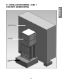
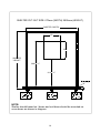
3.7. INSTALLATION DRAWING - CASE 1 :
CONCRETE BASEMOUNTING
ENGLISH

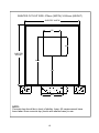
NOTE:
Concrete top should be in level of shelter base. All measurement have
been taken from concrete top (levels with shelter base) in mm.
SHELTER CUT-OUT SIZE: 675mm (WIDTH) X 955mm (HEIGHT)
12
SHELTER "WIDTH"
675
955
2065
SHELTER
"HEIGHT"
1110
950

13
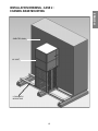
INSTALLATION DRAWING - CASE 2 :
CHANNEL BASE MOUNTING
AC UNIT
SHELTER WALL
I-CHANNEL\
MOUNTING
ENGLISH

14
NOTE:
Shelter should based on I beam and unit base should be mounted on
cross beam as shown in diagram.
SHELTER CUT-OUT SIZE: 675mm (WIDTH) X955mm (HEIGHT)
675
955
2065 + "Y"
1110 + "Y"
SHELTER
"HEIGHT"
SHELTER "WIDTH"

15
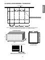
3.8. INSTALLATION DRAWING : FOUNDATION
950
680
X
CONCRET BASE
NOTE : REAR VIEW OF
L FLANGE FITTED
TO SHELTER WALL.
NOTE : IN CASE OF USING FOUNDATION BOLT (OPTIONAL) CUTOUT HEIGHT
SHALL BE INCREASED AS PER HEIGHT OF FOUNDATION BOLT.
ANTI VIBRATION PAD (AV PAD-4 NOS)
NOTE : ALWAYS PLACE AV PAD (4 NOS) AT
BOTTOM OF BASE MOUNTING CHANNEL
ENGLISH
SHELTER WALL
160
355
355
360
160
120
475
475
MOUNTING HOLE DIA 10X4 (TYP.)
675
955

HP / LP
RH %
AMB
Lock Parameter
7
8
9
10
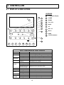
LEGENDS
7 Segment display
COMP
DAMP
FC / EFC
MCB
CT
1
2
3
4
5
6
4.1. DISPLAY & INDICATORS
16
4. CONTROLLER
1
3
5
6
7
4
2
8
9
10
2
1
°c
COMP
BLOW
DAMP
AMB RH%
FC / EFC MCB CT HP / LP
COMP DAMP FC / EFC MCB CT HP / LP
BLOW
UNIT
1
UNIT
2
RH AMB
CT1 CT2
SET
RESET
LED indications and status
LED LED Status Description
FC ON
OFF
Flashing
ON
OFF
ON/OFF
DAMPER
BLOWER
Flashing
ON/OFF
Flashing
COMP
MCB
CT
HP/LP
ON
Flashing
ON
Flashing
ON
AMB PROBE
RH
PROBE
ON(Red)
Flashing
Free Cooling in Progress
Free/Emergency Cooling is not in Progress
Emergency Cooling is in Progress
Damper Actuator in motion
Damper Actuator Stopped
BLOWER is ON//OFF
BLOWER in time delay
COMPRESSOR is ON/OFF
COMPRESSOR in time delay
Represents the respective units
MCB FAULT
CT FAULT (UL/OL/CP)
HP FAULT
LP FAULT
Ambient Temperature Probe Fail
RH Probe fail (RH>99%)
RH Probe fail (RH<10%)
Flashing (in prog.
and set mode)

17
KEY PAD
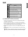
4.2. CONTROLLER: Pre-Start up Instructions
Check the transit damage to controller before carrying out power supply
connection to controller in AC.
Connect the proper Power Supply to air conditioner as per specification.
Place the ambient and humidity sensor in correct position. Room Sensor to
be fix on specified location to sense correct room temperature.
If Power Key is Pressed for 4 Secs the Unit will toggle between ON / OFF
Status.
If Power Supply of Units is not connected properly, then controller will give
MCB error.
Check For Proper connection from Supply to the controller input terminal.
ENGLISH
If MCB error still exists then Reverse Phase and Neutral Of the Supply.
Key Functions
Key Description
Key to view compressor1 current and up key.
Key to view compressor2 current and down key.
Key to view Ambient Temperature.
Key to view Shelter Humidity (%RH).
To save parameters and to enter set mode.
To reset any pending faults in the controller.
To switch ON or switch OFF UNIT1.
To switch ON or switch OFF UNIT2.
SET
CT2
CT1
RESET
AMB
RH
UNIT1
UNIT2

18
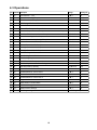
S.N.
Parameters
Description
Range Factory set
1
2
3
4
5
6
7
8
9
10
11
12
13
14
15
16
17
18
19
20
21
22
23
24
25
26
27
28
29
4.3 Operations
P1
P2
P3
P4
P5
P6
t2
t3
t4
Ad
C0
C1
C2
C3
C4 & C5
L1
L3
L4
L5
L6
D0
D1
D2
D3
LP
E1
PA
FS
EP
Unit Selection - 1 & 2
Max. Allowable High Temp. Limit
Min. Allowable Low Temp. Limit
Diff. Setting of Set Pt. 1 & 2
Probe Calibration
Restart Time Delay bet. Comp. 1 & 2
Start 2nd Comp in case 1st Comp. cannot achieve the lower Set point
Set Min. Off time between the two Comp.
Avoid Overloading of either Comp.
Set Power on time delay for High Temp. Alarm
Set Low Current Limit for Comp. 1
Set low Current Limit for Comp. 2
Set High Current Limit for Comp.1
Set High Current Limit for Comp. 2
Set Time Delay for Current Alarms
Free Cooling Enable/Disable for Unit 1
Free Cooling Set point
Set Differential for Damper
Set Humidity Limit to allow Free Cooling
Set Differential for Humidity
Enable/Disable HP Fault for Unit 1
Enable/Disable HP Faut for Unit 2
Enable/Disable LP Fault for Unit 1
Enable/Disable LP Fault for Unit 2
Keypad Lock
Relay Status on Probe Failure
Password Change
Default Restore Settings
End Programming
0 è 2
XX è 50°C
0° è XX °C
1° è 20°C
-10° è +10°C
0 è 20 Min
0 è 30 Min
0 è 15 Secs
0 è 12 Hrs
0 è 20 Min
1 è C2 A
1 è C3 A
C0 è 20 A
C1 è 20 A
0 è 30 Min
0 è 1
10° è XX °C
1° è 4°C
10% è 99%
3% è 10%
0 è 1
1 è 1
2 è 1
3 è 1
0 è 1
0 è 2
0 è 99
0 è 1
0
42°C
14°C
2°C
0°C
3 Min
0
5 Sec
12 Hrs
20 Min
1A
1A
10A
10A
1 Min
0
16°C
2°C
70%
5%
1
1
1
1
1
0
48
0
Exit Programming Mode

19
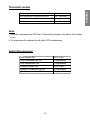
Thermostatic operation
Note:
If both the compressors are OFF due to Thermostatic operation, duty blower will continue
to run.
The compressor & condenser fan will switch OFF simultaneously.
Duty blower ON 55 ± 5 sec
Duty Condenser fan ON Programable
Duty compressor ON Programable
Standby blower ON 55 ± 5 sec
Standby Condenser fan ON Programable
Standby compressor ON Programable
Switch ON sequencing:
Duty compressor & condenser fan cut-OFF Set-1°C
Duty compressor & condenser fan cut-IN Set + Differential °C
Set + Differential °C
Standby compressor & condenser fan cut-OFF Set °C
Standby compressor & condenser fan cut-IN
ENGLISH

20
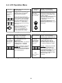
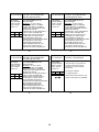
4.4. LCD Operation Menu
3. P1 parameter
Function : Unit selection
parameter of Controller .
To change
P1 parameter,
Press set key
.
when display
shows P1
Use UP/DOWN key to set
desired range.
When P1 is set to
0 Both Cooling units are selected.
1 Cooling Unit 1 is selected.
2 Cooling Unit 2 is selected
Setting this parameter
at 1 will select Unit1 only,unit2
will be off. Setting this parameter
to 0 will allow to function both the
units simeoutanously
Example :
Min. Max. Fac.
0 2
0
3
4. P2 parameter
Function : To set maximum
allowable high temperature limit.
To change
P2 parameter,
Press set key
.
when display
shows P2
Use UP/DOWN key to set
desired range. Once set at a
particular range, this will not
allow both set points to go above
this range and below P3 setting.
Setting this parameter
at 35 C will not allow both set
points to go above 35 C. Also if
the temperature reaches 35 C, the
display will show Ht (High
Temperature), indicating that the
temperature has reached or gone
above the range in this
parameter.
Example :
0
0
0
Min. Max. Fac.
XX C
0
50 C
0
42 C
0
Ht
4
XX C--Largest
set point
0
1
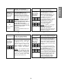
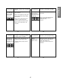
1. Set Point Function : To set the cutout point
of the controller.
Press & hold
set key for 4
seconds and
release.
Set point 1
Set Point 2
Display will show 0 and flash. Press
Up/Down keys to enter password.
User can go into set mode by
entering correct password.
Comp1LED will flash along with
respective setpoint1 for compressor
1. The setpoint1 range can now be
changed by using the UP/DOWN
keys. After achieving the desired
range, press the set key and
you will see !----" which confirms
that the set point has been stored
in memory.
Comp2 LED will flash along with
respective setpoint 2 for
compressor 2. In the similar
manner use UP/DOWN key to
set the desired range and press
set key to confirm the settings.
Min. Max. Fac.
0 C
0
20 C
0
50 C
0
SET
Min. Max. Fac.
0 C
0
50 C
0
24 C
0
SET
2
2. Parameter
Setting
Hold up &
down keys
simultaneously
for 4 seconds.
Display will show 0 & flash. To enter
programming mode enter correct
password by using Up/Down keys
and press set key.
Once user enters correct password
display will show P2 and flash.
To go to other parameters, use
up / down keys.
If user enters incorrect password,
controller will come out of
programming mode and will display
temperature.
Function : To set the other
parameters of the controller.
CT2
CT1
La pagina si sta caricando...
La pagina si sta caricando...
La pagina si sta caricando...
La pagina si sta caricando...
La pagina si sta caricando...
La pagina si sta caricando...
La pagina si sta caricando...
La pagina si sta caricando...
La pagina si sta caricando...
La pagina si sta caricando...
La pagina si sta caricando...
La pagina si sta caricando...
La pagina si sta caricando...
La pagina si sta caricando...
La pagina si sta caricando...
La pagina si sta caricando...
-
 1
1
-
 2
2
-
 3
3
-
 4
4
-
 5
5
-
 6
6
-
 7
7
-
 8
8
-
 9
9
-
 10
10
-
 11
11
-
 12
12
-
 13
13
-
 14
14
-
 15
15
-
 16
16
-
 17
17
-
 18
18
-
 19
19
-
 20
20
-
 21
21
-
 22
22
-
 23
23
-
 24
24
-
 25
25
-
 26
26
-
 27
27
-
 28
28
-
 29
29
-
 30
30
-
 31
31
-
 32
32
-
 33
33
-
 34
34
-
 35
35
-
 36
36


LG LXN0356QC.ANONE Manuale del proprietario
- Tipo
- Manuale del proprietario
- Questo manuale è adatto anche per
in altre lingue
- English: LG LXN0356QC.ANONE Owner's manual
Documenti correlati
Altri documenti
-
Sanyo 26K72R Manuale utente
-
Rexel 11398201 Scheda dati
-
Robertshaw Ranco ETC Two Stage Electronic Temperature Control Manuale utente
-
-
Liebert 272014 Manuale utente
-
-
Carel mchiller compact Manuale utente
-
Dell Stud Sensor MP2000 Manuale utente
-
 Mosa GE 10000 HZDM Manuale del proprietario
-
