
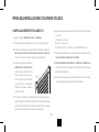
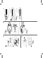
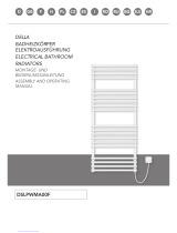
HEATING ELEMENT
TERMA VEO SMART WI-FI
MANUAL
TOPNÁ TYČ | DIE HEIZPATRONE | CALENTADOR | KIT RÉSISTANCES | ELEMENTO ELETTRICO
RISCALDANTE | GRZAŁKA | ЭЛЕКТРОНАГРЕВАТЕЛЬ
TERMA VEO SMART WI-FI
NÁVOD K OBSLUZE | GEBRAUCHSANWEISUNG | MANUAL DE INSTRUCCIONES | MODE
D’EMPLOI | MANUALE D’USO | INSTRUKCJA UŻYTKOWANIA | ИНСТРУКЦИЯ ПО
ПРИМЕНЕНИЮ
www.termasmart.com
ESDECZEN FR IT PL RU

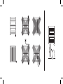
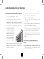
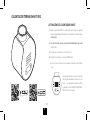
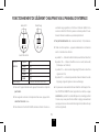
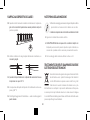
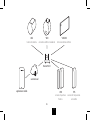
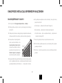
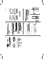
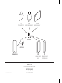
ZONE | ZÓNA | ZONA | STREFA | ЗОНА 1
ZONE | ZÓNA | ZONA | STREFA | ЗОНА 2
2
2
1
1

600 mm

4
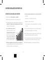
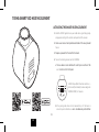
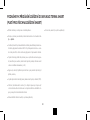
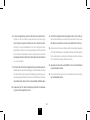
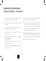
1. Electric heater is not a toy. Children under the age of 3 should not be
allowed within close proximity of the device without the supervision of
an adult.
Children aged 3 to 8 should only be allowed to operate the heater when
it has been properly installed and connected. The child must be under
adult supervision or have been trained to safely operate the device while
understanding the risks.
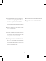
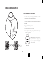
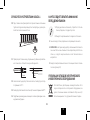
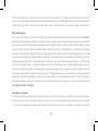
2. To ensure the safety of very small children, install the electric dryer so that
the lowest tube is at least 600 mm above the oor.
3. Do not install the heater under an electrical socket point.
4. Your electric heater should be lled with a carefully measured amount of
liquid. In the case of loss of heang medium, or in any other case which
demands its supplementaon, contact your supplier.
ELECTRIC RADIATOR
GUIDE TO SAFE INSTALLATION AND USE
5. The device should only be installed by a qualied installer in accordance
with the applicable regulaons regarding safety and all other regulaons.
6. All installaons to which the device is connected should comply with
regulaons applicable in the country of installaon and use.
7. Extension leads or electric plug adapters should not be used in order
to supply power to the heater.
8. The electric installaon to which the heater is connected should have
the right current dierenal and overcurrent relay (R.C.D.) of 30 mA.
With the permanent installaon (cable connecon without plug) it is
also mandatory to have an omni-pole cut-out for disconnecng the de-
vice on all poles, by points of contact with the clearance of 3 mm.
9. The device version labelled PB or MS can be installed in bathrooms in
zone 1, as dened by applicable law, subject to any addional regula-
ons concerning electrical installaons in wet areas. Other versions of
the device can be installed in Zone 2 or beyond.

5
EN
10. Ensure that the heater has been installed on a wall in accordance with
its installaon manual.
11. Note: Some parts of the radiator can be very hot and can cause burns. Pay
special aenon to the presence of children or people with disabilies.
12. When drying fabrics, pay aenon to the permissible temperature for
them. ATTENTION! Detergent residues may permanently stain the ra-
diator surface, in parcular the chrome plang. Such cases are not sub-
ject to complaint.
13. The device is recommended for use solely as described in the manual.
14. Please forward this instrucon manual to the end user.

6
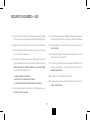
1. Fing and connecon of the heang element should only be performed
by a qualied installer.
2. Connect the unit to a sound electrical installaon (see the rangs on
the heater).
3. Switching on the heang element in the open air to test the device is
permied for a maximum of 3 seconds.
4. Never test a heang element that is already installed. Do not turn the
heang element on in an empty radiator!
5. Ensure that the power cord does not touch the hot parts of the heat-
ing element or radiator.
6. Before installing or removing the device, make sure it is disconnected
from the power source.
ELECTRIC HEATING ELEMENT
SAFETY REQUIREMENTS — INSTALLATION
7. Do not open the device — any interference with internal components
will invalidate the warranty.
8. The heang element’s power output should not exceed the radiators
power output for the parameters 75/65/20° C.
9. The pressure in the radiator must not exceed 1 MPa (10 bar). Ensure
that an air cushion is preserved in electric radiators. In central heang
systems, leave one valve open to prevent pressure build up due to the
thermal expansion of the liquid.
10. Fing and Installaon of the device must be carried out in accordance
with all local regulaons for electrical safety, including installa on within
permissible locaons only. Observe bathroom electrical zone regulaons.
11. The device is intended for home use only.

7
EN
1. Ensure that minors aged 8 and above or those with a physical or mental
disability are supervised if operang the device.
2. The device is not a toy. Keep it out of the reach of children.
3. Cleaning of the equipment by children under 8 years of age is only permied
under appropriate supervision.
4. The heang element must be fully submerged in the heang liquid dur-
ing its operaon. When operang the heang element in a radiator con-
nected to a central heang system (dual fuel version):
— bleed the radiator regularly,
— make sure, that one valve is always open,
— periodically check the liquid level in the radiator.
SAFETY REQUIREMENTS — USE
5. Regularly check the device for damage to ensure it is safe to use.
6. If the power cord is damaged the device should not be used. Unplug
the device and contact the manufacturer or distributor.
7. Do not allow ooding into the heang element casing.
8. Do not use the heang element in heang systems where the water
temperature exceeds 82° C (class I only).
9. The heang element and radiator can heat up to high temperatures. Please
be cauous — avoid direct contact with the hot parts of the equipment.
10. Do not open the heang element casing.
11. The device must be disconnected from the mains during cleaning and
maintenance.

8
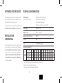
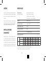
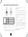
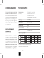
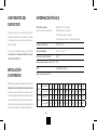
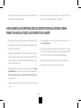
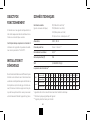
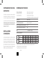
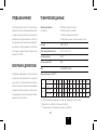
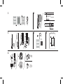
TECHNICAL INFORMATION
Model markings PB (Straight cable without plug)*
(power connecon type) PW (Straight cable with plug)
SW (Spiral cable with plug)
MS (screw connecon + on/o switch)*
Power supply 230 V / 50 Hz
Appliance class Class I / Class II (**)
Towel rail connecon thread G 1/2"
IP code*** IPx5
WiFi 2,4 GHz 802.11 b/g/n
Heat outputs available (**)
Class I power [W] 120 200 300 400 —600 800 1000 1200 1500 1800 2000
length [mm] 325 285 310 345 —375 485 575 670 860 1025 1130
Class II power [W] 100 200 300 400 500 600 800 1000 1200 1500 1800 2000
length [mm] 165 220 260 350 350 465 600 670 670 670 670 670
* device intended to be connected permanently to the system
** details on the rang label of the device
*** degree of protecon provided by enclosure
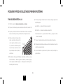
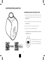
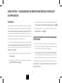
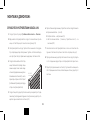
INTENDED USE OF DEVICE
The heang element is an electric device intended
solely for installaon in radiators (standalone or con-
nected to the central heang system).
Heang element power output should be matched
with radiator output for parameters of 75/65/20° C.
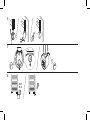
INSTALLATION
OR REMOVAL
Detailed informaon demonstrang the dierent
ways of installing or removing a radiator heang el-
ement is available from the manufacturer or import-
er (see footnotes at the end of the manual). Below
we list some basic requirements and principles which
must be followed to ensure long term, reliable oper-
aon of the product.

9
EN
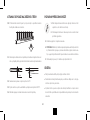
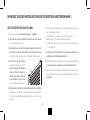
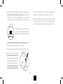
BEFORE INSTALLATION OR FIRST USE:
APPLIES TO CLASS I AND CLASS II DEVICES
1. Read the chapter: Safety requirements — Installaon.
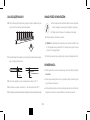
2. Fit the heang element using the correct spanner (size 24).
3. The heang element must be installed at the boom of the radiator, per-
pendicular to the radiator pipes, while preserving space for the proper
circulaon of the heang medium.
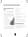
4. Use a suitable heating medium for
lling the electric radiator, i.e. (water,
special products based on water and
glycol for use in central heang sys-
tems, or oil which complies with the
requirements of the manufacturer of
the radiator and heang element).
5. Make sure an adequate air cushion is present to protect against exces-
sive pressure build up within the electric only radiator (or leave one of
the radiator valves open in central heang system).
6. Follow the subsequent guidelines when connecting the electrical
installaon:
a. Brown wire — live connecon to the circuit (L)
b. Blue wire — connect to neutral (N)
c. Yellow & green wire — (tylko w urządzeniach klasy I) — earth connec-
on (PE)
7. Do not switch the heang element on if it is not fully immersed in ra-
diator heang medium (applies also to the rst use)!
8. Before lling the radiator with heang medium, ensure that the heat-
ing element is ed properly and that it is water ght.
9. In central heang installaon radiator must be ed with the valves en-
abling disconnecon of the radiator from the rest of the system.
10. For detailed installaon hints — see the last pages of this manual.
8% (20°C)

10
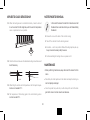
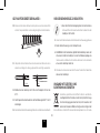
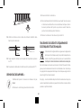
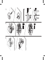
APPLIES TO CLASS I DEVICES ONLY
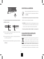
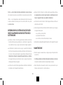
11. When the heang element is installed horizontally, it must be rotated
to such an extent that the single tube, which houses the temperature
sensor, is posioned as low as possible.
150°
12. Check the distances between the individual heang element tubes and
bend if necessary.
2-3 mm
5 mm
13. When lling the radiator with hot liquid insure that the liquid tempera-
ture does not exceed 65° C.
14. The temperature of the heang agent in the central heang system
must not exceed 82° C.
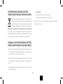
NOTES PRIOR TO REMOVAL
1. Disconnect the device from electric circuit and ensure that
the radiator has cooled down before you start disassembling
the radiator.
2. Release the screw at the back of the controller casing.
3. Take o the controller from the heang element.
4. Be careful — electric only radiator lled with heang liquid may be very
heavy. Ensure all necessary safety measures.
5. For disassembling the heang rod use a spanner no 24.
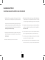
MAINTENANCE
• Before performing maintenance, always disconnect the device from the
mains.
• Periodically check the liquid level in the radiator and keep the heang ele-
ment completely submerged.
• Clean the product only when dry or with a damp cloth and a lile deter-
gent which does not contain solvents and abrasives.

11
EN
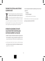
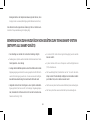
TREATMENT OF ELECTRICAL AND ELECTRONIC
EQUIPMENT WASTE:
Pursuant to the regulaons in force for used electric and electron-
ic equipment, products marked with the symbol of separate col-
lecon cannot be placed with other municipal waste. Due to the
content of harmful substances, electronic products not subjected
to the selecve sorng process may be dangerous to the natural environment
and to human health. The correct separate collecon of used electrical and
electronic equipment prevents negave impacts on the environment.
INFORMATION CONCERNING THE WASTE
COLLECTION SYSTEM FOR ELECTRICAL AND
ELECTRONIC EQUIPMENT IS AS FOLLOWS:
• A distributor accepts and collects electrical and electronic equipment waste
from households free of charge, provided that the equipment is of the
same type and performs the same funcons as the equipment purchased,
• a collecng operator have the right to refuse to accept the waste equip-
ment if it poses a threat to the health or life of individuals receiving the
equipment due to contaminaon,
• the user of equipment intended for households may hand over the used
equipment to:
— a distributor,
— a waste processing plant,
— collecng municipal waste in the commune.
Further informaon can be found on the government website:
www.hse.gov.uk/waste/waste-electrical.htm

12
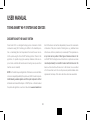
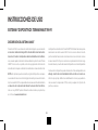
USER MANUAL
TERMA SMART WI-FI SYSTEM AND DEVICES
DESCRIPTION OF THE SMART SYSTEM
Terma Smart Wi-Fi is an intelligent heang system, all elements of which
communicate using Wi-Fi technology. In addion to the standard opera-
on, i.e. maintaining the set air temperature in the rooms, the user can con-
trol the system using the Terma SMART mobile applicaon. Thanks to this
applicaon, it is possible to program seven-day schedules, iniate an ear-
ly start mode, and divide the heated area into heang zones (several other
funcons are also included).
NOTE: For the inial set-up and registraon of the devices, a router with Inter-
net access is required (provided by the system user). A Wi-Fi router is responsi-
ble for delivering a wireless signal to each of the system components. Further
informaon can be found in the chapter — SMART System — informaon about
the system and applicaon, as well as on the website www.termasmart.com
Each of the devices can funcon independently, however, the recommend-
ed structure of the system consists of heang zones, e.g. individual rooms
in the house, which may include one (as a maximum) VTS temperature sen-
sor per room and any number of other types of devices and sensors. Ter-
ma SMART Wi-Fi heang devices will funcon at an opmum level when
connected permanently to a local Wi-Fi network with Internet access. The
devices will also funcon without access to the Internet, or even without
a Wi-Fi connecon, but in this case the previously loaded schedule will be
implemented, and many of the device funcons will remain unavailable.

13
EN
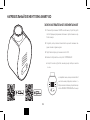
TERMA SMART VEO HEATING ELEMENT
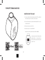
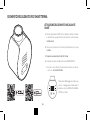
ACTIVATING THE SMART HEATING ELEMENT
1. Install the SMART applicaon on your mobile device, grant the appropri-
ate approvals relang to the locaon and operaon of the scanner.
2. Create a user account and provide basic details of the newly created
ʻhouse’.
3. Prepare a password for the local Wi-Fi network.
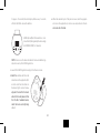
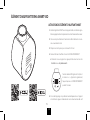
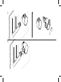
4. Turn on the heang element and start PAIRING:
a. The new device can be started with a short press on either of the
+ or − buttons on the front panel.
All LED strips will ash three mes and the + / −
buons will ash steadily, the device will go into
PAIRING MODE for 5 minutes.
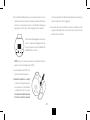
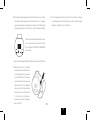
b. If the pairing mode does not start automacally, or if the device is
restarted, press both buons + and − simultaneously and hold them

14
for approx. 15 seconds (the enre display ashes every 5 seconds,
aer the third ash, release the buons.
All LED strips will ash 3 mes and the + / − but-
tons will start ashing steadily, the device will go
into PAIRING MODE for 5 minutes.).
NOTE: from now on, the device broadcasts its network address (sig-
nal) and is seen by the SMART applicaon.
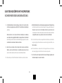
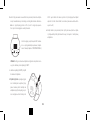
c. Launch the SMART applicaon and go to the Devices screen.
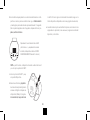
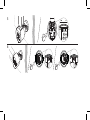
d. Select the + buon and follow the
instrucons in the applicaon (rst
scan the code from the scker on
the device (Fig.3) or enter it manu-
ally, select the local Wi-Fi network
and enter the router password, then
from the list of available devices,
select the device currently being
added).
e. When the automac part of the process is over, select the appropri-
ate zone in the applicaon (or create a new one) and enter the de-
vice name and other data.

15
EN
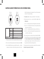
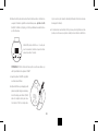
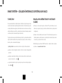
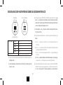
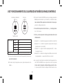
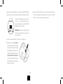
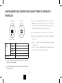
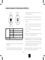
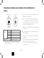
HEATING ELEMENT OPERATION VIA THE INTERFACE PANEL
LED strips
control keys
Red stripe
White stripes 5 stripes 26°C
4 strips 24°C
3 strips 21°C
2 strips 18°C
1 strip 15°C
Red stripe DRYER funcon is on
1. To wake up the device from the sleep mode, briey press any buon.
2. To raise or lower the temperature by one step, briey press + or − button.
3. To start the DRYER funcon, press and hold the + buon — a red stripe
will appear on the interface, and the heang element will start to heat
at 80% of the rated power for the duraon of 1 hour. Then the element
will return to the previous sengs.
4. To swap the + and −, buons, press and hold (> 10 s) the + buon.
5. Modes and special acons — press and hold both + and − buons
simultaneously:
a. for 5 s — the heang element turns o (single ash on the interface);
b. for 10 s — the heang element will be put to sleep (stand-by mode)
(single ash on the interface);
c. for 15 s — enter pairing mode (AP) all interface will ash 3 mes;
d. for 25 s — restore factory sengs and start the pairing mode, the de-
vice will ash as it did at set-up;
6. If the heang element’s controller panel has been blocked (the PAREN-
TAL CONTROL funcon in the control applicaon), pressing the + key
for 5 seconds will release the lock for 1 minute, which will allow you to
change the sengs manually on the device without the need to use
the applicaon (conrmaon by ashing interface).
The change made on the device manually is valid unl the next automac
temperature change saved in the schedule.

16
ADDITIONAL COMMENTS ON ADDING DEVICES TO THE TERMA SMART SYSTEM
(APPLIES TO ALL SMART DEVICES)
• Adding devices is possible only via the mobile applicaon.
• System changes are sent locally by the router, and to the cloud service by
the applicaon.
• In some Android system overlays, during pairing, the phone tries to auto-
macally switch to the remembered Wi-Fi network with Internet access
— you must manually conrm the connecon with the device’s network.
• Aer adding the heang devices to the system, they are turned o by de-
fault (they do not heat up, despite the low ambient temperature, the in-
terface bars are not lit, and the remote communicaon interval is 1 h).
• Heang devices should be added rst, followed by the sensors.
• There can be only one temperature and humidity sensor (VTS) in one he-
ang zone.
• The opon of ʻcombine into a set’ is available only for the heang element
and the thermostac head installed in the same central heang radiator,
and only during the installaon of the second device.
• The name of each device must be unique within the system.
• The name of the zone must be unique within the system.

17
EN
SMART SYSTEM — BASIC INFORMATION ABOUT THE SYSTEM AND THE
APPLICATION
HEATING ZONES
In the applicaon, a newly created ʻhouse’ should be divided into heang
zones (e.g. rooms) to which individual devices are assigned. It is possible to
select a schedule and view telemetry data for each zone. The list of all zones
is visible to the user in the Zones tab. The view of a single zone contains
a set of acons and informaon available to the user.
The temperature presented in the center of the screen of a single zone is the
current measured temperature, while the value at the boom is the set tem-
perature that depends on the mode in which the system is currently operang:
• if the Vacaon mode is acve, the Vacaon mode temperature is displayed
• if the Smart Locaon is acve, the temperature for the Smart Locaon is
displayed
• if at least one device is in the manual mode, the temperature set for the
manual mode is displayed — the icon
• otherwise, the temperature for a given me interval will be displayed ac-
cording to the schedule — icon
PRINCIPLES OF MEASURING THE TEMPERATURE
IN THE ROOM (IN THE ZONE):
• If there is a temperature and humidity sensor (VTS) in a zone, its indica-
ons are the basis for the temperature control for all devices in a given
zone (recommended conguraon);
• If there is no VTS sensor in the zone, the devices will operate based on
the average of the sensor readings of each device (or one sensor if one
device is in the zone).
A more detailed descripon of the SMART System can be found on
www.termasmart.com

18
1. Elektrický radiátor není na hraní. Dě do 3 let bez řádného dohledu by
neměly být v bezprostřední blízkos topení.
Dě ve věku od 3 do 8 let mohou topné zařízení ovládat pouze tehdy,
je-li správně nainstalováno a připojeno a dě jsou pod dohledem nebo
byly poučeny a pochopily rizika, která existují.
2. Aby byly chráněny před nebezpečím velmi malé dě, měl by být insta-
lován elektrický sušák na oblečení nebo ručníky tak, aby nejnižší trub-
ka byla nejméně 600 mm nad podlahou.
3. Radiátor neinstalujte přímo pod elektrickou zásuvku.
4. Elektrický radiátor by měl být naplněn přesně naměřeným množstvím
kapaliny. V případě ztráty topného média a jakéhokoli jiného faktoru
vyžadujícího jeho doplnění se obraťte na prodávajícího.
ELEKTRICKÝ RADIÁTOR S TOPNOU TYČÍ
BEZPEČNÁ INSTALACE A POUŽITÍ
5. Zařízení by měl instalovat pouze kvalikovaný topenář a elektrikář v sou-
ladu se všemi platnými bezpečnostními předpisy a jinými předpisy.
6. Všechna zařízení, ke kterým je zařízení připojeno, by měla splňovat pří-
slušné předpisy platné v této oblas.
7. K napájení topné tyče nesmí být používány prodlužovací kabely nebo
adaptéry elektrické zásuvky.
8. Musí být zajištěno, aby obvod v elektrické instalaci, ke které je topné
těleso připojeno, měl vhodný jisč a jisč zbytkového proudu (R.C.D.)
s citlivos 30 mA. Při trvalém připojení zařízení k sí (verze, které ne-
mají napájecí kabel se zástrčkou) je také povinný vypínač, který umož-
ňuje odpojit zařízení na všech pólech pomocí kontaktů s mezerou 3 mm.

19
CZ
9. Zařízení ve verzi označené PB nebo MS lze instalovat v koupelně v zóně
1, denované příslušnými předpisy, se samostatnými předpisy týkajícími
se implementace elektrické instalace v mokrých prostorách. Další ver-
ze zařízení lze nainstalovat do zóny 2 nebo mimo něj.
10. Ujistěte se, že je radiátor nainstalován na stěně podle pokynů pro jeho
instalaci.
11. Pozor! Některé čás radiátoru mohou být velmi horké a mohou způso-
bit popáleniny. Zvláštní pozornost by měla být věnována přítomnos
dě nebo osob se zdravotním posžením.
12. Při sušení tkanin byste měli věnovat pozornost teplotě, která je pro ně
přijatelná. POZNÁMKA! Zbytky čiscích prostředků mohou trvale po-
skvrnit povrch radiátoru, zejména pochromovaný galvanický povlak. Ta-
kové případy nepodléhají záruce.
13. Přístroj používejte pouze k určenému účelu, jak je popsáno v návodu k
použi.
14. Tento informační materiál by měl být poskytnut koncovému uživateli
radiátoru.

20
1. Instalaci topné tyče může provést pouze řemeslník s příslušnou kvalikací.
2. Připojte zařízení pouze ke správně provedené elektrické instalaci (viz
nálepka stříbrná na zadní straně tyče).
3. Je povoleno krátce zapnout topnou tyč na otevřeném vzduchu po dobu
ne delší než 3 sekundy.
4. Rozhodně nezapínejte topnou tyč v prázdném radiátoru bez topného
média!
5. Dbejte na to, aby napájecí kabel nepřišel do styku s horkými prvky ra-
diátoru nebo topné tyče.
6. Během montáže nebo demontáže nesmí být zařízení pod napěm.
7. Nezasahujte do vnitřku zařízení.
8. Výkon topné tyče nesmí být větší než výkon radiátoru pro parametry
75/65/20 °C.
TOPNÁ TYČ
BEZPEČNOSTNÍ POŽADAVKY — INSTALACE
9. Tlak v radiátoru nesmí překročit 10 atm. V elektrickém radiátoru pone-
chejte volný vzduchový polštář pro roztažnost média a v radiátoru při-
pojeném k systému ústředního vytápění ponechte otevřený 1 venl,
aby se zabránilo zvýšení tlaku v důsledku tepelné roztažnos kapaliny.
10. Zařízení instalujte v souladu se všemi místními předpisy týkajícími se
bezpečnostních požadavků elektrických zařízení, včetně přípustného
umístění a vzdálenos od zdrojů vody.
11. Zařízení je určeno pro domácí použi.
La pagina si sta caricando...
La pagina si sta caricando...
La pagina si sta caricando...
La pagina si sta caricando...
La pagina si sta caricando...
La pagina si sta caricando...
La pagina si sta caricando...
La pagina si sta caricando...
La pagina si sta caricando...
La pagina si sta caricando...
La pagina si sta caricando...
La pagina si sta caricando...
La pagina si sta caricando...
La pagina si sta caricando...
La pagina si sta caricando...
La pagina si sta caricando...
La pagina si sta caricando...
La pagina si sta caricando...
La pagina si sta caricando...
La pagina si sta caricando...
La pagina si sta caricando...
La pagina si sta caricando...
La pagina si sta caricando...
La pagina si sta caricando...
La pagina si sta caricando...
La pagina si sta caricando...
La pagina si sta caricando...
La pagina si sta caricando...
La pagina si sta caricando...
La pagina si sta caricando...
La pagina si sta caricando...
La pagina si sta caricando...
La pagina si sta caricando...
La pagina si sta caricando...
La pagina si sta caricando...
La pagina si sta caricando...
La pagina si sta caricando...
La pagina si sta caricando...
La pagina si sta caricando...
La pagina si sta caricando...
La pagina si sta caricando...
La pagina si sta caricando...
La pagina si sta caricando...
La pagina si sta caricando...
La pagina si sta caricando...
La pagina si sta caricando...
La pagina si sta caricando...
La pagina si sta caricando...
La pagina si sta caricando...
La pagina si sta caricando...
La pagina si sta caricando...
La pagina si sta caricando...
La pagina si sta caricando...
La pagina si sta caricando...
La pagina si sta caricando...
La pagina si sta caricando...
La pagina si sta caricando...
La pagina si sta caricando...
La pagina si sta caricando...
La pagina si sta caricando...
La pagina si sta caricando...
La pagina si sta caricando...
La pagina si sta caricando...
La pagina si sta caricando...
La pagina si sta caricando...
La pagina si sta caricando...
La pagina si sta caricando...
La pagina si sta caricando...
La pagina si sta caricando...
La pagina si sta caricando...
La pagina si sta caricando...
La pagina si sta caricando...
La pagina si sta caricando...
La pagina si sta caricando...
La pagina si sta caricando...
La pagina si sta caricando...
La pagina si sta caricando...
La pagina si sta caricando...
La pagina si sta caricando...
La pagina si sta caricando...
La pagina si sta caricando...
La pagina si sta caricando...
La pagina si sta caricando...
La pagina si sta caricando...
La pagina si sta caricando...
La pagina si sta caricando...
La pagina si sta caricando...
La pagina si sta caricando...
La pagina si sta caricando...
La pagina si sta caricando...
La pagina si sta caricando...
La pagina si sta caricando...
La pagina si sta caricando...
La pagina si sta caricando...
La pagina si sta caricando...
La pagina si sta caricando...
La pagina si sta caricando...
La pagina si sta caricando...
La pagina si sta caricando...
La pagina si sta caricando...
La pagina si sta caricando...
La pagina si sta caricando...
La pagina si sta caricando...
La pagina si sta caricando...
La pagina si sta caricando...
La pagina si sta caricando...
La pagina si sta caricando...
La pagina si sta caricando...
La pagina si sta caricando...
La pagina si sta caricando...
La pagina si sta caricando...
La pagina si sta caricando...
La pagina si sta caricando...
La pagina si sta caricando...
La pagina si sta caricando...
La pagina si sta caricando...
-
 1
1
-
 2
2
-
 3
3
-
 4
4
-
 5
5
-
 6
6
-
 7
7
-
 8
8
-
 9
9
-
 10
10
-
 11
11
-
 12
12
-
 13
13
-
 14
14
-
 15
15
-
 16
16
-
 17
17
-
 18
18
-
 19
19
-
 20
20
-
 21
21
-
 22
22
-
 23
23
-
 24
24
-
 25
25
-
 26
26
-
 27
27
-
 28
28
-
 29
29
-
 30
30
-
 31
31
-
 32
32
-
 33
33
-
 34
34
-
 35
35
-
 36
36
-
 37
37
-
 38
38
-
 39
39
-
 40
40
-
 41
41
-
 42
42
-
 43
43
-
 44
44
-
 45
45
-
 46
46
-
 47
47
-
 48
48
-
 49
49
-
 50
50
-
 51
51
-
 52
52
-
 53
53
-
 54
54
-
 55
55
-
 56
56
-
 57
57
-
 58
58
-
 59
59
-
 60
60
-
 61
61
-
 62
62
-
 63
63
-
 64
64
-
 65
65
-
 66
66
-
 67
67
-
 68
68
-
 69
69
-
 70
70
-
 71
71
-
 72
72
-
 73
73
-
 74
74
-
 75
75
-
 76
76
-
 77
77
-
 78
78
-
 79
79
-
 80
80
-
 81
81
-
 82
82
-
 83
83
-
 84
84
-
 85
85
-
 86
86
-
 87
87
-
 88
88
-
 89
89
-
 90
90
-
 91
91
-
 92
92
-
 93
93
-
 94
94
-
 95
95
-
 96
96
-
 97
97
-
 98
98
-
 99
99
-
 100
100
-
 101
101
-
 102
102
-
 103
103
-
 104
104
-
 105
105
-
 106
106
-
 107
107
-
 108
108
-
 109
109
-
 110
110
-
 111
111
-
 112
112
-
 113
113
-
 114
114
-
 115
115
-
 116
116
-
 117
117
-
 118
118
-
 119
119
-
 120
120
-
 121
121
-
 122
122
-
 123
123
-
 124
124
-
 125
125
-
 126
126
-
 127
127
-
 128
128
-
 129
129
-
 130
130
-
 131
131
-
 132
132
-
 133
133
-
 134
134
-
 135
135
-
 136
136


in altre lingue
- français: Terma grzałki VEO Mode d'emploi
- español: Terma grzałki VEO Guía del usuario
- Deutsch: Terma grzałki VEO Benutzerhandbuch
- slovenčina: Terma grzałki VEO Užívateľská príručka
- polski: Terma grzałki VEO instrukcja
Documenti correlati


Altri documenti
-
screwfix 1000W Manuale utente
-
Blumfeldt 10045383 Manuale del proprietario
-
Kermi 6911519 Use And Installation Instructions
-
-
Vasco EVE10 Radiator Manuale utente
-
 VOGEL&NOOT DELLA WAVE Assembly And Operating Manual
-
Clatronic RA 2802 Manuale del proprietario
-
Clatronic RA 2725 Manuale del proprietario
-
 NEO TOOLS 90-093 Manuale del proprietario

