
TH-D
IT
ITITITITDK
NL
FR
ES
DE
GB
EE
LV
LT
HR
SE
BG
SK
SI
HU
CZ
RU
NO
FI
RO
PL

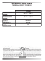
TECHNICAL DATA TABLE
TABELLA DATI TECNICI
TH-D
TEMPERATURE
RANGE
-50 °C / +115 °C
SONDE
TEMPERATURE
RANGE
-30 °C / +100 °C
POWER
SUPPLY
~220-240 V
FREQUENCY
50-60 Hz
FUSE
PROTECTION
4 A
en - Disposal of your old product
- You product is designed and manufactured with high
quality materials and components, which can be
recycled and reused.
- When this crossed-out wheeled bin symbol is attached
to a product it means the product is covered by the
European Directive 2002/96/EC.
- Please inform yourself about the local separate
collection system for electrical and electronic products.
- Please act according to your local rules and do not
dispose of your oldproduct with your normal household
waste. The correct disposal of your old product will
help prevent potential negative consequences for the
environment and human health.
it - Smaltimento del prodotto
- Questo prodotto è stato progettato e fabbricato con ma-
teriali e componenti di alta qualità, che possono essere
riciclati e riutilizzati.
- Quando ad un prodotto è attaccato il simbolo del bido-
ne con le ruote segnato da una croce, signica che il
prodotto è tutelato dalla Direttiva Europea 2002/96/EC.
- Si prega di informarsi in merito al sistema locale di rac-
colta differenziata per i prodotti elettrici ed elettronici.
- Rispettare le norme locali in vigore e non smaltire i prodotti
vecchi nei normali riuti domestici. Il corretto smaltimento
del prodotto aiuta ad evitare possibili conseguenze negati-
ve per la salute dell’ambiente e dell’uomo.

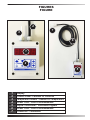
FIGURES
FIGURE
1
2
3
4
7
6
5
1
Display
2
Control Panel - Pannello Di Controllo
3
Temperature Sensor - Sensore Di Temperatura
4
Power Cord - Cavo Di Alimentazione
5
Digital Thermostat - Termostato Digitale
6
Power Cord - Cavo Di Alimentazione
7
Connector - Connettore

en
it
de
es
fr
nl
pt
da
no
sv
pl
ru
cs
hu
sl
tr
hr
lt
lv
et
ro
sk
bg
uk
bs
el
zh
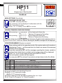
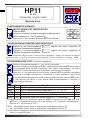
Single-level thermostat
HP11
SL 4.0
These settings refer to the operation mode of the system and must be made on
initial startup. Press - / + at the same time for at least one second: the message
C.O.S.t. will be displayed.
Press than repeatedly SET until the message regarding the chosen variable is
displayed (see table below): variable’s value and message will be displayed.
Press + or - to set a new value and then press SET to confirm.
The next system constant will then appear.
You can press SET for at least 2 seconds to exit and return to the Run Mode.
MAIN SETTINGS (Run Mode).
Example t.SEt = 25.0°
TEMPERATURE SETTING.
Press SET (key lamp flashes):
This message will be displayed in alternance with the
°Set 1 temperature value .
Press + or - to modify. Press SET to confirm.
COSt PROGRAMMING (System constants).
Handbook
*1) For more details see Operating Diagrams.
*2) tEnP =1 : °C Temperature range.
tEnP =2 : °F Temperature range.
*3) Sensor reading can be adjusted by pressing the + or - keys
*4) =0 Relay De-Energised, =1 Relay Energised.
. sseM eu l aV g n i n a eM e t oN
FF i d
°2 . 0
lai tneref f id°
1*
PnE t
1=
) F °2=,C°1= (no i t a t nese r pe re r u t a r epme T
2*
E t . dA
°0
) - r o+ (no i t ce r r ocr osnese r u t a r epme t t upn I °
3*
CO . Y r
1=
)C .O( t i uc r i CnepOr osnesf is u t a t sya l eR
4*
CS . Y r
0=
)C.S( t i uc r iCt r ohSr osnesf isu t a t sya l eR
4*
After pressing + will be displayed followed by
°Maximum Temperature Recording.
After pressing - will be displayed followed by
°Minimum Temperature Recording.
VIEWING TEMPERATURE RECORDING
Recorder values are stored in a permanent memory. To clean memory keep pushed +
keys for more than 3 seconds. Before cleaning the CLEA message will be displayed.
As it company policy to continually improve the products the Manufacturers reserve
the right to make any modifications thereto without prior notice. They cannot be held
liable for any damage due to malfunction.
07.01.13
PRESET PROGRAMS
At delivery this processor is programmed with the following (variable) settings.
To return to these settings at any time.
Power off the processor, press SET key and keep it pressed giving power on: release SET key
when on the screen boot message appears. t.SEt.= 25.0°
The COSt values are shown in COSt paragraphs.
In some start-up conditions may be useful to work in "hand" mode.
Power off the processor, push + key and keep it pressed giving power on:
HAnd message will be displayed (release now + key).
Press + (1 is displayed) and press SET to activate relay.
You can press SET key for a least two seconds to escape and return to the Run Mode.
MANUAL MODE
STATE INDICATION LAMPS
COOL ON
HEAT ON
The lights situated at the bottom of the
display show the state of the relay.
OPERATING DIAGRAM
1/2dIFF
HEAT
COOL
dIFF
t.SEt
TEMPER.
1/2dIFF
HP11
HEAT CONTACT
SX TEMP. PROBE
* Other power voltage if you required
COOL CONTACT
230V LINE *
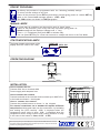
INSTALLATION
How to connect the sensors
Connect the provided sensor as shown in the diagram.
For remote connections use a standard 0.5-square millimetre
two-pole wire, taking great care over the connections, by insulating
and sealing the joins carefully. -O.C.- is displayed when the
temperature sensor wiring is open, -S.C.- is displayed when the
temperature sensor wiring is short circuit (exiting condition of relay
in this case is that setted in Cost, rY.OC - rY-SC).
How to connect the line
Connect 230V line on terminals L-N.
Protect supply with adequate fuse.
How to connect the contacts
Connect terminals on the terminal block (contacts up to 4AMP.AC1)
to the loads as shown in the diagram.

en
it
de
es
fr
nl
pt
da
no
sv
pl
ru
cs
hu
sl
tr
hr
lt
lv
et
ro
sk
bg
uk
bs
el
zh
Single-level thermostat
HP11
SL 4.0
These settings refer to the operation mode of the system and must be made on
initial startup. Press - / + at the same time for at least one second: the message
C.O.S.t. will be displayed.
Press than repeatedly SET until the message regarding the chosen variable is
displayed (see table below): variable’s value and message will be displayed.
Press + or - to set a new value and then press SET to confirm.
The next system constant will then appear.
You can press SET for at least 2 seconds to exit and return to the Run Mode.
MAIN SETTINGS (Run Mode).
Example t.SEt = 25.0°
TEMPERATURE SETTING.
Press SET (key lamp flashes):
This message will be displayed in alternance with the
°Set 1 temperature value .
Press + or - to modify. Press SET to confirm.
COSt PROGRAMMING (System constants).
Handbook
*1) For more details see Operating Diagrams.
*2) tEnP =1 : °C Temperature range.
tEnP =2 : °F Temperature range.
*3) Sensor reading can be adjusted by pressing the + or - keys
*4) =0 Relay De-Energised, =1 Relay Energised.
. sseM eu l aV g n i n a eM e t oN
FF i d
°2 . 0
lai tneref f id°
1*
PnE t
1=
) F °2=,C°1= (no i t a t nese r pe re r u t a r epme T
2*
E t . dA
°0
) - r o+ (no i t ce r r ocr osnese r u t a r epme t t upn I °
3*
CO . Y r
1=
)C .O( t i uc r i CnepOr os nesf is u t a t sya l eR
4*
CS . Y r
0=
)C.S( t i uc r iCt r ohSr osnesf isu t a t sya l eR
4*
After pressing + will be displayed followed by
°Maximum Temperature Recording.
After pressing - will be displayed followed by
°Minimum Temperature Recording.
VIEWING TEMPERATURE RECORDING
Recorder values are stored in a permanent memory. To clean memory keep pushed +
keys for more than 3 seconds. Before cleaning the CLEA message will be displayed.
As it company policy to continually improve the products the Manufacturers reserve
the right to make any modifications thereto without prior notice. They cannot be held
liable for any damage due to malfunction.
07.01.13
PRESET PROGRAMS
At delivery this processor is programmed with the following (variable) settings.
To return to these settings at any time.
Power off the processor, press SET key and keep it pressed giving power on: release SET key
when on the screen boot message appears. t.SEt.= 25.0°
The COSt values are shown in COSt paragraphs.
In some start-up conditions may be useful to work in "hand" mode.
Power off the processor, push + key and keep it pressed giving power on:
HAnd message will be displayed (release now + key).
Press + (1 is displayed) and press SET to activate relay.
You can press SET key for a least two seconds to escape and return to the Run Mode.
MANUAL MODE
STATE INDICATION LAMPS
COOL ON
HEAT ON
The lights situated at the bottom of the
display show the state of the relay.
OPERATING DIAGRAM
1/2dIFF
HEAT
COOL
dIFF
t.SEt
TEMPER.
1/2dIFF
HP11
HEAT CONTACT
SX TEMP. PROBE
* Other power voltage if you required
COOL CONTACT
230V LINE *
INSTALLATION
How to connect the sensors
Connect the provided sensor as shown in the diagram.
For remote connections use a standard 0.5-square millimetre
two-pole wire, taking great care over the connections, by insulating
and sealing the joins carefully. -O.C.- is displayed when the
temperature sensor wiring is open, -S.C.- is displayed when the
temperature sensor wiring is short circuit (exiting condition of relay
in this case is that setted in Cost, rY.OC - rY-SC).
How to connect the line
Connect 230V line on terminals L-N.
Protect supply with adequate fuse.
How to connect the contacts
Connect terminals on the terminal block (contacts up to 4AMP.AC1)
to the loads as shown in the diagram.

en
it
de
es
fr
nl
pt
da
no
sv
pl
ru
cs
hu
sl
tr
hr
lt
lv
et
ro
sk
bg
uk
bs
el
zh
HP11
FUNZIONAMENTO NORMALE
IMPOSTAZIONE SET TEMPERATURA
Premere SET:
sul visore comparirà questo messaggio in alternanza al
valore impostato di °Set Temperatura.
Agire su + o - per variarlo, premere SET a conferma.
Esempio con t.SEt = 25.0°
Manuale d'uso
SL 4.0
Termostato singolo livello
Premere contemporaneamente + / - per più di un secondo:
sul visore comparirà il messaggio C.O.S.t. : a questo punto premere SET fino a portarsi
sul messaggio della variabile interessata (vedi tabella sottoriportata): sul visore
comparirà il valore impostato di tale variabile in alternanza al messaggio.
Agire su + o - per impostare un nuovo valore, premere SET a conferma; dopodichè
comparirà la variabile successiva in alternanza al valore impostato. Agire come
precedentemente spiegato per procedere nella programmazione, premere SET per più
di due secondi per uscire in ogni istante dalla programmazione e ritornare in
Funzionamento Normale.
PROGRAMMAZIONE COST (Costanti di Impianto)
*1) Il differenziale ha azione simmetrica rispetto al t.SEt: ad esempio con un t.SEt= 20.0° e un
diFF= 0.2° il riscaldamento partirà a 19.9° per fermarsi a 20.1° (mentre il raffreddamento
partirà a 20.1° per fermarsi a 19.9°).
*2) =1 : impostando questo valore la temperatura viene rappresentata in °C.
=2 : impostando questo valore la temperatura viene rappresentata in °F.
*3) E' possibile correggere la lettura della sonda temperatura inserendo una correzione:positiva
(tasto +) o negativa (tasto - ).
VISUALIZZAZIONE TEMPERATURE REGISTRATE
Premere + : sul visore comparirà seguito dal valore registrato di
°Massima Temperatura Ambiente
I valori memorizzati vengono tenuti in memoria anche spegnendo il modulo: per azzerare la memoria
premere il tasto + per più di 3 secondi: prima di azzerarsi sul visore comparirà il messaggio CLEA.
Premere - : sul visore comparirà seguito dal valore registrato di
°Minima Temperatura Ambiente
. sseM e ro l aV o t ac i f i ng i S e t oN
FF i d
°2 . 0
elai zneref f idC°
1*
PnE t
1=
) F °2=,C°1= (a r u t a r epme teno i za t nese r ppa r i dop i T
2*
E t . dA
°0 . 0
) -o+ (a r u t a r epme tadnoseno i ze r r ocC°
3*
CO . Y r
1=
o t a t i c ce=) .C .O(a t r epaadnosnocya l e reno i z i dnoC
CS . Y r
0=
o t a t i c ces i d=) .C . S (as u i hcadnosnocya l e reno i z i dnoC
Al fine di miglioramenti futuri si riserva la facoltà di apportare variazioni a questo
prodotto senza nessun obbligo di preavviso. Il fabbricante non risponde per
eventuali danni derivanti dal cattivo funzionamento del prodotto.
07.01.13
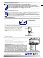
HP11
CONT. RISCALD.
SONDA TEMP. SX
* Altre tensioni a richiesta
CONT. RAFFRED.
LINEA 230V *
INSTALLAZIONE
Allacciamento sonda
Allacciare la sonda in dotazione in accordo allo schema :
per collegamenti in distanza usare del normale cavetto bipolare
da 0,5mmq, ponendo la massima attenzione alla connessione (isolare
e sigillare accuratamente le giunte). Nel caso di apertura del circuito
della sonda di temperatura sul visore comparirà il messaggio -O.C.-
per cortocircuito il messaggio -S.C.- (la condizione di eccitazione del
relay in questo caso è quella impostata in Cost, ry.OC - ry=SC).
Allacciamento linea
Allacciare la linea ai terminali L-N della morsettiera; proteggere la
linea di alimentazione con fusibile adeguato.
Allacciamento contatti
Allacciare i terminali della morsettiera (contatti fino a 4AMP.AC1) ai
carichi da comandare in accordo allo schema stabilito.
Il differenziale ha azione simmetrica rispetto al t.SEt:
ad esempio con un t.SEt= 20.0° e un diFF= 0.2° il
riscaldamento partirà a 19.9° per fermarsi a 20.1°
(mentre il raffreddamento partirà a 20.1° per fermarsi
a 19.9°).
DIAGRAMMA DI FUNZIONAMENTO
1/2dIFF
HEAT
COOL
dIFF
t.SEt
TEMPER.
1/2dIFF
FUNZIONAMENTO MANUALE
Spegnere il processore dopodichè premere + e, tenendolo sempre premuto, ridare tensione al
processore; sul visore comparirà il messaggio HAnd (a questo punto lasciare il tasto +).
Agire sul tasto + fino a far comparire sul display il messaggio 1 , dopodichè premere SET per
inserire il relay. Per uscire dalla condizione manuale premere SET per più di un secondo; il
processore ritornerà in Funzionamento Normale.
LAMPADINI DI STATO
I lampadini posizionati
sotto il visore indicano lo
stato di azionamento del
controllore:
RISCALDAMENTO ON (HEAT)
RAFFRESCAMENTO ON (COOL)
Lampadini di stato
Questo processore è preprogrammato con le seguenti impostazioni.
Per ritornare in qualsiasi istante a queste preimpostazioni procedere nel seguente modo:
spegnere il processore dopodichè premere SET e, tenendolo sempre premuto, ridare tensione;
lasciare il tasto SET quando sul visore comparirà il messaggio boot.
Dopo qualche istante il processore tornerà in Funzionamento Normale, con inserito i seguenti
parametri: t.SEt=25.0° . Il valore delle COSt è dichiarato nel paragrafo COSt.
PROGRAMMI PREIMPOSTATI

en
it
de
es
fr
nl
pt
da
no
sv
pl
ru
cs
hu
sl
tr
hr
lt
lv
et
ro
sk
bg
uk
bs
el
zh
HP11
FUNZIONAMENTO NORMALE
IMPOSTAZIONE SET TEMPERATURA
Premere SET:
sul visore comparirà questo messaggio in alternanza al
valore impostato di °Set Temperatura.
Agire su + o - per variarlo, premere SET a conferma.
Esempio con t.SEt = 25.0°
Manuale d'uso
SL 4.0
Termostato singolo livello
Premere contemporaneamente + / - per più di un secondo:
sul visore comparirà il messaggio C.O.S.t. : a questo punto premere SET fino a portarsi
sul messaggio della variabile interessata (vedi tabella sottoriportata): sul visore
comparirà il valore impostato di tale variabile in alternanza al messaggio.
Agire su + o - per impostare un nuovo valore, premere SET a conferma; dopodichè
comparirà la variabile successiva in alternanza al valore impostato. Agire come
precedentemente spiegato per procedere nella programmazione, premere SET per più
di due secondi per uscire in ogni istante dalla programmazione e ritornare in
Funzionamento Normale.
PROGRAMMAZIONE COST (Costanti di Impianto)
*1) Il differenziale ha azione simmetrica rispetto al t.SEt: ad esempio con un t.SEt= 20.0° e un
diFF= 0.2° il riscaldamento partirà a 19.9° per fermarsi a 20.1° (mentre il raffreddamento
partirà a 20.1° per fermarsi a 19.9°).
*2) =1 : impostando questo valore la temperatura viene rappresentata in °C.
=2 : impostando questo valore la temperatura viene rappresentata in °F.
*3) E' possibile correggere la lettura della sonda temperatura inserendo una correzione:positiva
(tasto +) o negativa (tasto - ).
VISUALIZZAZIONE TEMPERATURE REGISTRATE
Premere + : sul visore comparirà seguito dal valore registrato di
°Massima Temperatura Ambiente
I valori memorizzati vengono tenuti in memoria anche spegnendo il modulo: per azzerare la memoria
premere il tasto + per più di 3 secondi: prima di azzerarsi sul visore comparirà il messaggio CLEA.
Premere - : sul visore comparirà seguito dal valore registrato di
°Minima Temperatura Ambiente
. sseM e ro l aV o t ac i f i ng i S e t oN
FF i d
°2 . 0
elai zneref f idC°
1*
PnE t
1=
) F °2=,C°1= (a r u t a r epme teno i za t nese r ppa r i dop i T
2*
E t . dA
°0 . 0
) -o+ (a r u t a r epme tadnoseno i ze r r ocC°
3*
CO . Y r
1=
o t a t i c ce=) .C .O(a t r epaadnosnocya l e reno i z i dnoC
CS . Y r
0=
o t a t i c ces i d=) .C . S (as u i hcadnosnocya l e reno i z i dnoC
Al fine di miglioramenti futuri si riserva la facoltà di apportare variazioni a questo
prodotto senza nessun obbligo di preavviso. Il fabbricante non risponde per
eventuali danni derivanti dal cattivo funzionamento del prodotto.
07.01.13
HP11
CONT. RISCALD.
SONDA TEMP. SX
* Altre tensioni a richiesta
CONT. RAFFRED.
LINEA 230V *
INSTALLAZIONE
Allacciamento sonda
Allacciare la sonda in dotazione in accordo allo schema :
per collegamenti in distanza usare del normale cavetto bipolare
da 0,5mmq, ponendo la massima attenzione alla connessione (isolare
e sigillare accuratamente le giunte). Nel caso di apertura del circuito
della sonda di temperatura sul visore comparirà il messaggio -O.C.-
per cortocircuito il messaggio -S.C.- (la condizione di eccitazione del
relay in questo caso è quella impostata in Cost, ry.OC - ry=SC).
Allacciamento linea
Allacciare la linea ai terminali L-N della morsettiera; proteggere la
linea di alimentazione con fusibile adeguato.
Allacciamento contatti
Allacciare i terminali della morsettiera (contatti fino a 4AMP.AC1) ai
carichi da comandare in accordo allo schema stabilito.
Il differenziale ha azione simmetrica rispetto al t.SEt:
ad esempio con un t.SEt= 20.0° e un diFF= 0.2° il
riscaldamento partirà a 19.9° per fermarsi a 20.1°
(mentre il raffreddamento partirà a 20.1° per fermarsi
a 19.9°).
DIAGRAMMA DI FUNZIONAMENTO
1/2dIFF
HEAT
COOL
dIFF
t.SEt
TEMPER.
1/2dIFF
FUNZIONAMENTO MANUALE
Spegnere il processore dopodichè premere + e, tenendolo sempre premuto, ridare tensione al
processore; sul visore comparirà il messaggio HAnd (a questo punto lasciare il tasto +).
Agire sul tasto + fino a far comparire sul display il messaggio 1 , dopodichè premere SET per
inserire il relay. Per uscire dalla condizione manuale premere SET per più di un secondo; il
processore ritornerà in Funzionamento Normale.
LAMPADINI DI STATO
I lampadini posizionati
sotto il visore indicano lo
stato di azionamento del
controllore:
RISCALDAMENTO ON (HEAT)
RAFFRESCAMENTO ON (COOL)
Lampadini di stato
Questo processore è preprogrammato con le seguenti impostazioni.
Per ritornare in qualsiasi istante a queste preimpostazioni procedere nel seguente modo:
spegnere il processore dopodichè premere SET e, tenendolo sempre premuto, ridare tensione;
lasciare il tasto SET quando sul visore comparirà il messaggio boot.
Dopo qualche istante il processore tornerà in Funzionamento Normale, con inserito i seguenti
parametri: t.SEt=25.0° . Il valore delle COSt è dichiarato nel paragrafo COSt.
PROGRAMMI PREIMPOSTATI

MCS Italy S.p.A.
Via Gardesana 11, -37010-
Pastrengo (VR), Italy
MCS Central Europe Sp. z o.o.
ul. Magazynowa 5A,
62-023 Gądki, Poland
MCS Russia LLC
ul. Transportnaya - 22 ownership 2,
142802, STUPINO, Moscow region, Russia
MCS China LTD
Unit A1, No. 1515, Jinshao Rd.,
Baoshan Industrial Zone,
Shanghai, 200949, China
4150.116 Edition 15
-
 1
1
-
 2
2
-
 3
3
-
 4
4
-
 5
5
-
 6
6
-
 7
7
-
 8
8


Master HP11 Manuale del proprietario
- Tipo
- Manuale del proprietario
- Questo manuale è adatto anche per
in altre lingue
- English: Master HP11 Owner's manual
Altri documenti
-
Extraflame Wireless thermostat Manuale del proprietario
-
-
Eton Grundig S450DLX (S 450) Manuale utente
-
TFA Digital Alarm Clock with Luminous Digits TIME BLOCK Manuale del proprietario
-
-
-
Carel mchiller compact Manuale utente
-
Renkforce 1369489 Manuale del proprietario
-
-