
LiveCore™ unit
(V04.02.75)
References:
ASC4806-4K-PL, ASC3204-4K-PL, ASC1602-4K, SMX12x4, NXT1604-4K,
NXT0802-4K, ASC48LE-4K, ASC32LE-4K, ASC16LE-4K, LOE048-4K-PL,
LOE032-4K, LOE016-4K
USER MANUAL


THANK YOU
1. TRADEMARKS
3. TERMS AND DEFINITIONS
2. INTRODUCTION
4. HARDWARE SPECIFICATIONS
4.1
4.1.1 English
4.1.2 French
4.1.3 Italian
4.1.4 German
4.1.5 Spanish
4.5.1 Signal descripons
4.5.2 Supported video formats
4.5.3 Computer formats
4.5.4 Input Computer formats
4.5.5 Output Computer formats
4.7.1 Standard output
4.7.2 Monitoring output
4.8.1 Serial interface
4.8.2 LAN interface
4.8.3 Protocol
4.8.4 IP address
4.8.5 USB host interface
4.8.6 Compliance
4.9.1 Ascender 48 - 4K - PL
4.9.2 Ascender 32 - 4K - PL
4.9.3 Ascender 16 - 4K
4.9.4 SmartMatriX Ultra
4.9.5 NeXtage 16 - 4K
4.9.6 NeXtage 08 - 4K
4.9.7 LiveCore™ Output Expander - Ref. LOE048-4K-PL, LOE032-4K, LOE016-4K
6
7
6
8
8
13
14
17
13
14
20
21
23
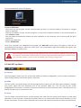
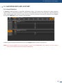
By following these simple steps you will be able to obtain the most from your powerful LiveCore™ unit and
its many features related to the version 04.02.20.
4.10 HDCP management
4.10.1 Input HDCP detecon
4.10.2 Output HDCP detecon
30
Also available and supported :
- Ascender LE 48 - 4K
- Ascender LE 32 - 4K
- Ascender LE 16 - 4K

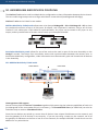
5. CONNECTING A LIVECORE™ UNIT
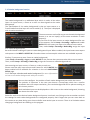
6. CONTROLLING A LIVECORE™ UNIT
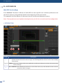
7. OPERATING A LIVECORE™ UNIT FROM THE WEB RCS
5.1
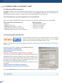
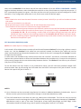
6.1 Web-based RCS requirement
7.1
6.2
7.2
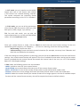
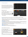
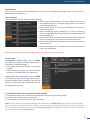
6.3 Web RCS top Menu
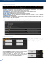
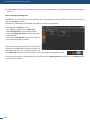
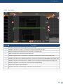
7.3 Setup
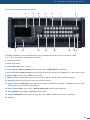
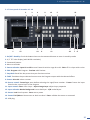
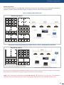
5.1.1 Rear panel of 4RU LiveCore™ unit
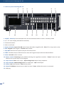
5.1.2 Rear panel of 4RU
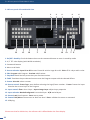
5.1.3 Rear panel of 3RU
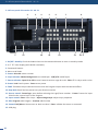
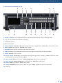
5.1.4 Rear panel of a LiveCore™ Output Expander
5.1.5 Front panel of Ascender 48 - 4K - PL
5.1.6 Front panel of Ascender 32 - 4K - PL
5.1.7 Front panel of Ascender 16 - 4K
5.1.8 Front panel of SmartMatriX Ultra
5.1.9 Front panel of NeXtage 16 - 4K
5.1.10 Front panel of NeXtage 08 - 4K
5.1.11 Front panel of a LiveCore™ Output Expander
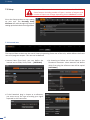
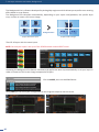
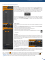
6.3.1 Setup
6.3.2 Edit
6.3.3 Live
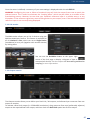
7.2.1 Single device conguraon
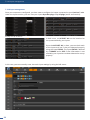
7.3.1 Internal rate
7.3.2 Link secon
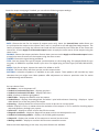
7.3.3 Outputs secon
7.3.4 Screens
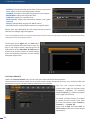
7.3.5 Inputs secon
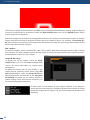
7.3.6 Logos
7.3.7 Nave background secon
7.3.8 The Miscellaneous secon
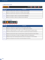
7.3.9 Output management
7.3.10 Input management
7.3.11 Library management
7.3.12 Logo management
7.3.13 Monitoring management
7.3.14 Blending management
7.3.15 Services management (update)
7.3.16 Control management
31
45
47
31
45
47
45
47
46
49
4.10.3 Keys’ checking
4.10.4 Output management
4.10.5 HDCP Classicaon
4.10.6 Status
Also available and supported :
- Ascender LE 48 - 4K
- Ascender LE 32 - 4K
- Ascender LE 16 - 4K

8. OPERATING THROUGH THE FRONT PANEL
12. APPLICATIONS NOTE AND TIPS
11. MAINTENANCE AND SUPPORT
9. ADDITIONAL REMOTE CONTROL SYSTEMS
10. ASSEMBLING AND DEVICES COUPLING
13. WARRANTY
14. CONTACT INFORMATION
15. APPENDICES
8.1 Front panel
12.1 HDCP
13.1
13.2
13.3
11.1
10.1
8.2 Menu tree
11.2
10.2
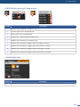
7.4 Edit
7.5 Live
7.6
7.4.1 Layer management
7.4.2 Layer properes
7.4.3 Layer sengs
7.4.4 Layer selecon and nave background
7.4.5 Preset load and save management
7.4.6 Logos and Frames management
7.4.7 Inputs management
7.4.8 Monitoring management
7.4.9 Condence management
7.6.1 Edit page
7.6.2 Memories and AUTOSCALE with Perspecve Layers
8.1.1 Front panel update
8.1.2 LCD screen
8.1.3 Front panel buons
100
120
118
114
115
121
122
123
100
120
121
121
121
118
115
103
119
116
79
94
98

6
1. Trademarks
1. TRADEMARKS
2. INTRODUCTION
The terms HDMI, HDMI High-Denion Mulmedia Interface and the HDMI Logo are trademarks or registered
trademarks of HDMI Licensing LLC in the United States and other countries.
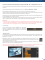
Thank you for choosing an Analog Way LiveCore™ unit. Before you start seng up your LiveCore™ unit for
the rst me, please read through all of the documentaon to become familiar with its powerful features.
A LiveCore™ unit can be used in several conguraons, which results in a versale video producon tool for
live event staging and xed installaon applicaons.
hp://www.analogway.com/en/support/product-registraon/

7
3. Terms and denions
3. TERMS AND DEFINITIONS
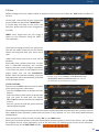
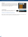
BACKGROUND: a “Background” is a source, typically originang from a computer. A LiveCore™ unit enables
you to work with live or sll (Frame) background sources — visually in back of all other sources.
LAYER: a “Layer” is an image display element (such as a PIP window, Key, Logo or Background) that has a
visual priority — either in front (or in back) of another layer. Depending on the LiveCore™ unit type, up to 6
independent true-seamless scaled layers are available.
PIP: a “PIP” (Picture In Picture) is a picture, typically of reduced size, which is posioned over another
background image or other PIPs. PIPs can be reposioned, reduced, enlarged and displayed with borders.
PIPs can overlap, depending on their visual priority. A LiveCore™ unit oers various slides, wipes, and fades
for dynamic PIP entrances and exits. A “ying” PIP is also possible using vercal, horizontal, diagonal, or
curved movement. A PIP is considered a layer.
FRAME: a “Frame” is a full screen image which is selected from one of the sll Frames loaded on the LiveCore™
unit. Frames are imported from a computer through the Web RCS.
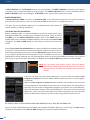
LOGO: a “Logo” is an image imported from a computer, through the Web RCS. It can be keyed, resized and
displayed on a layer. A LiveCore™ unit can also resize the logo to be displayed in any size on the screen by
resizing and place the related layer.
KEYING: “Key” is an electronic process whereby a video image is electronically superimposed over another
source or background, by dynamically removing a poron of the rst image. For example, removing all content
of a certain color (such as green or blue) is called a cung out either a color (Chroma Key,) and removing
content based onor its brightness or luminance levels is called a (Luma Key). Keys are typically used for tles,
Logos and special eects. A LiveCore™ unit allows you to key use a live source with Luma or Chroma key
eects with green or blue background and to display key it over any other source or sources.
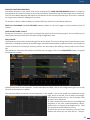
SCREEN: A “Screen” is a desnaon where the picture will be displayed. For example, it could be a single
display or a projecon surface which can be composed of one or several outputs. Each screen might composed
with of one or several layers.
SEAMLESS: Clean transion with no glitch or loss of sync while switching between two sources. For example,
fading through black to another source is a seamless transion.
TRUE SEAMLESS: Clean seamless transions with no glitch or freeze between two sources. For example,
crossfading from source to source is a true seamless transion.
WEB RCS: Web browser based Remote Control Soware used to control, set up, and operate the device.
SOFT EDGE: So Edge blending technology is used to compensate for the overlap or covering area when two
(or more) video projectors are combined to display a connuous content across one screen. The resulng
image will appear as though it were a single unied picture.
HARD EDGE: Hard Edge technology is used to display connuous content using to several outputs without
any overlap or covering area. The outputs are “side by side”, they don’t overlap or share pixel informaon.
(Opposed to So Edge where some parts of the image are simultaneously on several displays.)
CONFIDENCE MONITOR: Condence monitoring consists on using an output to display a specic content
such as another screen, input or combinaon there-of. You can display one of the main outputs or Preview
output content. For example, you might use the condence monitor to show both the presenter’s laptop
input as well as the Program screen on a single display.

8
4.1 Safety instrucons
4. HARDWARE SPECIFICATIONS
All of the safety and operang instrucons should be read before the product is operated and should
be maintained for further reference. Please follow all of the warnings on this product and its operang
instrucons.
• WARNING: To prevent the risk of electric shock and re, do not expose this device to rain, humidity or
intense heat sources (such as heaters and direct sunlight). Slots and openings in the device are provided for
venlaon and to avoid overheang. Make sure the device is never placed near a texle surface that could
block the openings. Also keep away from excessive dust, vibraons and shocks.
• POWER: Only use the power supply indicated on the device of the power source. Devices equipped with
a grounding plug should only be used with a grounding type outlet. In no way should this grounding be
modied, avoided or suppressed. Connecon of equipment to main supply must be aer branch circuit
breaker of the building installaon.
• POWER CORD: The device is equipped with a detachable power cord, to remove mains disconnect it at
appliance coupler.
The power cord constutes the only mean to completely disconnect the equipment from the main
power.
- The equipment connected to the network must have a release system easily accessible and located
outside the unit.
- Unplug the power cord; do not pull on the power cord but always on the plug itself.
- The outlet should always be near the device and easily accessible.
- Power supply cords should be routed so that they are not likely to be walked on or pinched by items
placed upon or against them.
If the power supply cord is damaged, unplug the device. Using the device with a damaged power supply cord
may expose your device to electric shocks or other hazards. Verify the condion of the power supply cords
once in a while. Contact your dealer or service center for replacement if damaged.
• CONNECTIONS: All inputs and outputs (except for the power input) are Safety Extra Low Voltage (SELV)
circuits as dened in UL/IEC 60950-1.
• SERVICING: Do not aempt to service this product yourself by opening or removing covers and screws
since it may expose your device to electric shocks or other hazards. Refer all problems to qualied service
personnel.
• OPENINGS: Never push objects of any kind into this product through the openings. If liquids have been
spilled or objects have fallen into the device, unplug it immediately and have it checked by a qualied
technician.
4.1

9
4.1 Safety instrucons
An de mieux comprendre le fonconnement de cet appareil nous vous conseillons de bien lire toutes les
consignes de sécurité et de fonconnement avant ulisaon. Conservez les instrucons de sécurité et de
fonconnement an de pouvoir les consulter ultérieurement. Respectez toutes les consignes marquées dans la
documentaon, sur le produit et sur ce document.
• ATTENTION : An de prévenir tout risque de choc électrique et d’incendie, ne pas exposer cet appareil à la
pluie, à l’humidité ou à des sources de chaleur intense.
• INSTALLATION : Veillez à assurer une circulaon d’air susante pour éviter toute surchaue à l’intérieur de
l’appareil. Ne placez pas l’appareil sur ou à proximité d’une surface texle suscepble d’obstruer les orices de
venlaon. N’installez pas l’appareil à proximité de sources de chaleur comme un radiateur ou une poche d’air
chaud, ni dans un endroit exposé au rayonnement solaire direct, à des poussières excessives, à des vibraons
ou à des chocs mécaniques. Ceci pourrait provoquer un mauvais fonconnement et un accident.
• ALIMENTATION : Ne faire fonconner l’appareil qu’avec la source d’alimentaon indiquée sur l’appareil.
Les appareils doivent être obligatoirement connectés sur une source équipée d’une mise à la terre ecace.
En aucun cas cee liaison de terre ne devra être modiée, contournée ou supprimée. Raccordement des
équipements à l’alimentaon principale doit être postérieur au disjoncteur de branchement de l’installaon
électrique du bâment.
• CORDON D’ALIMENTATION : Les appareils sont équipés d’un cordon d’alimentaon détachable, la mise
hors tension se fait en débranchant ce cordon de l’appareil.
Le cordon d’alimentaon constue le seul moyen de débrancher l’appareil totalement de
l’alimentaon secteur. Pour être certain que l’appareil n’est plus alimenté, ce cordon doit être
débranché de la prise murale.
Appliquer les consignes suivantes :
- Le matériel relié à demeure au réseau, doit avoir un disposif de seconnement facilement accessible
qui doit être incorporé à l’extérieur de l’appareil.
- Débrancher le cordon d’alimentaon de la prise murale si vous prévoyez de ne pas uliser l’appareil
pendant quelques jours ou plus.
- Pour débrancher le cordon, rez-le par la che. Ne rez jamais sur le cordon proprement dit.
- La prise d’alimentaon doit se trouver à proximité de l’appareil et être aisément accessible.
- Ne laissez pas tomber le cordon d’alimentaon et ne posez pas d’objets lourds dessus.
Si le cordon d’alimentaon est endommagé, débranchez-le immédiatement de la prise murale. Il est
dangereux de faire fonconner un appareil avec un cordon endommagé ; un câble abîmé peut provoquer un
risque d’incendie ou un choc électrique. Vériez le câble d’alimentaon de temps en temps. Contactez votre
revendeur ou le service après-vente pour un remplacement.
• CONNEXIONS : Toutes les entrées et sores (exceptée l’entrée d’alimentaon) sont des circuits de très
basse tension de sécurité (TBTS) tels que dénis dans UL / IEC 60950-1.
• RÉPARATION ET MAINTENANCE : L’ulisateur ne doit en aucun cas essayer de procéder aux opéraons de
dépannage, car l’ouverture des appareils par retrait des capots ou de toutes autres pièces constuant les
boîers ainsi que le dévissage des vis apparentes à l’extérieur, risquent d’exposer l’ulisateur à des chocs
électriques ou autres dangers. Contactez le service après-vente, votre revendeur ou adressez-vous à un
personnel qualié uniquement.
• OUVERTURES ET ORIFICES : Les appareils peuvent comporter des ouvertures (aéraon, fentes, etc...),
veuillez ne jamais y introduire d’objets et ne jamais obstruer ses ouvertures. Si un liquide ou un objet
pénètre à l’intérieur de l’appareil, débranchez immédiatement l’appareil et faites-le contrôler par un
personnel qualié avant de le remere en service.

10
4.1 Safety instrucons
Allo scopo di capire meglio il funzionamento di questa apparecchiatura vi consigliamo di leggere bene
tu i consigli di sicurezza e di funzionamento prima dell’ulizzo. Conservare le istruzioni di sicurezza e di
funzionamento al ne di poterle consultare ulteriormente. Seguire tu i consigli indica su questo manuale
e sull’apparecchiatura.
• ATTENZIONE: Al ne di prevenire qualsiasi rischio di shock elerico e d’incendio, non esporre l’apparecchiatura
a pioggia, umidità e a sorgen di eccessivo calore.
• INSTALLAZIONE: Assicuratevi che vi sia una suciente circolazione d’aria per evitare qualsiasi
surriscaldamento all’interno dell’apparecchiatura. Non collocare l’apparecchiatura in prossimità o su
superci tessili suscebili di ostruire il funzionamento della venlazione. Non installate l’apparecchiatura
in prossimità di sorgen di calore come un radiatore o una fuoruscita d’aria calda, né in un posto esposto
direamente ai raggi del sole, a polvere eccessiva, a vibrazioni o a shock meccanici. Ció potrebbe provocare
un erroneo funzionamento e un incidente.
• ALIMENTAZIONE: Far funzionare l’apparecchiatura solo con la sorgente d’alimentazione indicata
sull’apparecchiatura. Le apparecchiature queste devono essere obbligatoriamente collegate su una sorgente
fornita di una eciente messa a terra. In nessun caso questo collegamento potrà essere modicato, sostuito
o eliminato. Connessione delle apparecchiature alla rete elerica deve essere successiva interruore di
circuito dell’impianto dell’edicio
• CAVO DI ALIMENTAZIONE: Il disposivo è dotato di un cavo di alimentazione removibile, per rimuovere
alimentazione scollegarlo dalla Presa.
il cavo di alimentazione è il solo modo di disconneere l’apparecchio dell’alimentazione. Per
assicurarsi che totalemente l’apparecchio non è più collegato, il cavo deve essere disconesso della presa
murale.
- Il materiale collegato a residenza alla rete, deve avere un disposivo di sezionamento facile da
raggiongere eche deve essere inserito all’esterno del apparecchio.
- Disconneere l’apparecchiatura dalla presa murale se si prevede di non ulizzarla per qualche giorno.
- Per disconneere il cavo rare facendo forza sul conneore.
- La presa d’alimentazione deve trovarsi in prossimità dell’apparecchiatura ed essere facilmente
accessibile.
- Non far cadere il cavo di alimentazione né appoggiarci sopra degli ogge pesan. Se il cavo di
alimentazione é danneggiato, spegnere immediatamente l’apparecchiatura.
E’ pericoloso far funzionare questa apparecchiatura con un cavo di alimentazione danneggiato, un cavo
graato puó provocare un rischio di incendio o uno shock elerico. Vericare il cavo di alimentazione spesso.
Contaare il vostro rivenditore o il servizio assistenza per una sostuzione.
• CONNESSIONE: Tu gli ingressi e le uscite (tranne che per la potenza in ingresso) sono bassissima tensione
di sicurezza (SELV) circui deni UL / IEC 60950-1.
• RIPARAZIONI E ASSISTENZA: L’ulizzatore non deve in nessun caso cercare di riparare l’apparecchiatura,
poiché con l’apertura del coperchio metallico o di qualsiasi altro pezzo costuente la scatola metallica,
nonché svitare le vi che appaiono esteriormente, poiché ció puó provocare all’ulizzatore un rischio di
shock elerico o altri rischi.
• APERTURE DI VENTILAZIONE: Le apparecchiature possono comportare delle aperture di venlazione, si
prega di non introdurre mai ogge o ostruire le sue fessure. Se un liquido o un oggeo penetra all’interno
dell’apparecchiatura, disconneerla e farla controllare da personale qualicato prima di rimeerla in
servizio.
4.1.3 Italian

11
4.1 Safety instrucons
Um den Betrieb dieses Geräts zu verstehen, raten wir Ihnen vor der Inbetriebnahme alle Sicherheits und
Betriebsanweisungen genau zu lesen. Diese Sicherheits- und Betriebsanweisungen für einen späteren Gebrauch
sicher auewahren. Alle in den Unterlagen, an dem Gerät und hier angegebenen Sicherheitsanweisungen
einhalten.
• ACHTUNG: um jegliches Risiko eines Stromschlags oder Feuers zu vermeiden, das Gerät nicht Regen,
Feuchgkeit oder intensiven Wärmequellen aussetzen.
• EINBAU: Eine ausreichende Luzufuhr sicherstellen, um jegliche Überhitzung im Gerät zu vermeiden. Das
Gerät nicht auf und in Nähe von Texloberächen, die Belüungsönungen verschließen können, aufstellen.
Das Gerät nicht in Nähe von Wärmequellen, wie z.B. Heizkörper oder Warmlukappe, aufstellen und es
nicht dem direkten Sonnenlicht, übermäßigem Staub, Vibraonen oder mechanischen Stößen aussetzen.
Dies kann zu Betriebsstörungen und Unfällen führen.
• STROMVERSORGUNG: Das Gerät nur mit der auf dem Gerät bezeichnete Stromquelle betreiben. Gerät mit
geerdeter Hauptstromversorgung muss an eine Stromquelle mit ezienter Erdung angeschlossen werden.
Diese Erdung darf auf keinen Fall geändert, umgangen oder enernt werden. Anschluss von Geräten ans
Stromnetz muss nach Abzweigschalter des Gebäudes Installaon
• NETZKABEL: Das Gerät ist mit einem lösbaren Netzkabel ausgestaet ; um es völlig vom Netz zu trennen,
ziehen Sie bie das Netzkabel aus der Kaltgerätebuchse.
Das Netzkabel stellt die einzige Möglichkeit dar, das Gerät vollständig vom Netzanschluss zu trennen.
Um sicherzustellen, dass das Gerät nicht mehr versorgt wird, muss dieses Kabel aus der Netzsteckdose
ausgesteckt werden.
- Wenn Geräte dauerha am Netz bleiben, müssen sie über eine leicht zugängliche Trennvorrichtung
verfügen, die außen am Gerät angebracht sein muss.
- Das Kabel miels dem Stecker herausziehen. Niemals am Stromkabel selbst ziehen.
- Die Steckdose muß sich in der Nähe des Geräts benden und leicht zugänglich sein.
- Das Stromkabel nicht fallen lassen und keine schweren Gegenstände auf es stellen.
Wenn das Stromkabel beschädigt ist, das Gerät sofort abschalten. Es ist gefährlich das Gerät mit einem
beschädigten Stromkabel zu betreiben; ein abgenutztes Kabel kann zu einem Feuer oder Stromschlag
führen. Das Stromkabel regelmäßig untersuchen. Für den Ersatz, wenden Sie sich an Ihren Verkäufer oder
Kundendienststelle.
• ANSCHLÜSSE: Alle Eingänge und Ausgänge (mit Ausnahme der Stromversorgung) sind Safety Extra Low
Voltage (SELV) Schaltungen wie in UL / IEC 60950-1 deniert.
• REPARATUR UND WARTUNG: Der Benutzer darf keinesfalls versuchen das Gerät selbst zu reparieren, die
Önung des Geräts durch Abnahme der Abdeckhaube oder jeglichen anderen Teils des Gehäusessowie die
Enernung von außen sichtbaren Schrauben zu Stromschlägen oder anderen Gefahren für den Benutzer
führen kann. Wenden Sie sich an Ihren Verkäufer, Ihre Kundendienststelle oder an qualizierte Fachkräe.
• ÖFFNUNGEN UND MUNDUNGEN: Die Geräte können über Önungen verfügen (Belüung, Schlitze, usw.).
Niemals Gegenstände in die Önungen einführen oder die Önungen verschließen. Wenn eine Flüssigkeit
oder ein Gegenstand in das Gerät gelangt, den Stecker herausziehen und es vor einer neuen Inbetriebnahme
von qualiziertem Fachpersonal überprüfen lassen.
4.1.4 German

12
4.1 Safety instrucons
Para comprender mejor el funcionamiento de este aparato, le recomendamos que le acuidadosamente todas
las consignas de seguridad y de funcionamiento del aparato antes de usarlo. Conserve las instrucciones de
seguridad y de funcionamiento para que pueda consultarlas posteriormente. Respete todas las consignas
indicadas en la documentación, relacionadas con el producto y este documento.
• CUIDADO: Para prevenir cualquier riesgo de choque eléctrico y de incendio, no exponga este aparato a la
lluvia, a la humedad ni a fuentes de calorintensas.
• INSTALACIÓN: Cerciórese de que haya una circulación de aire suciente para evitar cualquier
sobrecalentamiento al interior del aparato. No coloque el aparato cerca ni sobre una supercie texl que
pudiera obstruir los oricios de venlación. No instale el aparato cerca de fuentes de calor como radiador o
boca de aire caliente, ni en un lugar expuesto a los rayos solares directos o al polvo excesivo, a las vibraciones
o a los choques mecánicos. Esto podría provocar su mal funcionamiento o un accidente.
• ALIMENTACIÓN: Ponga a funcionar el aparato únicamente con la fuente de alimentación que se indica en
el aparato. Los aparatos deben estar conectados obligatoriamente a una fuente equipada con una puesta
a erra ecaz. Por ningún movo este enlace de erra deberá ser modicado, cambiado o suprimido.
Conexión del equipo a la red eléctrica debe ser posterior del interruptor de circuitos derivados de la
instalación del edicio
• CABLE DE CORRIENTE: El equipo se suministra con un cable de corriente si desconectamos el cable
dejamos al equipo sin alimentación.
Atención: El cable de alimentación constuye el único medio de desconectar el aparato totalmente de la
red eléctrica. Para estar seguro de que el aparato no está más alimentado, este cable debe de ser
desconectado de la toma de corriente.
Aplicar las siguientes consignas:
- El material conectado a residencia a la red informáca, debe de tener un disposivo de seccionamiento
fácilmente accesible que debe de ser incorporado al exterior del aparato.
- Desconectar el aparato del enchufe mural si no piensa ulizarlo durante varios días.
- Para desconectar el cable, re de la clavija. No re nunca del cable propiamente dicho.
- El enchufe de alimentación debe estar cerca del aparato y ser de fácil acceso.
- No deje caer el cable de alimentación ni coloque objetos pesados encima de él.
Si el cable de alimentación sufriera algún daño, ponga el aparato inmediatamente fuera de tensión. Es
peligroso hacer funcionar este aparato con un cable averiado, ya que un cable dañado puede provocar un
incendio o un choque eléctrico. Verique el estado del cable de alimentación de vez en cuando. Póngase en
contacto con su distribuidor o con el servicio de posventa si necesita cambiarlo.
• CONEXIONES: Todas las entradas y salidas (a excepción de la entrada de alimentación) son de tensión extra
baja de seguridad (SELV) circuitos denidos en UL / IEC 60950-1.
• REPARACIÓN Y MANTENIMIENTO: Por ningún movo, el usuario deberá tratar de efectuar operaciones
de reparación, ya que si abre los aparatos rerando el capó o cualquier otra pieza que forma parte de las
cajas o si destornilla los tornillos aparentes exteriores, existe el riesgo de producirse una explosión,choques
eléctricos o cualquier otro incidente. Contacte el servicio de posventa, a su distribuidor o dirigirse con
personal cualicado únicamente.
• ABERTURAS Y ORIFICIOS: Los aparatos pueden contener aberturas (aireación, ranuras, etc.). Nointroduzca
allí ningún objeto ni obstruya nunca estas aberturas. Si un líquido o un objeto penetra al interior del aparato,
desconéctelo y hágalo revisar por personal cualicado antes de ponerlo nuevamente en servicio.

13
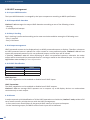
4.2 Unpacking and inspecon
• 1 x LiveCore™ unit
• 1 x Power supply cord
• 1 x Ethernet cross cable (for device control)
• 1 x Web-based Remote Control Soware included and hosted on the device
• 1 x Rack mount kit
• 1 x User manual (PDF version)*
• 1 x Quick start guide*
* User manual and Quick start guide are also available on www.analogway.com
Before racking and plugging any inputs and outputs, it is advised to power on the unit. Should you encounter
any issue, you must contact immediately your local distributor or dealer, or closest Analog Way technical
support oces (see chapter: 14. Contact informaon).
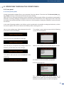
LiveCore™ unit can be used directly on a table; the unit is equipped with 4 handy an-
slip rubber feet.
LiveCore™ unit is compable with a 19” enclosure. Please follow the instrucons below to
install the device in a 19” rack.
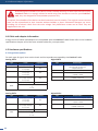
CAUTION: a 4U LiveCore™ unit weighs 42.77LBS (19,4Kg) and 3U weighs 30.86LBS (14Kg). Please provide
appropriate support to the frame during installaon. First, place ears on each side of the device (ref: 180469)
Place the device in your rack. Aach the device to the rack by using 2 screws through the ears (screws not
included).
Addional support, such as the rear rack support or slide rails, is required. LiveCore™ unit is equipped with
threaded holes designed for compability with a rear rack mount such as ref. 180489. Use the holes in the
rear support arm to adjust the length of the rear rack support arm in order to reach the rear rack rail when
installed in the rack. Use four M4x10mm screws in the countersunk holes in the rear support bar on both
sides of the unit.
A lacing bar is provided with the rack mount kit (ref: 180489). Install it with the M4x10 screws according to
your cables posion.
Connect all of the cables to the device and aach them to the lacing bar with the help of e wraps.
IMPORTANT:
- The openings in the front and rear panels of the device are for cooling. Air ows from front to back. Do not
cover these openings to avoid cung air circulaon.
- The maximum ambient operang temperature should not exceed 40°C (104°F).
- The rack and all mounted equipment in it must be reliably grounded according to naonal and/or local
electrical standards.
4.2
4.3
CAUTION!
Mounng using only the front rack ears is sucient for xed installaons. Addional support, such as the rear rack support or
slide rails, is required for mobile applicaons, and recommended for all.

14
4.4 Cable and adaptor informaon
A large choice of cables and adaptors are compable with the LiveCore™ unit. Please refer to the hardware
specicaons chapter to nd the most suitable cables for your operaons.
For each type of signal, here are the levels and the impedance accepted by the LiveCore™ unit.
4.4
4.5
Type Levels Impedance
Composite 0,7 Vpp + 0,3 Vpp 75 Ω
S. Video Y = 0,7 Vpp + 0,3 Vpp
C = 0,7 Vpp
75 Ω
YUV Y = 0,7 Vpp + 0,3 Vpp
U = 0,7 Vpp
V = 0,7 Vpp
75 Ω
RGsB R = 0,7 Vpp
G = 0,7 Vpp + 0,3 Vpp
B = 0,7 Vpp
75 Ω
RGBS
R, G, B = 0,7 Vpp R, G, B = 75 Ω
S = 0,3 Vpp 75 Ω
or
S = TTL
Type Levels Impedance
YUV Y = 0,7 Vpp + 0,3 Vpp
U = 0,7 Vpp
V = 0,7 Vpp
75 Ω
RGsB R = 0,7 Vpp
G = 0,7 Vpp + 0,3 Vpp
B = 0,7 Vpp
75 Ω
RGBS
R, G, B = 0,7 Vpp R, G, B = 75 Ω
S = 0,3 Vpp 75 Ω
or
S = TTL
Type
SD-SDI YUV - 10 bits – 4.2.2 - 270 Mb/s
No payload ID management
Only A-level type
DVI RGB ou YUV – 8 bits – 4.4.4 – 16/235 - TMDS
HDMI RGB or YUV – 10 bits – 4.4.4 or 4.2.2
– 16/235 – TMDS
DisplayPort RGB or YUV – 10 bits – 4.4.4 or 4.2.2
– 16/235 – Main Link
Type
DVI RGB or YUV – 8 bits – 4.4.4 – 16/235 - TMDS
HDMI RGB or YUV – 10 bits – 4.4.4 or 4.2.2
– 16/235 – TMDS
DisplayPort RGB or YUV – 10 bits – 4.4.4 or 4.2.2
– 16/235 – Main Link
Analog SDTV
Analog EDTV
Digital SDTV
Digital EDTV
Dismantling front handles of the device could invalidate warranty on aer-sales services of your
LiveCore™ unit. It is strongly advised to avoid using front handles as rests for your LiveCore™
unit, they are designed for manipulaon purposes only.
If required, front handles of the device can be dismantled, but with cauon. The original screws removed
must not be reintroduced to their locaon without handles in place. Substanal damages can occur,
including risk of electric shock from the main voltage. Only M4x12mm screws can be used. They are
supplied with the unit.

15
4.5.1 Signal descripons
Type Levels Impedance
YUV Y = 0,7 Vpp ±0,3 Vpp
U = 0,7 Vpp ±0,3 Vpp
V = 0,7 Vpp ±0,3 Vpp
75 Ω
RGsB R = 0,7 Vpp ±0,3 Vpp
G = 0,7 Vpp ±0,3 Vpp
B = 0,7 Vpp ±0,3 Vpp
75 Ω
Type
HD-SDI YUV - 10 bits – 4.2.2 – 1,485Gb/s and
1,485/1.001Gb/s
Only A-level type
Input and output payload ID management
for HDTV format only
3G-SDI YUV - 10 bits – 4.2.2 – 2,97Gb/s and
2,97/1.001Gb/s
Only A-level type
Input and output payload ID management
for HDTV format only
DVI RGB or YUV – 8 bits – 4.4.4 – 16/235 - TMDS
DisplayPort RGB or YUV – 8 bits – 4.4.4 or 4.2.2
– 16/235 – Main Link
HDMI RGB or YUV – 10 bits – 4.4.4 or 4.2.2
– 16/235 – TMDS
Analog HDTV Digital HDTV
These formats are compable with bi-level and tri-
level sync on 1 or 3 wires.
Type Levels Impedance
RGsB R = 0,7 Vpp
G = 0,7 Vpp + 0,3 Vpp
B = 0,7 Vpp
75 Ω
RGBS
R, G, B = 0,7 Vpp R, G, B = 75 Ω
S = 0,3 Vpp 75Ω or S = TTL
RGBHV
R, G, B = 0,7 Vpp R, G, B = 75 Ω
H = TTL and V = TTL
Type
DVI RGB – 8 bits – 4.4.4 – 0/255 - TMDS
HDMI® RGB or YUV – 10 bits – 4.4.4 or 4.2.2
– 0/255 – TMDS
DiplayPort RGB or YUV – 10 bits – 4.4.4 or 4.2.2
– 0/255 – Main Link
Type
HDMI® RGB or YUV – 8 bits – 4.4.4 or 4.2.2
– 0/255 – TMDS
Analog computer Digital computer
Digital UHDTV

16
4.5.2 Supported video formats
A LiveCore™ unit can support all the following video formats:
Important: The maximum pixel clock frequency is 165 MHz. This corresponds to 1600x1200 @ 60 Hz, for
single link. For dual and 4K resoluons, the maximum pixel clock frequency is 330 MHz.
The inputs of a LiveCore™ unit support GTF (version 1.1), CVT (version 1.1) and DMT (version 1.0 rev 12)
standards. All others non-standard formats are supported via the custom format capability of the framework.
4.5.2 Supported video formats
4.5.3 Computer formats
4.5.4 Input Computer formats
Standard
NTSC 525/480i 59.94Hz/60Hz 15,735 KHz
PAL 625/576i 50Hz 15.625 KHz
SECAM 625/576i 50Hz 15.625 KHz
SDTV formats
Standard
480p 525/480p 59.94Hz/60Hz 31.47 KHz
576p 625/576p 50Hz 31.25 KHz
Standard
2160p 4:4:4 3840 x 2160 23.97Hz/24Hz/25Hz/29,97Hz/30Hz
2160p 4:2:0* 3840 x 2160 50Hz/59,94Hz/60Hz
EDTV formats
UHDTV formats
Standard
720p 1280 x 720 23.97Hz/24Hz/25Hz/29,97Hz/30Hz/50Hz/59.94Hz/60Hz
1035i 1920 x 1035 59.94Hz/60Hz
1080i 1920 x 1080 50Hz/59.94Hz/60Hz
1080sF 1920 x 1080 50Hz/59.94Hz/60Hz
1080p 1920 x 1080 23.97Hz/24Hz/25Hz/29,97Hz/30Hz/50Hz/59.94Hz/60Hz
HDTV formats
Format
DCDM 2048 x 1080 24Hz
4K 4:4:4 4096 x 2160 23.97Hz/24Hz/25Hz/29,97Hz/30Hz
4K 4:2:0* 4096 x 2160 50Hz/59,94Hz/60Hz
Cinema formats
*These 4:2:0 formats are only available on the outputs.
*These 4:2:0 formats are only available on the outputs.

17
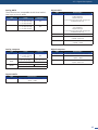
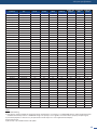
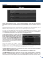
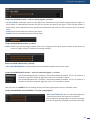
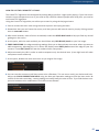
4.5.5 Output Computer formats
The outputs of a LiveCore™ unit support GTF (version 1.1), CVT (version 1.1) and DMT (version 1.0 rev 12)
standards. Other non-standard formats are supported via the Custom Format capability.
A LiveCore™ unit oers a list of pre-dened output formats. The list of output formats is always displayed
from increasing number of pixels per line and then number of lines.
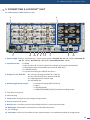
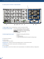
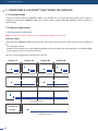
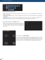
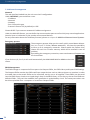
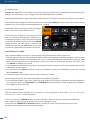
A LiveCore™ unit oers two or three input module cards. Each input module card contains 4 inputs.
Each input is composed of several plugs. A plug corresponds to a socket on the rear panel.
The following types of plugs are available on the rear panel:
- 4-Lanes DisplayPort in version 1.1a (can accept a Dual-Link DVI input via a non-supplied acve adaptor)
- HDMI
- Single DVI-I / Dual-Link DVI-D (DVI-I connector),
- 3G/HD/SD-SDI (BNC),
- Universal Analog (HD-15)
4.5.5 Output Computer formats
Format
Frequency
VGA 640x480 4/3 No Yes
WVGA 848x480 16/9 No Yes
SVGA 800x600 4/3 No Yes
720p 1280x720 16/9 Yes Yes
XGA 1024x768 4/3 Yes Yes
WXGA 1280x768 5/3 Yes Yes
SWXGA 1360x768 16/9 Yes Yes
1366x768 1366x768 16/9 Yes Yes
WXGA2 1280x800 16/9 Yes Yes
SWXGAP 1366x800 5/3 Yes Yes
XGA+ 1152x864 4/3 Yes Yes
WXGA+ 1440x900 16/10 Yes Yes
HD+ 1600x900 16/9 Yes Yes
SXGA- 1280x960 4/3 Yes Yes
WXGA+ 1440x960 3/2 Yes Yes
SXGA 1280x1024 5/4 Yes Yes
1360x1024 4/3 Yes Yes
SXGAP 1400x1050 5/3 Yes Yes
WSXGAP 1680x1050 16/9 Yes Yes
1080p 1920x1080 16/9 Yes Yes
*Dual-Link format
**Dual-Link format at 60Hz, Single-Link format at 30Hz, used with two outputs, side by side to make a 4K output
4.6
Format
Frequency
UHDTV Side
by side**
1920x2160 N/A Yes Yes
2K 2048x1080 17/9 Yes Yes
4K Side by
side**
2048x2160 N/A Yes Yes
UW-UXGA* 2560x1080 21/9 Yes Yes
QWXGA 2048x1152 16/9 Yes Yes
UXGA 1600x1200 4/3 Yes Yes
WUXGA 1920x1200 16/9 Yes Yes
WQHD* 2560x1440 16/9 Yes Yes
QXGA* 2048x1536 4/3 Yes Yes
WQXGA* 2560x1600 16/10 Yes Yes

18
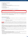
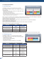
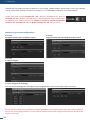
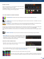
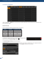
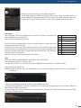
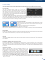
4.6 Input specicaons
A LiveCore™ unit uses an HDMI plug with a standard
mounng screw above the connector. Please see the
diagram below.
This hole is occupied by a Torx10 screw when you receive
the unit. If desired, this screw can be removed and
replaced by a compable aermarket HDMI plug locking
mechanism to ensure a secure HDMI connecon.
Please take a look at the accepted format regarding the input plug type:
WARNING: Only the video signal is processed for the HDMI®, 3G/HD/SD-SDI and DisplayPort inputs; the
embedded audio is not processed. All other HDMI® features such as: HDMI Ethernet Channel, Audio Return
Channel, 3D, Content Type, Deep Color and x.v.Color are NOT supported.
Each input can display only one acve plug at a me. It is instantly available on the device and can be
displayed simultaneously on many layers or outputs, with dierent sizes and posions. Each input can be
used independently except with the Dual-Link and Dual-Head conguraon which are using two inputs.
Plug Type Formats Signals
Universal Analog Input SDTV - EDTV - HDTV - Computer Analog SDTV - Analog EDTV - Analog HDTV - Analog Computer
DVI-A Input SDTV - EDTV - HDTV - Computer Analog SDTV - Analog EDTV - Analog HDTV - Analog Computer
DVI-D Input SDTV - EDTV - HDTV - Computer Digital SDTV - Digital EDTV - Digital HDTV - Digital Computer
DisplayPort Input SDTV - EDTV - HDTV - Computer Digital SDTV - Digital EDTV - Digital HDTV - Digital Computer
HDMI Input SDTV - EDTV - HDTV - Computer Digital SDTV - Digital EDTV - Digital HDTV - Digital Computer
HDMI 4K input* 4K DCI - UHDTV - SDTV - EDTV - HDTV Digital SDTV - Digital EDTV - Digital HDTV - Digital UHDTV
3G/HD/SD-SDI Input SDTV - HDTV Digital SDTV - Digital HDTV
M3x0,5 mm
27 mm
*only available with the 4K opon
For devices with the
4K input card:

19
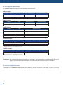
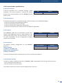
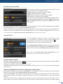
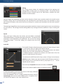
4.6 Input specicaons
Standard HD-15 3G-SDI HDMI HDMI 4K
4-Lanes
3
Dis-
playPort
Single-Link
DVI-I
Dual-Link
DVI-D
NTSC 525/480i Yes Yes Yes Yes No No No
PAL 625/576i Yes Yes Yes Yes No No No
SECAM 625/576i Yes Yes Yes Yes No No No
480p 525/480p Yes No Yes Yes Yes Yes Yes
576p 625/576p Yes No Yes Yes Yes Yes Yes
720p 1280x720 Yes Yes Yes Yes Yes Yes Yes
1035i 1920x1035 Yes Yes Yes Yes Yes Yes Yes
1080i 1920x1080 Yes Yes Yes Yes Yes Yes Yes
1080p 1920x1080 Yes Yes Yes Yes Yes Yes Yes
1080sF 1920x1080 Yes Yes Yes Yes Yes Yes Yes
1080p 1920x1080 Yes Yes Yes Yes Yes Yes Yes
DCDM 2048x1080 No Yes No No No No No
VGA 640x480 Yes No Yes Yes Yes Yes Yes
800x480 800x480 Yes No Yes Yes Yes Yes Yes
WVGA 848x480 Yes No Yes Yes Yes Yes Yes
SVGA 800x600 Yes No Yes Yes Yes Yes Yes
1280x600 1280x600 Yes No Yes Yes Yes Yes Yes
720p RGB 1280x720 Yes No Yes Yes Yes Yes Yes
XGA 1024x768 Yes No Yes Yes Yes Yes Yes
WXGA 1280x768 Yes No Yes Yes Yes Yes Yes
SWXGA 1360x768 Yes No Yes Yes Yes Yes Yes
1366x768 1366x768 Yes No Yes Yes Yes Yes Yes
800p RGB 1280x800 Yes No Yes Yes Yes Yes Yes
SWXGA+ 1366x800 Yes No Yes Yes Yes Yes Yes
1152x864 1152x864 Yes No Yes Yes Yes Yes Yes
900p RGB 1440x900 Yes No Yes Yes Yes Yes Yes
1600x900 1600x900 Yes No Yes Yes Yes Yes Yes
960p RGB 1280x960 Yes No Yes Yes Yes Yes Yes
SXGA 1280x1024 Yes No Yes Yes Yes Yes Yes
1360x1024 1360x1024 Yes No Yes Yes Yes Yes Yes
DILA4/3 1364x1024 Yes No Yes Yes Yes Yes Yes
SXGA+ 1400x1050 Yes No Yes Yes Yes Yes Yes
WSXGA+ 1680x1050 Yes No Yes Yes Yes Yes Yes
1080p RGB 1920x1080 Yes
1
No Yes Yes Yes Yes Yes
2K 2048x1080 Yes
1
No Yes Yes Yes Yes Yes
UXGA 1600x1200 Yes No Yes No Yes Yes Yes
WUXGA 1920x1200 Yes
1
No Yes Yes Yes Yes Yes
1920x1440 1920x1440 Undersampled
2
No No Yes Yes No Yes
QXGA
4
2048x1536 Undersampled
2
No No Yes Yes No Yes
2560x1080 2560x1080 No No No No Yes No Yes
2560x1440 2560x1440 No No No No No No Yes
WQXGA
4
2560x1600 No No No No Yes No Yes
2160p RGB 3840x2160 No No No Yes No No No
4K RGB
5
4096x2160 No No No Yes No No No
Notes:
1) Reduced Blanking
2) The signal is under-sampled: the image cannot be reproduced on 1:1 scaling (i.e. a 1920x1440 signal is under-sampled and then
stretched horizontally to t on a 1920x1440 image. The quality is not as good as it could be with a properly sampled signal)
3) 4-Lanes DisplayPort in version 1.1a (accept a Dual-Link DVI input via a non-supplied acve adaptor)
4) Dual-Link format
5) 4K format, only available with the 4K opon

20
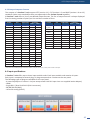
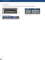
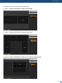
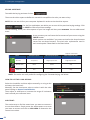
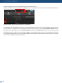
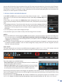
4.7.1 Standard output
A LiveCore™ unit has one monitoring output module.
This module contains one output with the following plugs:
- 3G/HD/SD-SDI (2 x BNC),
- Analog Computer/Video (HD15),
- Dual-Link DVI-I (DVI-I),
- Analog SDTV (4 × BNC: Composite, YC, YUV, RGBS).
Please see the formats available on the output:
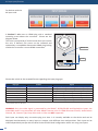
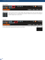
Please see the output formats of the monitoring output:
Please note that SDTV and EDTV are not available on the standard output module and require the monitoring output module.
4.7.2 Monitoring output
Output Type Format Signal
Analog Computer/Video Ouput
HDTV
Computer
Analog HDTV
Analog Computer
DVI-I Dual-Link Output
HDTV
Computer
Digital HDTV
Digital Computer
3G-SDI Output HDTV Digital HDTV
Dual Video Opcal SFP Module HDTV Digital HDTV
Output Type Format Signal
Video Y/C Output SDTV Analog SDTV
Video Y Pb Pr Output SDTV Analog SDTV
Video RGBSTTL Output SDTV Analog SDTV
Analog Computer / Video Output
SDTV
EDTV
HDTV
Computer
Analog SDTV
Analog EDTV
Analog HDTV
Analog Computer
DVI-I Dual-Link Output
SDTV
EDTV
HDTV
Computer
Digital SDTV
Digital EDTV
Digital HDTV
Digital Computer
SD-HD-3G-SDI Output
SDTV
HDTV
Digital SDTV
Digital HDTV
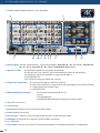
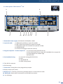
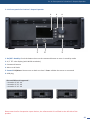
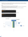
A LiveCore™ unit has two standard output modules.
The standard module contains two outputs with the
following plugs:
- 3G/HD/SD-SDI (two clone outputs via 1 BNC and 1 dual
video opcal SFP module),
- Analog Computer/Video (HD15),
- DVI: Dual-Link DVI-I for output #1 and Single-Link DVI-I on
output #2 (both with DVI-I connectors).
4.7
4.7.1 Standard output
When using the standard output module for a Dual-link DVI connecon, connect the display to output #1.
Output #2 will not be available when outpung a Dual-link DVI connecon.
When outputs #2 and #4 deliver 4K 30Hz format, output #1 and #3 are respecvely disabled
When outputs #2 delivers 4K 60Hz 4:2:0 format, all the other outputs are disabled
*
La pagina si sta caricando...
La pagina si sta caricando...
La pagina si sta caricando...
La pagina si sta caricando...
La pagina si sta caricando...
La pagina si sta caricando...
La pagina si sta caricando...
La pagina si sta caricando...
La pagina si sta caricando...
La pagina si sta caricando...
La pagina si sta caricando...
La pagina si sta caricando...
La pagina si sta caricando...
La pagina si sta caricando...
La pagina si sta caricando...
La pagina si sta caricando...
La pagina si sta caricando...
La pagina si sta caricando...
La pagina si sta caricando...
La pagina si sta caricando...
La pagina si sta caricando...
La pagina si sta caricando...
La pagina si sta caricando...
La pagina si sta caricando...
La pagina si sta caricando...
La pagina si sta caricando...
La pagina si sta caricando...
La pagina si sta caricando...
La pagina si sta caricando...
La pagina si sta caricando...
La pagina si sta caricando...
La pagina si sta caricando...
La pagina si sta caricando...
La pagina si sta caricando...
La pagina si sta caricando...
La pagina si sta caricando...
La pagina si sta caricando...
La pagina si sta caricando...
La pagina si sta caricando...
La pagina si sta caricando...
La pagina si sta caricando...
La pagina si sta caricando...
La pagina si sta caricando...
La pagina si sta caricando...
La pagina si sta caricando...
La pagina si sta caricando...
La pagina si sta caricando...
La pagina si sta caricando...
La pagina si sta caricando...
La pagina si sta caricando...
La pagina si sta caricando...
La pagina si sta caricando...
La pagina si sta caricando...
La pagina si sta caricando...
La pagina si sta caricando...
La pagina si sta caricando...
La pagina si sta caricando...
La pagina si sta caricando...
La pagina si sta caricando...
La pagina si sta caricando...
La pagina si sta caricando...
La pagina si sta caricando...
La pagina si sta caricando...
La pagina si sta caricando...
La pagina si sta caricando...
La pagina si sta caricando...
La pagina si sta caricando...
La pagina si sta caricando...
La pagina si sta caricando...
La pagina si sta caricando...
La pagina si sta caricando...
La pagina si sta caricando...
La pagina si sta caricando...
La pagina si sta caricando...
La pagina si sta caricando...
La pagina si sta caricando...
La pagina si sta caricando...
La pagina si sta caricando...
La pagina si sta caricando...
La pagina si sta caricando...
La pagina si sta caricando...
La pagina si sta caricando...
La pagina si sta caricando...
La pagina si sta caricando...
La pagina si sta caricando...
La pagina si sta caricando...
La pagina si sta caricando...
La pagina si sta caricando...
La pagina si sta caricando...
La pagina si sta caricando...
La pagina si sta caricando...
La pagina si sta caricando...
La pagina si sta caricando...
La pagina si sta caricando...
La pagina si sta caricando...
La pagina si sta caricando...
La pagina si sta caricando...
La pagina si sta caricando...
La pagina si sta caricando...
La pagina si sta caricando...
La pagina si sta caricando...
La pagina si sta caricando...
La pagina si sta caricando...
La pagina si sta caricando...
La pagina si sta caricando...
La pagina si sta caricando...
La pagina si sta caricando...
-
 1
1
-
 2
2
-
 3
3
-
 4
4
-
 5
5
-
 6
6
-
 7
7
-
 8
8
-
 9
9
-
 10
10
-
 11
11
-
 12
12
-
 13
13
-
 14
14
-
 15
15
-
 16
16
-
 17
17
-
 18
18
-
 19
19
-
 20
20
-
 21
21
-
 22
22
-
 23
23
-
 24
24
-
 25
25
-
 26
26
-
 27
27
-
 28
28
-
 29
29
-
 30
30
-
 31
31
-
 32
32
-
 33
33
-
 34
34
-
 35
35
-
 36
36
-
 37
37
-
 38
38
-
 39
39
-
 40
40
-
 41
41
-
 42
42
-
 43
43
-
 44
44
-
 45
45
-
 46
46
-
 47
47
-
 48
48
-
 49
49
-
 50
50
-
 51
51
-
 52
52
-
 53
53
-
 54
54
-
 55
55
-
 56
56
-
 57
57
-
 58
58
-
 59
59
-
 60
60
-
 61
61
-
 62
62
-
 63
63
-
 64
64
-
 65
65
-
 66
66
-
 67
67
-
 68
68
-
 69
69
-
 70
70
-
 71
71
-
 72
72
-
 73
73
-
 74
74
-
 75
75
-
 76
76
-
 77
77
-
 78
78
-
 79
79
-
 80
80
-
 81
81
-
 82
82
-
 83
83
-
 84
84
-
 85
85
-
 86
86
-
 87
87
-
 88
88
-
 89
89
-
 90
90
-
 91
91
-
 92
92
-
 93
93
-
 94
94
-
 95
95
-
 96
96
-
 97
97
-
 98
98
-
 99
99
-
 100
100
-
 101
101
-
 102
102
-
 103
103
-
 104
104
-
 105
105
-
 106
106
-
 107
107
-
 108
108
-
 109
109
-
 110
110
-
 111
111
-
 112
112
-
 113
113
-
 114
114
-
 115
115
-
 116
116
-
 117
117
-
 118
118
-
 119
119
-
 120
120
-
 121
121
-
 122
122
-
 123
123
-
 124
124
-
 125
125
-
 126
126
-
 127
127


in altre lingue
- English: Analog way ASC3204-4K-PL User manual
Documenti correlati
-
Analog way Pulse Manuale utente
-
-
Analog way Pulse 4K Manuale utente
-
-
-
-
-
-
-
Altri documenti
-
NDS Radiance Manuale del proprietario
-
-
AJA R20DA Manuale utente
-
-
AJA R5CE Manuale utente
-
Hama 39042553 Manuale del proprietario
-
-
 AWG XBOX 360 & WII Manuale del proprietario
-
PNI MP10 Manuale utente
-
Crowcon T4 Manuale utente
