Viessmann 5271 Manuale del proprietario
- Categoria
- Accessori per la preparazione del caffè
- Tipo
- Manuale del proprietario

89050
Stand 03/sw
03/2022
Ho/Kf
Made in Europe
Viessmann Modelltechnik GmbH
Bahnhofstraße 2a
D - 35116 Hatzfeld-Reddighausen
+49 6452 9340-0
www.viessmann-modell.de
Bedienungsanleitung
Operation Manual
Mini-LED mit Mikro-Blinkelektronik
Mini-LED with micro-blinking
electronics
5270
gelb, 2 Stück / yellow, 2 pieces
5271
blau, 2 Stück / blue, 2 pieces
5272
rot, 2 Stück / red, 2 pieces
5273
Feuer rot-gelb, 3 Stück / re
red-yellow, 3 pieces
1. Wichtige Hinweise
Bitte lesen Sie vor der ersten Anwendung des Produk-
tes bzw. dessen Einbau diese Bedienungsanleitung
aufmerksam durch. Bewahren Sie diese auf, sie ist
Teil des Produktes.
1.1 Sicherheitshinweise
Vorsicht:
Verletzungsgefahr!
Aufgrund der vorgesehenen Verwendung kann das
Produkt Spitzen, Kanten und abbruchgefährdete
Teile aufweisen. Für die Montage sind Werkzeu-
ge nötig.
Stromschlaggefahr!
Die Anschlussdrähte niemals in eine Steckdose
einführen! Verwendetes Versorgungsgerät (Trans-
formator, Netzteil) regelmäßig auf Schäden über-
prüfen. Bei Schäden am Versorgungsgerät dieses
keinesfalls benutzen!
Alle Anschluss- und Montagearbeiten nur bei abge-
schalteter Betriebsspannung durchführen!
Ausschließlich nach VDE/EN gefertigte Modell-
bahntransformatoren verwenden!
Stromquellen unbedingt so absichern, dass es bei
einem Kurzschluss nicht zum Kabelbrand kom-
men kann.
1.2 Das Produkt richtig verwenden
Dieses Produkt ist bestimmt:
- Zum Einbau in Modelleisenbahnanlagen und
Dioramen.
- Zum Anschluss an einen Modellbahntransformator
(z. B. Art. 5200) bzw. an eine Modellbahnsteuerung
mit zugelassener Betriebsspannung.
- Zum Betrieb in trockenen Räumen.
Jeder darüber hinausgehende Gebrauch gilt als nicht
bestimmungsgemäß. Für daraus resultierende Schä-
den haftet der Hersteller nicht.
1.3 Packungsinhalt überprüfen
Kontrollieren Sie den Lieferumfang auf Vollständigkeit:
- Mini-LEDs mit Mikro-Blinkelektronik
- Anleitung
2. Einleitung
Art. 5270, 5271
Besonders kompakte Blinkelektronik, die sich wegen
der kleinen Abmessungen direkt in Fahrzeuge ein-
bauen lässt.
Art. 5272, 5273
Besonders kompakte Blinkelektronik, die sich wegen
der kleinen Abmessungen besonders gut in Modellge-
bäude integrieren lässt und für ein realistisches Brand-
flackern sorgt.
Die LEDs blinken unabhängig voneinander. Der Be-
trieb ist auch mit einer LED allein möglich. Zur einfa-
chen Verdrahtung sind bereits Drähte an den LEDs
angelötet
DE
14
2. Introduction
Compact blinking electronics which can be mounted
directly into the vehicles. The LEDs blink separately.
Operation with only one LED is possible. Easy wiring
by already soldered wires on the LEDs.
3. Mounting
Check the function before installation. Connect the
LEDs with blinking electronics as shown in fig. 1.
3.1 Mounting instruction item 5273
- One red LED is on the roof, facing downwards.
- The yellow LED is on the side, facing inwards.
- The last LED is placed on the floor, facing upwards.
Hint: Particularly suitable as a replacement for Vollmer
item 46560 Flickering light red, 16 V.
4. Connection
4.1 Connection in AC operation
Connect the blinking electronics acc. to fig. 1. The unit
will start to blink slowly. If you want to change the blink-
ing rhythm into a faster blinking, please follow the in-
structions given under point 4.3 Changing the blink-
ing rhythm.
4.2 Connection in DC operation
Connect the blinking electronics acc. to fig. 4. The unit
will start to blink slowly. If you want to change the blink-
ing rhythm into a faster blinking, please follow the in-
structions given under point 4.3 Changing the blink-
ing rhythm.
4.3 Changing the blinking rhythm
In order to change the blinking rhythm, proceed as
follows:
Items 5270, 5271
- Separate the electronics from the power supply.
- Connect the black wire with the yellow one (fig. 2).
- Reconnect the electronics with the pwer supply
(fig. 3).
In order to change back into the slower blinking
rhythm, separate the electronics from the power sup-
ply, separate the black wire from the yellow one and
reconnect the electronics with the power supply.
Items 5272, 5273
- There is no need for you to separate the power
supply from the electronics during this process.
Black and yellow cable may be connected or sepa-
rated during operation. You may also use a switch
(item 5550) for the separation resp. connection of
the black and yellow wire.
5. Technical data
Operating voltage: 14 – 24 V DC=
10 – 16 V AC~
Dimensions
Electronics: L 2.5 x B 0.4 x H 0.3 cm
LEDs: L 0.16 x B 0.08 cm
Änderungen vorbehalten. Keine Haftung für Druckfehler und Irr-
tümer.
Die aktuelle Version der Anleitung finden Sie auf der Viessmann
Homepage unter der Artikelnummer.
Subject to change without prior notice. No liability for mistakes
and printing errors.
You will nd the latest version of the manual on the Viessmann
website using the item number.
Entsorgen Sie dieses Produkt nicht über den (un-
sortierten) Hausmüll, sondern führen Sie es der
Wiederverwertung zu.
Do not dispose of this product through (unsorted)
domestic waste, supply it to recycling instead.
Modellbauartikel, kein Spielzeug! Nicht geeignet
für Kinder unter 14 Jahren! Anleitung aufbewahren!
Model building item, not a toy! Not suitable for
children under the age of 14 years! Keep these
instructions!
Ce n’est pas un jouet! Ne convient pas aux en-
fants de moins de 14 ans! Conservez cette notice
d’instructions!
Não é um brinquedo! Não aconselhável para
menores de 14 anos! Conservar o manual de in-
struções!
Modelbouwartikel, geen speelgoed! Niet geschikt
voor kinderen onder 14 jaar! Gebruiksaanwijzing
bewaren!
Articolo di modellismo, non è un giocattolo! Non
adatto a bambini al di sotto dei 14 anni! Conservare
istruzioni per l’uso!
Artículo para modelismo ¡No es un juguete! No
recomendado para menores de 14 años! Conserva
las instrucciones de servicio!
DE
EN
FR
NL
IT
ES
PT

32
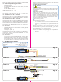
3. Einbau
Prüfen Sie vor dem Einbau die Funktion. Schließen Sie
die LEDs mit Blinkelektronik gemäß Abb. 1 an.
3.1 Einbauempfehlung Art. 5273
- Eine rote LED befindet sich unter dem Dach, nach
unten gerichtet.
- Die gelbe LED befindet sich auf der Seite, die nach
innen zeigt.
- Die letzte LED wird mit der Ausrichtung nach oben
auf den Boden gelegt.
Tipp: Eignet sich besonders als Ersatz des Vollmer Art.
46560 Flackerlicht rot, 16 V.
4. Anschluss
Alle Module sind sowohl für den AC- als auch DC-
Betrieb geeignet.
4.1 Anschluss im AC~ Betrieb
Schließen Sie die Blinkelektronik gemäß Abb. 1 an. Da-
durch erreichen Sie ein langsames Blinken. Zum Ändern
des Blinkrhythmus in ein schnelleres Blinken, befolgen
Sie die Anweisungen unter 4.3 Blinkrhythmus ändern.
4.2 Anschluss im DC= Betrieb
Schließen Sie die Blinkelektronik gemäß Abb. 4 an. Da-
durch erreichen Sie ein langsames Blinken. Zum Ändern
des Blinkrhythmus in ein schnelleres Blinken, befolgen
Sie die Anweisungen in Kapitel 4.3 Blinkrhythmus ändern.
4.3 Blinkrhythmus ändern
Zum Ändern des Blinkrhythmus gehen Sie folgender-
maßen vor:
Art. 5270, 5271
- Trennen Sie die Elektronik von der Stromversorgung.
- Verbinden Sie das schwarze Kabel mit dem gelben
Kabel (Abb. 2).
- Verbinden Sie die Elektronik wieder mit der Strom-
versorgung (Abb. 3).
Um wieder zu dem langsameren Blinkrhythmus zu
wechseln, trennen Sie die Elektronik von der Strom
-
versorgung, trennen das schwarze Kabel von dem
gelben Kabel und verbinden die Elektronik wieder mit
der Stromversorgung.
Art. 5272, 5273
- Sie müssen die Stromversorgung während des
Vorgangs nicht von der Elektronik trennen. Die
schwarze Leitung kann also während des Be-
triebs mit der gelben Leitung verbunden oder ge-
trennt werden. Die Trennung oder Verbindung der
schwarzen Leitung an die gelbe Leitung kann auch
mit einem Schalter (Art. 5550) realisiert werden.
5. Technische Daten
Betriebsspannung: 14 – 24 V DC=
10 – 16 V AC~
Maße
Elektronik: L 2,5 x B 0,4 x H 0,3 cm
LEDs: L 0,16 x B 0,08 cm
Sekundär
0-10-16 V~
16 V
Primär
230 V~
Gefertigt nach
VDE 0570
EN 61558
Lichttransformator
5200
Nur für trockene Räume
Primär 230 V 50 - 60 Hz
Sekundär max. 3,25 A52 VA
ta 25°CIP 40
10 V
0 V
z. B. / e. g. 5200
gelb / yellow
schwarz / black
braun
brown
Abb. 1 Fig. 1
gelb
yellow
braun
brown
schwarz
black
z. B. / e. g. 5200
Sekundär
0-10-16 V~
16 V
Primär
230 V~
Gefertigt nach
VDE 0570
EN 61558
Lichttransformator
5200
Nur für trockene Räume
Primär 230 V 50 - 60 Hz
Sekundär max. 3,25 A52 VA
ta 25°CIP 40
10 V
0 V
Sekundär
0-10-16 V~
16 V
Primär
230 V~
Gefertigt nach
VDE 0570
EN 61558
Lichttransformator
5200
Nur für trockene Räume
Primär 230 V 50 - 60 Hz
Sekundär max. 3,25 A52 VA
ta 25°CIP 40
10 V
0 V
gelb
yellow
braun
brown
schwarz
black
z. B. / e. g. 5200
Abb. 2 Fig. 2
Abb. 3 Fig. 3
Abb. 4 Fig. 4
Sekundär
0-10-16 V~
16 V
Primär
230 V~
Gefertigt nach
VDE 0570
EN 61558
Lichttransformator
5200
Nur für trockene Räume
Primär 230 V 50 - 60 Hz
Sekundär max. 3,25 A52 VA
ta 25°CIP 40
10 V
0 V
gelb / yellow
braun / brown
gelb
yellow
braun
brown
schwarz / black
z. B. / e. g. 5200
z. B. / e. g.
5215
1. Important information
Please read this manual completely and attentively
before using the product for the first time. Keep this
manual. It is part of the product.
1.1 Safety instructions
Caution:
Risk of injury!
Due to the detailed reproduction of the original and
the intended use, this product can have peaks, edg-
es and breakable parts. Tools are required for in-
stallation.
Electrical hazard!
Never put the connecting wires into a power sock-
et! Regularly examine the transformer for damage.
In case of any damage, do not use the transformer.
Make sure that the power supply is switched off
when you mount the device and connect the cables!
Only use VDE/EN tested special model train trans-
formers for the power supply!
The power sources must be protected to avoid the
risk of burning cables.
1.2 Using the product for its correct purpose
This product is intended:
- For installation in model train layouts and dioramas.
- For connection to an authorized model train trans-
former (e. g. item 5200) or a digital command sta-
tion.
- For operation in dry rooms only.
Using the product for any other purpose is not ap-
proved and is considered inappropriate. The manu-
facturer is not responsible for any damage resulting
from the improper use of this product.
1.3 Checking the package contents
Check the contents of the package for completeness:
- Mini-LED with micro-blinking electronics
- Manual
-
 1
1
-
 2
2


Viessmann 5271 Manuale del proprietario
- Categoria
- Accessori per la preparazione del caffè
- Tipo
- Manuale del proprietario
in altre lingue
- English: Viessmann 5271 Owner's manual
- Deutsch: Viessmann 5271 Bedienungsanleitung
Documenti correlati
-
Viessmann 1539 Manuale del proprietario
-
-
-
-
-
-
-
-
-