Tecnosystemi STEALTH 3X built-in wired backlit programmable thermostat Manuale del proprietario
- Tipo
- Manuale del proprietario

Tecnosystemi S.p.A. Società Benet
Via dell'Industria 2/4 - z.i. San Giacomo di Veglia 31029 Vittorio Veneto Treviso
Tel. 0438 - 500044 / Fax. 0438 - 501516 - NUMERO VERDE 800 904474
[email protected] - www.tecnosystemi.com
1. CRONOTERMOSTATO AD INCASSO CABLATO
TOUCH “STEALTH 3X”
1.1 USO BASE DEL TERMOSTATO PER L’UTENTE
Il cronotermostato Stealth 3X, permette la regolazione della temperatura di Setpoint diversa
da zona a zona, la regolazione del usso dell’aria e l’impostazione in funzione Termostato o
Cronotermostato, permettendo così di soddisfare le esigenze di impostazione in autonomia
in qualsiasi momento. Nel manuale sono illustrate le impostazioni, l’uso e la congurazione
del Cronotermostato. ATTENZIONE! IL MONTAGGIO DEL CRONOTERMOSTATO DEVE
ESSERE ESEGUITO SOLO A COMPLETAMENTO DELLE OPERE MURARIE.
Fig. 1
Fig. 2 Fig. 3
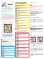
Le icone presenti sul cronotermostato sono suddivise in tre fasce ( Fig.1 ):
ICONE TOUCH DELLA TASTIERA: si riferiscono alla regolazione generale
del cronotermostato.
ICONE VISIONE DELLE IMPOSTAZIONIICONE VISIONE DELLE IMPOSTAZIONI: si riferiscono alle impostazioni del-
le funzioni del cronotermostato.
ICONE VISIONE DELLE INDICAZIONI: si riferiscono alle indicazioni.
ICONE TOUCH DELLA TASTIERA
Tasto INVIO . Conferma del dato, per entrare nel sotto menù e / o
per lo Sblocco / Blocco del cronotermostato.
Tasto MENO. Modica un valore in negativo.
Tasto ON / OFF. Per accensione / spegnimento del cronotermo-
stato e uscita dal menù.
Tasto PIÙ. Modica un valore in positivo.
Tasto SET. Per accedere al Menù principale e per scegliere le
impostazioni.
ICONE VISIONE DELLE IMPOSTAZIONIICONE VISIONE DELLE IMPOSTAZIONI
ICONE VISIONE DELLE INDICAZIONI
1. BLOCCO / SBLOCCO DEL CRONOTERMOSTATO
La presenza del simbolo indica che la tastiera è bloccata. Il cronotermostato
prevede il blocco dei tasti per evitare pressioni o modiche accidentali delle impostazioni
(esempio durante la pulizia del cronotermostato o utilizzo del cronotermostato da parte di
bambini,ecc..). Questa funzione si attiva automaticamente trascorsi 60 secondi dall’ultima
pressione di un tasto o manualmente.
Procedura:
1.1 Premere il tasto per 3 secondi, sia per attivare o disattivare il Blocco tastiera
. (Se il cronotermostato risulta in OFF, tutti i termostati compreso il cronotermostato
MASTER non andranno mai in blocco)
2. ACCENSIONE / SPEGNIMENTO DEL SISTEMA. (SOLO DAL
CRONOTERMOSTATO MASTER)
Per spegnere l’intero sistema Proair agire sul cronotermostato impostato come
MASTER.
Procedura:
2.1 Premere il tasto per 3 secondi, vericando l’indicazione ZONA “1”
OFF e il lampeggio della sigla “MASTER OFF”. (Fig.2)
2.2 Prima che “MASTER OFF” smetta di lampeggiare (max 8 secondi),
premere nuovamente il tasto . Quando le impostazioni “MASTER OFF”
e “ZONA 1 OFF” non lampeggeranno più, si chiuderanno tutte le serrande
o bocchette motorizzate e si spegnerà l’unità canalizzata. (aggiornamento dei
cronotermostati nel tempo max. di 5min)
2.3 Per riaccendere l’intero sistema è necessario premere per 3 secondi
il tasto del cronotermostato MASTER.Sul cronotermostato apparirà la
sigla “MASTER ON” e su tutti gli altri cronotermostati non sarà visibile la
scritta “OFF”. (Fig.3).
A
A
25
ATTENZIONE:
Il sistema di comunicazione tra cronotermostati e centralina avviene tramite cavo
4 x 0,22: qualsiasi impostazione eseguita sui cronotermostati viene inviata e
gestita dalla centralina in tempo reale.
In questa fase sono evidenziate le congurazioni base del termostato di zona e del
sistema;
1. BLOCCO / SBLOCCO DEL CRONOTERMOSTATO
2. ACCENSIONE / SPEGNIMENTO DEL SISTEMA (SOLO DA CRONOTERMOSTATO MASTER)
3. ACCENSIONE / SPEGNIMENTO DEL CRONOTERMOSTATO DI ZONA
4. IMPOSTAZIONE DELLA TEMPERATURA DESIDERATA
5. IMPOSTAZIONE ESTATE / INVERNO
6. SEGNALAZIONE DEGLI ERRORI
25
MASTER
OFF
OFF
OFF 25
MASTER
ON
1.2 CONFIGURAZIONI DI BASE
ON
TERMOSTATO IN FUNZIONE MANUALE. Imposta solo la
temperatura in modo manuale.
CRONOTERMOSTATO (TIMER). Programma le fasce orarie
e la temperatura.
MOVIMENTO SERRANDA. Imposta la posizione di apertura
della serranda o bocchetta motorizzata.
RAFFRESCAMENTO (ESTATE). Imposta il sistema in
raffrescamento.
RISCALDAMENTO (INVERNO). Imposta il sistema in riscaldamento
(pompa di calore).
PERCENTUALE DI UMIDITÀ. Indica la percentuale di umidità
rilevata nell’ambiente.
OROLOGIO. Indica ora e minuti (AM - PM / 24h).
GIORNO. Indica il giorno settimanale.
TEMPERATURA. Indica la temperatura desiderata in gradi °C
(centigradi) o °F (fahrenheit).
MASTER. Indica che è il cronotermostato principale di gestione
dell’impianto.
A
C
A
SETTING. Si accende durante le fasi di impostazione
del cronotermostato.
BLOCCO TASTIERA. Indica che la tastiera è bloccata.
SERRANDA O BOCCHETTA CHIUSA. Indica la chiusura
della serranda / bocchetta
LIVELLO DI CONFORT. Indica la funzione di risparmio energetico.
POSIZIONE APERTURA DELLE SERRANDE O BOCCHETTE.
Indica l’ apertura delle serrande / bocchette motorizzate.
VALVOLA DI ZONA. Indica la funzione di riscaldamento
(momentaneamente non attivata)
PERCENTUALE DI UMIDITÀ. Indica la percentuale di umidità
rilevata nell’ambiente.
A
REV 01 / 2023
25/07/2023
CLI00108

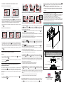
VITI IN DOTAZIONE
3. ACCENSIONE - SPEGNIMENTO DEL CRONOTERMOSTATO DI ZONA
Procedura dal cronotermostato MASTER:
3.1 Sul cronotermostato MASTER, premere il tasto per 3 secondi vericando la
sigla ZONA OFF e il lampeggio della sigla MASTER OFF (Fig.4). Trascorsi 8 secondi
apparirà la scritta MASTER ON (Fig.5), in questo modo solo il cronotermostato MASTER
risulterà spento, mentre il resto dei cronotermostati (e del sistema) risulterà acceso.
3.2 Per riaccendere il cronotermostato è necessario premere nuovamente per 3 secondi
il tasto .
Procedura dei cronotermostati di zona:
3.3 Supponiamo di avere 4 cronotermostati associati a 4 zone e vogliamo spegnere solo il
cronotermostato di Zona 2: premere il tasto per 3 secondi verificando l’indicazione
ZONA 2 OFF (Fig.6). In questo modo, solo il cronotermostato di zona risulterà
spento, mentre il resto dei cronotermostati (e del sistema) risulterà acceso. (Fig.7/8)
3.4 Per riaccendere il cronotermostato è necessario premere nuovamente per 3 secondi
il tasto .
4. IMPOSTAZIONE DELLA TEMPERATURA DESIDERATA
Procedura:
4.1 Per impostare la temperatura, se il cronotermostato è bloccato è necessario
premere per 3 secondi il tasto
4.2 Premere il tasto o per modicare il valore di temperatura, per confermare
premere il tasto .
5. IMPOSTAZIONE ESTATE – INVERNO DEL SISTEMA PROAIR (SOLO DAL
CRONOTERMOSTATO MASTER)
Per impostare la modalità estate / inverno del sistema Proair, è necessario accedere
all’interno dei parametri del cronotermostato MASTER. Per accedere è necessario
che il cronotermostato risulti “sbloccato” e in ON (acceso). La stessa impostazione dovrà
essere eseguita anche sul comando della macchina canalizzata rispettando le istruzioni
della stessa.
Procedura:
5.1 Premere il tasto per 3 secondi vericando l’accensione del simbolo e il
lampeggio del simbolo .(Fig.9)
5.2 Raffrescamento ( ). Con crono master sbloccato, entrare in modalità setting e mediante
il tasto e scegliere il simbolo e confermare con il tasto . Se il sistema prevede il
protocollo di comunicazione IR ed è attivo il Telecomando IR, vericare il lampeggio del valore
23 al centro del display LCD (Fig. 10).
Con i tasti e , denire il SetPoint della canalizzata e confermare con il tasto . Per
denire il SetPoint, considerare quanto indicato di seguito:
a. Si consiglia di impostare la temperatura di SetPoint della canalizzata, uno o due gradi più in
basso del valore di Setpoint impostati sui comandi di zona;
b. Il valore di Setpoint impostabile per la canalizzata varia da min 18°C a max 30°C (fare sempre
riferimento al manuale d’uso del telecomando del costruttore).
5.3 Riscaldamento ( ). Con crono master sbloccato, entrare in modalità setting e mediante il
tasto scegliere il simbolo e confermare con il tasto . Se il sistema prevede il protocollo
di comunicazione IR ed è attivo il Telecomando IR, vericare il lampeggio del valore 23 al centro
del display LCD (Fig. 11).
Con i tasti e , denire il SetPoint della canalizzata e confermare con il tasto . Per
denire il SetPoint, considerare quanto indicato di seguito:
a. Si consiglia di impostare la temperatura di SetPoint della canalizzata, uno o due gradi più in
alto del valore di Setpoint impostati sui comandi di zona;
b. Il valore di Setpoint impostabile per la canalizzata varia da min 18°C a max 30°C (fare sempre
riferimento al manuale d’uso del telecomando del costruttore).
5.4 Deumidificazione ( + “dE“). Con crono master sbloccato, entrare in modalità setting e
mediante il tasto scegliere il simbolo (lampeggiante) + “dE” e confermare con il tasto .
Questa impostazione prevede l’apertura al 100% di tutte le serrande presenti nel sistema per
garantire alla macchina canalizzata di deumidicare in tutte le zone presenti nel sistema (Fig.
12). Nel caso in cui non si intenda utilizzare questa nzione in una o più zone del sistema, sarà
possibile operare come di seguito indicato:
a. Chiudere la serranda spegnendo il termostato di zona (zona OFF)
b. Parzializzare l’apertura della serranda alla posizione desiderata.
5.5 Ventilazione ( ). Con crono master sbloccato, entrare in modalità setting, e mediante il
tasto scegliere il simbolo e confermare con il tasto . Questa impostazione prevede
l’apertura al 100% di tutte le serrande presenti nel sistema per garantire alla macchina canalizzata
di deumidicare in tutte le zone presenti nel sistema (Fig. 13). Nel caso in cui non si intenda
utilizzare questa nzione in una o più zone del sistema, sarà possibile operare come di seguito
indicato:
a. Chiudere la serranda spegnendo il termostato di zona (zona OFF)
b. Parzializzare l’apertura della serranda alla posizione desiderata.
5.6 Velocità del ventilatore UI (solo se il sistema prevede il protocollo di comunicazione IR ed
è attivo il Telecomando IR). Con crono master sbloccato, entrare in modalità setting, e median-
te il tasto visualizzare la sigla F al centro del LCD e confermare con il tasto per visua-
1.3 FISSAGGIO DEL CRONOTERMOSTATO STEALTH 3X
25
MASTER
OFF 25
MASTER
ON
OFF
OFF
OFF ON
25
2 OFF
ZONA 2 OFF
21
3 OFF
ZONA 3 ON
23
4 OFF
ZONA 4 ON
MURATURA
VISTA DALL’ALTO
CRONOTERMOSTATO
STEALTH 3X
CONNETTORE
ADATTATORE
PER SCATOLA E503
VITE VITE
Fig. 4
Fig. 6 Fig. 8Fig. 7
Fig. 5
6. SEGNALAZIONE DI ERRORI (appaiono nel display)
E0: Accompagnato al lampeggio del simbolo indica la mancanza di
comunicazione RF (Radio frequenza) con la Centralina di comando del sistema.
E1: Non è assegnato il MASTER su alcun cronotermostato di Zona.
E2: Attuatore (motore) serranda o bocchetta non congurate correttamente.
E3: Mancata comunicazione tra centralina e motore, ricontrollare i cablaggi e i cavi
di alimentazione o vericare che il motore non sia in avaria (contattare l’installatore
o eventualmente l’assistenza tecnica). (Fig.15)
Fig.9
Fig.12
Fig.10
Fig.13
Fig.11
Fig.14
F1
F3
F2
FA
de
-F
lizzare FA (Fan Automatico, impostazione di default del sistema). Utilizzare i tasti
e per impostare le velocità F1-F2-F3-FA per denire la velocità del ventilatore
dell’Unità Canalizzata F1-F2-F3. Velocità ssa del ventilatore (Fig. 14).
FA. Velocità gestita dal sistema Proair che aumenta o diminuisce in modo
proporzionale all’apertura/chiusura delle serrande. La regolazione del ventilatore
non modica le curve di prevalenza impostate di fabbrica dal costruttore dell’unità
canalizzata
DOWNLOAD USER MANUAL
in english language

MASTER
Tecnosystemi S.p.A. Benefit Corporation
Via dell'Industria 2/4 - z.i. San Giacomo di Veglia 31029 Vittorio Veneto Treviso
Tel. 0438 - 500044 / Fax. 0438 - 501516 - FREE-PHONE NUMBER 800 904474
[email protected] - www.tecnosystemi.com
1. “STEALTH 3X” TOUCH WIRED BUILT-IN CHRONO-
THERMOSTAT
1.1 BASIC USE OF THE THERMOSTAT FOR THE USER
The Stealth 3X chronothermostat allows regulation of the different Setpoint temperatures from
zone to zone, the regulation of the air ow and the setting in Thermostat or Chronothermostat
function, thus being able to satisfy the setting requirements autonomously at any time. The
manual illustrates the settings, use and conguration of the chronothermostat. ATTENTION!
THE ASSEMBLY OF THE CHRONOTHERMOSTAT MUST BE PERFORMED ONLY ON
COMPLETION OF THE MASONRY WORKS.
Fig. 1
Fig. 2 Fig. 3
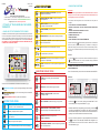
The icons on the chronothermostat are divided into three bands ( Fig.1 ):
KEYPAD TOUCH ICONS: they refer to the general setting of the chronother-
mostat.
SETTING DISPLAY ICONSSETTING DISPLAY ICONS: they refer to the settings of the chronothermo-
stat functions.
INDICATION DISPLAY ICONS: they refer to the indications.
KEYPAD TOUCH ICONS
ENTER key. Conrmation of the data, to enter the sub-menu and
/ or to Unlock / Lock the chronothermostat.
MINUS key. Changes a value to negative.
ON / OFF key. For turning of the chronothermostat on / off and for
exiting of the menu.
PlUS key. Changes a value to positive.
SET key. To access the main menu and to choose the settings.
ICONS VIEW SETTINGSICONS VIEW SETTINGS
INDICATION DISPLAY ICONS
1. LOCK / RELEASE OF THE CHRONOTHERMOSTAT
The presence of the symbol indicates that the keypad is locked. The chronothermostat
features a key lock to prevent accidental pressing or modication of the settings (for
example when cleaning the chronothermostat or use of the chronothermostat by children,
etc.). This function is activated automatically 60 seconds after the last pressing of a key
or manually.
Procedure:
1.1 Press the keyfor 3 seconds, either to activate or deactivate the Keypad lock
. (If the chronothermostat is OFF, all the thermostats including the MASTER
chronothermostat will never go into lockout)
2. TURNING THE SYSTEM ON / OFF. (ONLY FROM THE MASTER
CHRONOTHERMOSTAT)
To turn off the entire Proair system, use the chronothermostat set as MASTER.
Procedure:
2.1 Press the key for 3 seconds, checking the indication ZONE "1" OFF
and the ashing of the acronym "MASTER OFF”. (Fig.2)
2.2 Before “MASTER OFF” stops ashing (max 8 seconds), press the key
again. When the “MASTER OFF” and “ZONE 1 OFF” settings no longer ash,
all the motorised dampers or vents will close and the ducted unit will switch off.
(updating of the chronothermostats in a maximum time of 5min)
2.3 To turn the entire system back on, press the MASTER chronothermostat
key for 3 seconds. The abbreviation "MASTER ON" will appear on the
chronothermostat and the word "OFF" will not be visible on all the other
chronothermostats. (Fig.3).
A
A
25
ATTENTION:
The communication system between the chronothermostats and the control unit
takes place via a 4 x 0.22 cable: any setting made on the chronothermostats is sent
and managed by the control unit in real time.
In this phase the basic congurations of the zone thermostat and of the system are
highlighted;
1. LOCK / RELEASE OF THE CHRONOTHERMOSTAT
2. TURNING THE SYSTEM ON / OFF (ONLY FROM THE MASTER CHRONOTHER-
MOSTAT)
3. TURNING THE ZONE CHRONOTHERMOSTAT ON / OFF
4. DESIRED TEMPERATURE SETTING
5. SUMMER / WINTER SETTING
6. REPORTING ERRORS
25
OFF
OFF 25
MASTER
ON
1.2 BASIC CONFIGURATIONS
ON
THERMOSTAT IN MANUAL OPERATION. Only sets the
temperature in manual mode.
CHRONOTHERMOSTAT (TIMER). Programs the time slots
and the temperature.
DAMPER MOVEMENT. Sets the opening position
of the damper or motorised nozzle.
COOLING (SUMMER). Sets the system to
cooling.
HEATING (WINTER). Sets the system to heating (heat pump).
PERCENTAGE OF HUMIDITY. Indicates the percentage of humidity
detected in the environment.
CLOCK. Indicates hours and minutes (AM - PM / 24h).
DAY. Indicates the day of the week.
TEMPERATURE. Indicates the desired temperature in degrees °C
(centigrade) or °F (Fahrenheit).
MASTER. Indicates that it is the main system management chrono-
thermostat.
A
C
A
SETTINGS. It turns on during the chronothermostat
setting phases.
KEYPAD LOCK. Indicates that the keypad is locked.
DAMPER OR NOZZLE CLOSED. Indicates closure
of the damper / nozzle
LEVEL OF COMFORT. Indicates the energy saving function.
OPENING POSITION OF THE DAMPERS OR VENTS.
Indicates the opening of the motorised dampers / vents.
ZONE VALVE. Indicates the heating function
(currently not activated)
PERCENTAGE OF HUMIDITY. Indicates the percentage of humidity
detected in the environment.
A
REV 01 / 2023
25/07/2023
CLI00108

3. SWITCHING ON - SWITCHING OFF THE ZONE CHRONOTHERMOSTAT
Procedure from the MASTER chronothermostat:
3.1 On the MASTER chronothermostat, press the key for 3 seconds checking the text
ZONE OFF and the ashing of the text MASTER OFF (Fig.4). After 8 seconds the text
MASTER ON will appear (Fig.5). In this way only the MASTER chronothermostat will be
off while the rest of the chronothermostats (and the system) will be on.
3.2 To turn the chronothermostat back on, press the key again for 3 seconds.
Zone chronothermostats procedure:
3.3 Suppose we have 4 chronothermostats associated with 4 zones and we want to turn
off only the chronothermostat of Zone 2: press the key for 3 seconds checking the
indication ZONE 2 OFF (Fig.6). In this way, only the zone chronothermostat will be off,
while the rest of the chronothermostats (and the system) will be on. (Fig.7/8)
3.4 To turn the chronothermostat back on, press the key again for 3 seconds.
4. DESIRED TEMPERATURE SETTING
Procedure:
4.1 To set the temperature, if the chronothermostat is blocked, press the key for 3
seconds
4.2 Press the or key to modify the temperature value, to conrm press the key .
5. SUMMER - WINTER SETTING OF THE PROAIR SYSTEM (ONLY FROM THE
MASTER CHRONOTHERMOSTAT)
To set the summer / winter mode of the Proair system, it is necessary to access the
parameters of the MASTER chronothermostat. To access, the chronothermostat must
be "unlocked" and ON (on). The same setting must also be performed on the control of the
ducted machine, respecting the instructions of the same.
Procedure:
5.1 Press the key for 3 seconds checking that the symbol comes on and the
symbol ashes .(Fig.9)
5.2 Cooling ( ). With chrono master unlocked, enter setting mode, use the key , choose the
symbol and conrm with the key . If the system features the IR communication protocol
and the IR remote control is active, check that value 23 ashes in the centre of the LCD display
(Fig. 10).
With the and keys, dene the SetPoint of the channel and conrm with the key. To
dene the SetPoint, consider the following:
a. It is advisable to set the SetPoint temperature of the ducted system one or two degrees lower
than the Setpoint value set on the zone controls;
b. The setpoint value that can be set for the ducted system varies from min 18°C to max 30°C
(always refer to the manufacturer's remote control user manual).
5.3 Heating ( ). With the chrono master unlocked, enter setting mode, and use the key to
choose the symbol and conrm with the key. If the system features the IR communication
protocol and the IR remote control is active, check that value 23 ashes in the centre of the LCD
display (Fig. 11).
With the and keys, dene the SetPoint of the channel and conrm with the key. To
dene the SetPoint, consider the following:
a. It is advisable to set the SetPoint temperature of the ducted system one or two degrees higher
than the Setpoint value set on the zone controls;
b. The setpoint value that can be set for the ducted system varies from min 18°C to max 30°C
(always refer to the manufacturer's remote control user manual).
5.4 Dehumidification ( + “dE“). With the chrono master unlocked, enter setting mode and
use the key to select the symbol (ashing) + “dE” and conrm with the key. This
setting provides for 100% opening of all the dampers in the system to ensure that the ducted
machine dehumidies in all the zones in the system (Fig. 12). If you do not intend to use this
feature in one or more zones of the system, you can operate as follows:
a. Close the damper by switching off the zone thermostat (zone OFF)
b. Partialise the opening of the damper to the desired position.
5.5 Ventilation ( ). With the chrono master unlocked, enter setting mode, and use the key
to choose the symbol and conrm with the key. This setting provides for 100% opening of
all the dampers in the system to ensure that the ducted machine dehumidies in all the zones in
the system (Fig. 13). If you do not intend to use this feature in one or more zones of the system,
you can operate as follows:
a. Close the damper by switching off the zone thermostat (zone OFF)
b. Partialise the opening of the damper to the desired position.
5.6 UI Fan speed (only if the system features the IR communication protocol and the IR remote
control is active). With the chrono master unlocked, enter setting mode, and use the key
to view the abbreviation F in the centre of the LCD and conrm with the key to display FA
(Automatic Fan, system default setting). Use the and keys to set the speeds F1-F2-F3-FA
to dene the fan speed of the Ducted Unit F1-F2-F3. Fixed fan speed (Fig. 14).
FA. Speed managed by the Proair system which increases or decreases proportionally to the
25
MASTER
OFF 25
MASTER
ON
OFF
OFF
OFF ON
21
3 OFF
ZONE 3 ON
25
2 OFF
ZONE 2
OFF
23
4 OFF
ZONE 4 ON
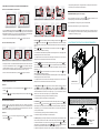
1.3 FASTENING THE STEALTH 3X CHRONOTHERMOSTAT
SCREWS SUPPLIED
MASONRY
TOP VIEW
PROGRAMMABLE THER-
MOSTAT
STEALTH 3X
CONNECTOR
ADAPTER
FOR BOX E503
SCREW SCREW
Fig. 4
Fig. 6 Fig. 8Fig. 7
Fig. 5
6. ERROR REPORTING (appears on the display)
E0: Accompanied by the ashing of the symbol , it indicates the absence of RF
(Radio frequency) communication with the system control unit.
E1: The MASTER is not assigned to any Zone chronothermostat.
E2: Actuator (motor) damper or grid not congured correctly.
E3: No communication between the control unit and the motor. Check the wiring and
power cables again or check that the motor is not faulty (contact the installer or techni-
cal assistance if necessary). (Fig.15)
Fig.9
Fig.12
Fig.10
Fig.13
Fig.11
Fig.14
F1
F3
F2
FA
de
-F
opening/closing of the dampers. Fan regulation does not modify the head curves set
at the factory by the manufacturer of the ducted unit
-
 1
1
-
 2
2
-
 3
3
-
 4
4


Tecnosystemi STEALTH 3X built-in wired backlit programmable thermostat Manuale del proprietario
- Tipo
- Manuale del proprietario
in altre lingue
Documenti correlati
-
Tecnosystemi DISCOVERY 3X wall-mounted backlit programmable thermostat Manuale del proprietario
-
-
-
-
-
Altri documenti
-
CAME TH/700 Guida d'installazione
-
-
-
-
-
CAME TH/500 Guida d'installazione
-
Giacomini K492T Istruzioni per l'uso
-
 Olimpia Splendid kit - B0685 Built-in control kit - B0686 Wall thermostat - B0736 Manuale utente
-
Bticino HC4451 Istruzioni per l'uso
-
