Hangar 9 HAN2890 Manuale del proprietario
- Categoria
- Giocattoli telecomandati
- Tipo
- Manuale del proprietario

Fokker D.VII 30cc–60cc
Instruction Manual
Bedienungsanleitung
Manuel d’utilisation
Manuale di Istruzioni

2EN
NOTICE
All instructions, warranties and other collateral documents are subject to change at the sole discretion of Horizon
Hobby, LLC. For up-to-date product literature, visit horizonhobby.com and click on the support tab for this product.
Age Recommendation: Not For Children Under 14 Years. This Is Not A Toy.
SAFETY WARNINGS AND PRECAUTIONS
Read and follow all instructions and safety precautions before use. Improper use can result in fi re, serious injury and
damage to property.
Components
Use only with compatible components. Should any compatibility questions exist, please refer to the product
instructions, component instructions or contact the appropriate Horizon Hobby offi ce.
Flight
Fly only in open areas to ensure safety. It is recommended fl ying be done at radio control fl ying fi elds. Consult local
ordinances before choosing a fl ying location.
Propeller
If using the motor powered option, always keep loose items that can become entangled in the propeller away from the
prop. This includes loose clothing or other objects such as pencils and screwdrivers. Keep your hands away from the
propeller as injury can occur.
Batteries
Always follow the manufacturer’s instructions when using and disposing of any batteries. Mishandling of Li-Po
batteries can result in fi re causing serious injury and damage.
Small Parts
This kit includes small parts and should not be left unattended near children as choking and serious injury could result.
MEANING OF SPECIAL LANGUAGE
The following terms are used throughout the product literature to indicate various levels of potential harm when
operating this product:
WARNING: Procedures, which if not properly followed, create the probability of property damage, collateral damage,
and serious injury OR create a high probability of superfi cial injury.
CAUTION: Procedures, which if not properly followed, create the probability of physical property damage AND a
possibility of serious injury.
NOTICE: Procedures, which if not properly followed, create a possibility of physical property damage AND a little or
no possibility of injury.
WARNING: Read the ENTIRE instruction manual to become familiar with the features of the product before
operating. Failure to operate the product correctly can result in damage to the product, personal property and
cause serious injury.
This is a sophisticated hobby product. It must be operated with caution and common sense and requires some basic
mechanical ability. Failure to operate this Product in a safe and responsible manner could result in injury or damage
to the product or other property. This product is not intended for use by children without direct adult supervision. Do
not attempt disassembly, use with incompatible components or augment product in any way without the approval of
Horizon Hobby, LLC. This manual contains instructions for safety, operation and maintenance. It is essential to read and
follow all the instructions and warnings in the manual, prior to assembly, setup or use, in order to operate correctly and
avoid damage or serious injury.
SAFE OPERATING RECOMMENDATIONS
• Inspect your model before every fl ight to ensure it is airworthy.
• Be aware of any other radio frequency user who may present an interference problem.
• Always be courteous and respectful of other users in your selected fl ight area.
• Choose an area clear of obstacles and large enough to safely accomodate your fl ying activity.
• Make sure this area is clear of friends and spectators prior to launching your aircraft.
• Be aware of other activities in the vicinity of your fl ight path that could cause potential confl ict.
• Carefully plan your fl ight path prior to launch.
• Abide by any and all established AMA National Model Aircraft Safety Code.
BEFORE STARTING ASSEMBLY
• Remove parts from bag.
• Inspect fuselage, wing panels, rudder and stabilizer for damage.
• If you fi nd damaged or missing parts, contact your place of purchase.
• Charge transmitter and receiver batteries.
• Center trims and sticks on your transmitter.
• For a computer radio, create a model memory for this particular model.
• Bind your transmitter and receiver, using your radio system’s instructions.
NOTICE: Rebind the radio system once all control throws are set. This will keep the servos from moving to their
endpoints until the transmitter and receiver connect. It will also guarantee the servo reversal settings are saved in
the radio system.
FAA INFORMATION
If you own this product, you may be required to register with the FAA.
For up-to-date information on how to register with the FAA, please visit https://registermyuas.faa.gov/.
For additional assistance on regulations and guidance on UAS usage, visit knowbeforeyoufl y.org/.

3 EN
Fokker D.VII 30–60cc ARF
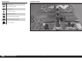
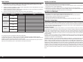
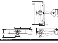
SPECIFICATIONS LARGE PARTS LAYOUT
87.0 in (2209.8 mm)
2430 sq in (156.8 dm2) Total
72 in (1828.8 mm)
25–28 lbs (11.4–12.7 kg)
2-Stroke Gas: 30cc–60cc
Electric Power: 30cc-50cc Equivalent
4-channel (or greater) with 6 servos
7
11
/
16
inches (195mm)

4EN
REQUIRED ADHESIVES
Description
15-minute epoxy
30-minute epoxy
Thin CA
Medium CA
Threadlock, low and high strength
Part # Description
EVOA100 Optical Ignition Kill Switch
SPMAS3000 AS3000 AS3X Stabilization Module
SPMSA6320 A6320 H-T/H-S Brushless HV Servo
SPMSA6380 A6380 H-T/H-S Digital HV Servo
OPTIONAL PARTS
Part # Description
HAN289001 Fuselage & Hatch
HAN289002 Top Hatch
HAN289003 Lower Wing, Left
HAN289004 Lower Wing, Right
HAN289005 Top Wing, Left
HAN289006 Top Wing, Right
HAN289007 Top Center, Wing
HAN289008 Horizontal Stabilizer & Elevator
HAN289009 Fin & Rudder
HAN289010 Cowling & Side Panels
HAN289011 Hardware
HAN289012 Metal Wing Strut Set
HAN289013 Scale Detail Set
HAN289014 Pushrod Set
HAN289015 1/4-Scale WWI Pilot Figure
HAN289016 Electric Motor Box
HAN289017 Tail Skid & hardware
HAN289018 8-inch WWI Wheels, Pair
HAN289019 Fuel Tank, 600cc
HAN289020 Metal U/C & Axle
HAN289021 Aluminum Wing Tubes
HAN289022 Decal Sheet
HAN289023 Lower U/C Wing
HAN289024 Wing Transport Cradle
REPLACEMENT PARTS
TABLE OF CONTENTS
Notice ......................................................................................................................................................................2
Meaning of Special Language ..................................................................................................................................2
Safety Warnings and Precautions .............................................................................................................................2
Safe Operating Recommendations ...........................................................................................................................2
Before Starting Assembly .........................................................................................................................................2
FAA Information .......................................................................................................................................................2
Specifi cations ..........................................................................................................................................................3
Large Parts Layout ...................................................................................................................................................3
Replacement Parts ...................................................................................................................................................4
Optional Parts ..........................................................................................................................................................4
Required Adhesives .................................................................................................................................................4
Required for Completion, Gas Engine Installation......................................................................................................5
Required for Completion, Electric Motor Installation .................................................................................................5
Tools Required .........................................................................................................................................................6
Removing Wrinkles ..................................................................................................................................................6
Building Precautions ................................................................................................................................................6
Transportation and Storage ......................................................................................................................................6
Replacement Covering .............................................................................................................................................6
Nose Weight ............................................................................................................................................................6
Checking Blind Nuts.................................................................................................................................................6
Control Horn Installation ...........................................................................................................................................7
Aileron Servo Installation .......................................................................................................................................10
Attach the Fin to the Stabilizer ...............................................................................................................................12
Tail Skid Installation ...............................................................................................................................................14
Cockpit Detail Installation .......................................................................................................................................15
Stabilizer and fi n installation ..................................................................................................................................17
Rudder and Elevator Servo Installation ...................................................................................................................19
Tail Bracing Installation ..........................................................................................................................................21
Landing Gear Installation .......................................................................................................................................22
Electric Motor Installation .......................................................................................................................................26
Gas Engine Installation ...........................................................................................................................................28
Cowling Installation................................................................................................................................................30
Receiver Installation ...............................................................................................................................................33
Wing Installation ....................................................................................................................................................34
Center of Gravity ....................................................................................................................................................35
Control Throws ......................................................................................................................................................36
Prefl ight Checklist ..................................................................................................................................................36
Daily Flight Checks ................................................................................................................................................36
Limited Warranty ...................................................................................................................................................36
Warranty and Service Contact Information .............................................................................................................37
Compliance Information for the European Union .....................................................................................................37
Instructions for Disposal of WEEE by Users in the European Union ..........................................................................37
AMA National Model Aircraft Safety Code ..............................................................................................................38

5 EN
Fokker D.VII 30–60cc ARF
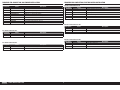
REQUIRED FOR COMPLETION, GAS ENGINE INSTALLATION REQUIRED FOR COMPLETION, ELECTRIC MOTOR INSTALLATION
# Required Part # Description
1 SPMAR12310T AR12310T 12-Channel PowerSafe Telemetry Receiver
1 DUB800 Tygon Gas Tubing,3’ Large
2 EVOA112 Evolution 3 Wire Ignition/RX Switch
3 SPMB4000LPRX 4000mAh 2S 7.4V LiPo Rx Battery
1 HAN116 Fuel Filler with "T" & Overfl ow Fitting
2 SPM9530 Spektrum 3-Wire Switch Harness
2 SPMA3002 Heavy-Duty Servo Extension 9-inch
1 SPMA3006 Heavy-Duty Servo Extension 36-inch
6
SPMSA6380 A6380 H-T/H-S Digital HV Servo
Gas Powered Version, All
Gas Powered Version, 30cc
Gas Powered Version, 60cc
Electric Powered Version, All
Electric Powered Version, 30cc
Electric Powered Version, 60cc
# Required Part # Description
1 EVOE33GX 33GX 33cc (2.00) Gas/Petrol Eng
1 APC18080W Competition Propeller, 18 x 8W
# Required Part # Description
1 EVOE62GX 62GX 62cc Gas/Petrol Engine
1 EVOM6 62cc Inverted Wraparound Muffl er
# Required Part # Description
1 GPMM2260 ElectriFly 160 Amp HV 6S-14S Prog B
2 SPMA3002 Heavy-Duty Servo Extension 9-inch
2 SPMA3006 Heavy-Duty Servo Extension 36-inch
5 SPMSA6380 A6380 H-T/H-S Digital HV Servo
1 CSEM1530 Castle Creations CC BEC 2.0 BEC WP Voltage Regulator
1 SPMAR9350 AR9350 9-Channel AS3X Receiver
# Required Part # Description
1 GPMG4796 Rimfi re 1.70 63-62-200 Outrunner
1 APC20010E Electric Propeller, 20 x 10E
4 KXSB50005S30 F-Tek 5000mAh 5S 18.5V 30C, EC5
# Required Part # Description
1 GPMG4805 Rimfi re 65cc Outrunner
1 24 x 10
2 SPMX70006S30 22.2V 7000 mAh 6S 30C Smart LiPo, IC5

6EN
REMOVING WRINKLES
The covering of your model may develop wrinkles during shipping and will require the use of a heat gun (HAN100)
and covering glove (HAN150) or covering iron (HAN101) with a sealing iron sock (HAN141) to remove them. Use
caution while working around areas where the colors overlap to prevent separating the colors. Avoid using too much
heat, which could separate the colors. Placing a cool damp cloth on adjacent colors will also help in preventing the
separation of the colors while removing wrinkles.
BUILDING PRECAUTIONS
Prepare the work surface prior to beginning the build. The surface should be soft and free of any sharp objects. We
recommend resting the airframe parts on a soft towel or pit mat to prevent scratching or denting the surface of the
aircraft.
TRANSPORTATION AND STORAGE
When transporting and storing your model, you will need a minimum of 80 inches (2m) in length, and 18 inches
(46cm) in height to accommodate the size of the fuselage. We also recommend the use of wing and stabilizer bags to
help protect these surfaces during transport and storage. The control horns and linkages can cause damage to other
surfaces even when placed in storage bags. Always transport and store the wings and stabilizer so the linkages do not
contact other panels to prevent damage.
REPLACEMENT COVERING
Your model is covered with UltraCote
®
fi lm in the following colors. If repairs are required, order these coverings to
make those repairs.
White HANU870
Black HANU874
Red HANU871
We have found the Testors Red Paint Marker (TES2503C) matched the red used on the Fokker D.VII and can be used for
touch-up on all the painted parts.
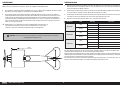
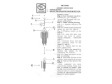
NOSE WEIGHT
To maintain the scale outline of your model, it will require the addition of nose weight to properly balance. Testing
has been performed on all power options. Using a heavier engine or motor will help in reducing the amount of weight
required. Make sure to use proper throttle management when fl ying with these larger and more powerful options. Our
test aircraft with the recommended Evolution
®
62cc engine and muffl er, and receiver and ignition batteries on either
side of the fuel tank required 1
1
/
2
lbs (680g) of nose weight. Using the Evolution 33GX may require the addition of up
to 6 lbs (2.7kg) to proerly balance your model. This may vary from plane to plane. Add this weight as far forward in the
fuselage as possible to reduce the amount required to balance. This weight must be secure so it does not come loose
in fl ight, causing an unsafe model which could result in the loss of the aircraft.
CHECKING BLIND NUTS
When building the aircraft, you will be required to thread machine screws into blind nuts. We recommend pre-threading
the screws to make sure the blind nuts are clear of any debris. If the screws do not thread in easily, clear the threads
using the appropriate tap and tap handle.
TOOLS REQUIRED
Description
Balancing stand
Clamps
Crimping tool
Drill and tap set, metric
Drill bit set
Epoxy brushes
Felt-tipped pen
Flat fi le
Hemostats
Hex wrench set, metric
Hobby knife with #11 blade
Hobby scissors
Hook and loop straps
Hook and loop tape
Isopropyl alcohol
Locking pliers
Low-tack tape
Mixing sticks
Needle nose pliers
Nut driver set, metric
Paper towels
Pencil
Phillips screwdriver: #0, #1, #2
Pin vise
Pliers
Razor saw
Rotary tool
Ruler
Sanding bar
Sanding drum for rotary tool
Sandpaper
Scissors
Side cutters
Square
Tap handle
Tapered reamer
Tie wraps
Toothpicks
T-pins
Vinal tape, red
Wire stripper

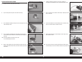
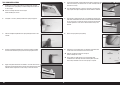
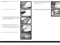
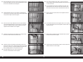
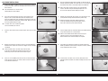
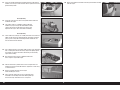
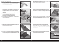
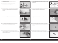
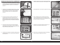
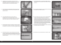
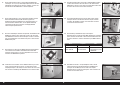
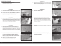
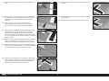
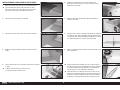
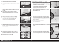
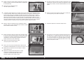
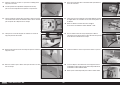
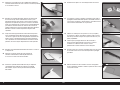
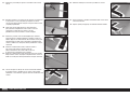
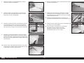
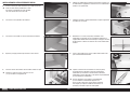
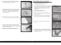
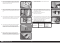
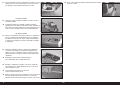
CONTROL HORN INSTALLATION
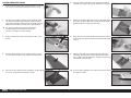
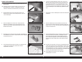
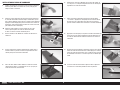
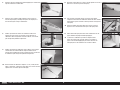
1. Check the fi t of the clevis to each of the control horns. Use a pin vise
and 1/16-inch (1.5mm) drill bit to enlarge the hole if necessary.
2. Use medium-grit sandpaper to lightly sand the red aileron control
horn where it fi ts into the aileron. Clean the sanded area using a
paper towel and isopropyl alcohol to remove any debris or oils. This
provides the surface texture necessary for the epoxy to bond to.
Use tape on the painted area to help prevent removing
the exposed portion of the control horn. Remove the
tape once the control horn has been sanded.
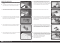
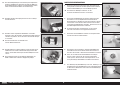
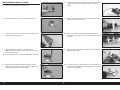
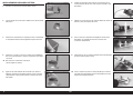
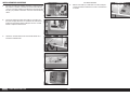
4. Test fi t the aileron control horn in the slot in the aileron. It may be
necessary to trim the opening in the aileron to fi t the control horn.
5. Place low-tack tape around the aileron control horn. The tape should
be 1/32-inch (1mm) from the control horn as shown.
3. Remove the aileron from the wing. Set the hinges aside in a safe
location.
6. Check that the horn is 90-degrees to the surface of the aileron. If
not, lightly trim the hole in the aileron to reposition the control horn.
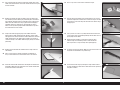
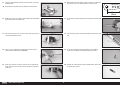
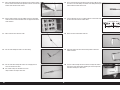
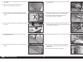
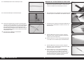
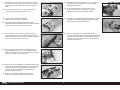
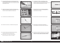
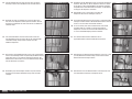
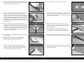
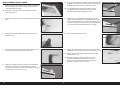
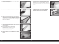
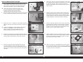
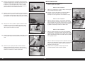
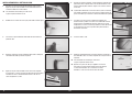
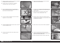
7. Remove the control horn. Mix 10g of 15-minute epoxy. Apply epoxy
to the slot in the aileron. Make sure the epoxy gets into the slot for a
good bond between the aileron and control horn.
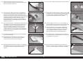
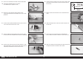
9. Before the epoxy fully cures, remove the tape from around the
control horn. This will allow the epoxy to fl ow around the control
horn, creating a small fi llet between the control horn and surface for
a fi nished look and secure bond.
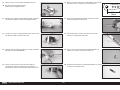
10. Insert the rudder control horn in the rudder. The tabs on the horn will
rest against the rudder.
8. Apply epoxy to the area of the control horn that fi ts into the slot. Use
enough epoxy so the control horn will be fully bonded to the control
surface.
7 EN
Fokker D.VII 30–60cc ARF

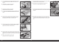
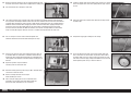
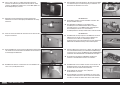
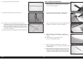
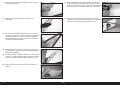
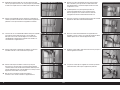
11. Use a felt-tipped pen to mark the control horn on both sides of the
rudder. This will indicate the area of the control horn where the paint
must be removed.
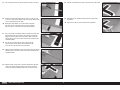
12. Remove the control horn from the rudder. Place tape against the
lines drawn to prevent removing any unwanted paint. Use medium-
grit sandpaper to lightly sand the control horn where it fi ts into the
udder. Clean the sanded area using a paper towel and isopropyl
alcohol to remove any debris or oils. This provides the surface
texture necessary for the epoxy to bond to. Remove the tape once
the control horn has been sanded.
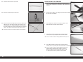
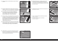
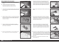
14. Remove the elevator from the stabilizer. Set the hinges aside in a
safe location.
Place a piece of tape on the top of elevator and stabilizer so
they can be oriented in the same direction later in the manual.
15. Install the white elevator control horns to complete the control horn
installation. Follow the same procedure as the aileron control horns
to install the elevator control horns.
13. Prepare the rudder by applying tape to the rudder around the
opening for the rudder control horn. Mix 10g of 15-minute epoxy
and apply it to the sanded area of the rudder control horn. Insert the
rudder control horn in the rudder. Check to make sure the horn is
centered correctly in the rudder. Allow the epoxy to fully cure before
proceeding.
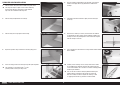
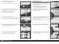
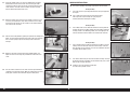
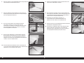
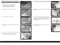
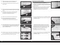
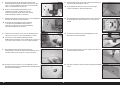
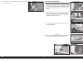
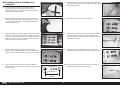
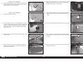
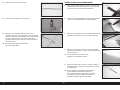
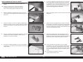
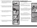
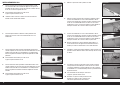
16. Place a T-pin in the center of each of the three hinges.
17. Slide the hinges into position in the aileron with the T-pin resting
against the edge of the control surface. Center the hinge in the slot
and mark the center of the hinge on the bevel of the aileron using a
felt-tipped pen.
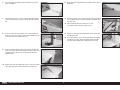
19. Fit all three hinges to the aileron. Make sure to center the slot in the
hinge with the hole drilled in the previous step.
20. Fit the aileron to the wing by inserting the hinges into the slots in
the wing. Position the aileron so the aileron does not rub against the
wing when it moves.
18. Use a pin vise and 1/16-inch (1.5mm) drill bit to drill a hole in the
center of each hinge slot marked previously. Drill the hole 1/4-inch
(6mm) deep into the wood.
Drilling this hole provides a tunnel for the CA to fully wick
into the hinge and surrounding surface. Failure to drill this
hole may result in a hinge that may not be glued properly.
8EN

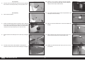
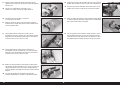
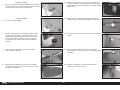
21. Use a felt-tipped marker to mark the slot of the hinge on the wing.
22. Remove the aileron and hinges from the wing. Use a pin vise and
1/16-inch (1.5mm) drill bit to drill a hole at each mark. Drill the hole
1/4-inch (6mm) deep into the wood.
Drilling this hole provides a tunnel for the CA to fully wick
into the hinge and surrounding surface. Failure to drill this
hole may result in a hinge that may not be glued properly.
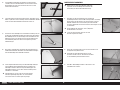
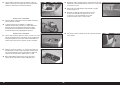
24. Apply thin CA to the bottom of each of the hinges. Make sure to fully
soak the hinges so the CA can wick into the hinge and bond to the
surrounding wood.
25. Allow the CA to cure for 10 to 15 minutes. Gently pull on the fi xed
surface and control surface to make sure the hinges are glued
securely. If not, apply additional CA to secure each of the hinges.
23. Use a paper towel and isopropyl alcohol to remove any marks from
the wing and aileron. Fit the hinges and aileron back in position.
Apply thin CA to the top of each of the hinges. Make sure to fully
soak the hinges so the CA can wick into the hinge and bond to the
surrounding wood.
Use thin CA so it wicks into the hinge. A thicker CA will
not wick into the hinge properly. Do not to allow the CA
to run over the covering on the wing and aileron.
26. Move the aileron through its range of travel to break in the hinges.
27. Check both the up and down movement of the hinges before
proceeding.
Repeat this section for the remaining aileron installation.
9 EN
Fokker D.VII 30–60cc ARF

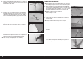
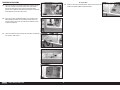
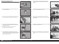
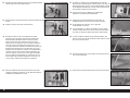
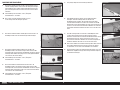
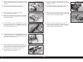
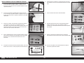
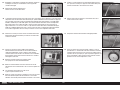
AILERON SERVO INSTALLATION
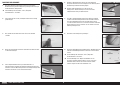
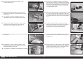
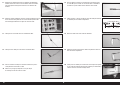
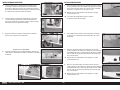
1. Remove the aileron servo cover from the wing.
2. Tape the string to the wing so it won’t fall into the wing.
4. Use a #2 Phillips screwdriver to thread the M3 x 10 self-tapping
screws into the holes. Remove the screws before proceeding to the
next step.
Do not press down excessively on the screw
as it could damage the structure.
5. Apply a small amount of thin CA to harden the threads made in the
previous step. Allow the CA to fully cure before installing the aileron
servo cover.
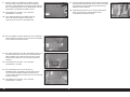
3. Use a toothpick or hobby knife to puncture the covering for the servo
cover mounting screws.
6. Install the grommets and eyelets in the servos. Follow any
instructions included with the servo. Prepare both aileron servos.
7. Place a servo arm on the aileron servo to help in aligning the servo
to the servo cover.
9. Mark the locations for the servo mounting screws using a pencil,
then remove the servo.
10. Use a drill and a 5/64-inch (2mm) drill bit to drill the holes for the
servo mounting screws in the locations marked in the previous step.
8. Fit the servo between the servo mounting tabs in the aileron servo
tray. The servo arm will be centered in the slot.
10EN

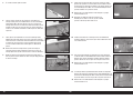
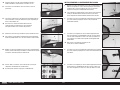
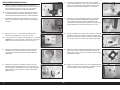
11. Thread a servo mounting screw into each of the holes in the servo
mounting holes.
Do not skip this step. Doing so may damage the servo mounts.
12. Remove the screws, then apply a small amount of thin CA to harden
the threads made in the previous step.
14. Secure a 9-inch (230mm) servo extension to the servo using a
commercially available retainer (SPMA3054).
15. Center the servo, then secure the servo arm so it is perpendicular
to the servo center line. Use side cutters to remove any unneeded
servo arms.
13. After the CA has fully cured, secure the servo to the cover using the
screws provided with the servo.
16. When attaching the linkage to the aileron servo arm, use the hole in
the arm that is 5/8-inch (16mm) from the center of the arm.
17. Tie or tape the string located inside the wing to the end of the servo
lead.
19. Secure the servo to the wing using four M3 x 10 self-tapping
screws. Use a #2 Phillips screwdriver to tighten the screws.
20. Remove the clevises from the aileron pushrod. Slide a retainer over
the barrel of the clevises.
18. Use the string to pull the servo lead through the wing and out at the
root.
11 EN
Fokker D.VII 30–60cc ARF
5/8 inch
(16mm)

21. Thread the clevises back on the pushrod.
22. Attach the aileron linkage to the servo arm.
23. Connect the servo to the radio system to center the aileron servo.
Loosen the nuts, then adjust the linkage so the aileron is in the
neutral position. Place a drop of thread lock on the linkage near
the clevises. Tighten the nuts over the thread lock and against the
clevises, then slide the retainers over the forks of the clevises.
Repeat this section for the remaining aileron servo installation.
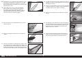
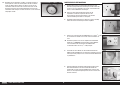
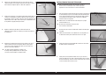
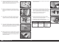
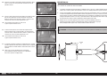
ATTACH THE FIN TO THE STABILIZER
1. Use a square and felt-tipped pen to draw a line on the top of the
stabilizer from the front and rear edges of the slot on the top of the
stabilizer.
2. Fit the fi n to the stabilizer. Use a felt-tipped pen to mark the forward
tip of the fi n on the stabilizer.
4. Use a hobby knife with a new #11 blade to carefully trim the
covering 1/16-inch (1.5mm) below the line drawn on the fi n.
Use care not to cut into the underlying wood, weakening the fin.
5. Use a hobby knife with a new #11 blade to carefully trim the
covering 1/16-inch (1.5mm) inside the lines drawn on the stabilizer.
Use care not to cut into the underlying wood, weakening the
stabilizer. Apply a bead of thin CA into the area where the
film was cut away to seal the edge of the covering, as well
as applying thin CA into any possible cut into the wood.
3. Use a felt-tipped pen to mark the edge of the stabilizer on the
bottom of the fi n where it fi ts into the stabilizer.
12EN

6. Use a paper towel and isopropyl alcohol to remove any lines from
the fi n and stabilizer.
7. Use low-tack tape to secure a piece of plastic (packaging from the
parts is suitable) over the area on the fuselage where the stabilizer
fi ts.
9. Check the fi t of the stabilizer and fi n to the fuselage. The rear edge
of the fi n must align with the rear edge of the fuselage. Lightly sand
the bottom of the fi n where it fi ts in the stabilizer to correct any
positioning errors.
10. Remove the fi n from the stabilizer. Mix 1/4 oz. (7.5mL) of 30-minute
epoxy. Apply epoxy to the exposed wood using an epoxy brush.
8. Check the fi t of the fi n to the stabilizer. Use a square to make sure
the fi n fi ts square to the stabilizer. Lightly sand the bottom of the fi n
if necessary to correct any alignment issues.
11. Apply epoxy to the exposed wood on the bottom of the fi n using an
epoxy brush.
12. Fit the fi n in position. Use a square to check the alignment of the fi n
to the stabilizer. Use low-tack tape to hold the fi n in position while
the epoxy cures.
Check the position of the fin to make sure it is still
square to the stabilizer while the epoxy is curing.
13. Remove any epoxy from the fi n and stabilizer using a paper towel
and isopropyl alcohol.
The fin and stabilizer can be carefully removed from the fuselage.
If removed, use a paper towel and isopropyl alcohol to remove
any epoxy from the bottom of the stabilizer where the fin fits.
13 EN
Fokker D.VII 30–60cc ARF

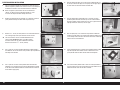
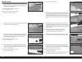
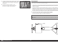
TAIL SKID INSTALLATION
1. Remove the rear hatch cover from the fuselage. Apply a drop of
thread lock on the spring fi tting. Thread the fi tting into the blind nut
in the fuselage.
Refer to checking the blind nuts on Page 6
before installing the screws.
2. Straighten a 3/4-inch (19mm) section of the spring using pliers.
4. Bend the straightened portion of the spring back around and loop
the wire back around the spring to secure the spring to the skid.
5. Apply a drop of thread lock on the two M3 x 12 socket head screws.
Attach the tail skid bracket to the fuselage using the two screws and
two M3 washers. Tighten the screws using a 2.5mm hex wrench.
3. Slide the straightened portion of the spring through the hole in the
tail skid.
6. Fit the skid in position, checking the fi t of the skid in the bracket. The
skid must fi t freely in the bracket so it can move. Carefully bend the
bracket if necessary.
The skid should ideally be a snug fit in this slot in the fuselage. It
may require some light sanding of this slot to allow the skid to fit.
7. Slide an M3 x 20 socket head cap screw through the bracket and
skid. Slide an M3 washer on the screw, then thread the M3 locknut
on the screw. Use a 2.5mm hex wrench and 5.5mm nut driver. Do
not over-tighten the screw, as the skid must move freely in the
bracket.
9. Replace the rear fuselage hatch. Use four M3 x 10 button head
screws and a 2mm hex wrench to secure the cover.
Refer to checking the blind nuts on Page 6
before installing the screws.
Place a drop of canopy glue on each screw before their
installation. This will keep them from vibrating loose yet leave
them easily removable if access to the spring is required.
8. Attach the spring to the spring fi tting.
14EN

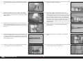
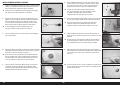
COCKPIT DETAIL INSTALLATION
1. Remove the two thumb screws that secure the canopy hatch to the
fuselage.
The nylon bolt can be shortened to make securing the canopy hatch
easier. A metal fastener can also be substituted (not included).
2. Lift the canopy hatch from the fuselage at the rear. Slide the hatch
back and remove it from the fuselage. Set it aside in a safe location.
4. Fit the ammunition to the gun rails. The ammunition will align with
the top edge of the rails and fall straight into the rails as shown.
5. Slide a large M3 washer on an M3 x 25 socket head screw. Slide the
screw from the bottom of the forward cockpit fl oor.
3. Use a hobby knife and #11 blade as well as hobby scissors to trim
the ammunition. Leave the ammunition wide so it can be trimmed
down to fi t the rails. Trim both sets of ammunition.
6. Slide the standoff with the hole only through the center over the
screw, then place a mounting bracket on the screw. Secure the
hardware with an M3 locknut. Tighten the hardware using a 2.5mm
hex wrench and 5.5mm nut driver. Leave the hardware slightly loose
so it can be positioned when the rear mounts are installed.
7. Repeat the previous steps to install the second gun mount.
9. Locate the two standoffs with the perpendicular holes. Attach the
mounting brackets to the standoffs using two M3 x 10 button head
screws and two M3 washers. Leave the screws slightly loose so the
mounts can be positioned later in this section of the manual.
10. Slide an M3 lock washer on an M3 x 25 socket head cap screw.
Slide the screw through the standoff, then through the hole support
bar. Thread the screw into the blind nut that has been installed in the
cockpit. Make sure not to cross thread the screw and damage the
blind nut. Leave the screws loose at this time.
Refer to checking the blind nuts on Page 6
before installing the screws.
8. Fit the rear support bar in the cockpit. The ends are angled to match
the shape of the fuselage sides. If it does not fi t without binding,
lightly fi le the ends so it fi ts without binding against the inside edges
of the fuselage hatch.
15 EN
Fokker D.VII 30–60cc ARF

11. Use a straight edge to check the alignment between the front and
rear mounts. Once aligned, the hardware for the mounts can be
tightened.
Leave the M3 x 35 socket head screws loose
that attach the mounts to the support bar.
Read through the following steps and work
through them before using any adhesives.
12. Use contact or slow setting adhesive to glue the ammunition rail in
the cockpit. The exact position will be adjusted once the guns are
secure.
14. Attach the right gun to the rear mount using an M3 x 25 socket head
cap screw and M3 locknut. Use hemostats to hold the nut while
tightening the screw with a 2.5mm hex wrench.
15. Repeat the previous steps to install the left gun to the mounts. Once
both guns are in place, tighten the screws for the gun mounts at the
support bar. Glue the gun sights to the machine guns using medium
CA.
The gun sights are optional and can be easily
damaged if the hatch is repeatedly removed.
13. Attach the right gun to the front mount using an M3 x 25 socket
head cap screw and M3 locknut. Use hemostats to hold the nut
while tightening the screw with a 2.5mm hex wrench.
16. Slide the ammunition rails so they are tight against the guns. Allow
the adhesive to fully cure before proceeding.
A black marker can be used to touch up any areas on the
guns where the underlying wood may be exposed.
17. Use contact adhesive to glue the pilot in the cockpit. Set the cockpit
aside to allow the adhesive to fully cure while continuing the build of
the model.
18. When fi tting or removing the top hatch, be sure to angle the hatch
up against the trailing edge of the top wing center section. This way
the delicate gun sights do not get knocked off as the hatch is slid
back.
16EN

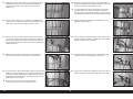
STABILIZER AND FIN INSTALLATION
1. Slide the shorter wing tube into the bottom wing tube socket.
The wing tube may be a tight fit in the socket. Polishing
the wing tube with fine sand paper or steel wool will
help ease the installation of the wing tube.
2. Slide the wing into position on the fuselage.
4. Repeat the previous steps to attach the remaining wing panel.
5. Secure the wing panels to the fuselage using two nylon wing bolts.
The nylon bolt can be shortened to 1
3
/
8
inches
(55mm) to make securing the wing easier.
3. Slide the wing so it is tight against the fuselage.
6. Place the stabilizer into position on the fuselage, check that the
stabilizer rest tightly with no gap between the stabilizer and
fuselage.
7. Check both sides of the stabilizer. Lightly sand the fuselage if
necessary.
9. Use a felt-tipped pen to transfer the fuselage outline onto the bottom
of the stabilizer.
10. Carefully cut the covering 1/8 inch (3mm) inside the line drawn
on the bottom of the stabilizer to remove the covering from the
center of the stabilizer. Use care not to cut into the underlying wood,
weakening the stabilizer.
Use care not to cut into the underlying wood, weakening the
stabilizer. Apply a bead of thin CA into the area where the
film was cut away to seal the edge of the covering, as well
as applying thin CA into any possible cut into the wood.
8. Stand back 8-10 feet (2-3 meters) and check that the stabilizer
is aligned with the wing. Lightly sand the stabilizer saddle on the
fuselage to correct any misalignment. The fi n will also be aligned
with the fuselage center line.
17 EN
Fokker D.VII 30–60cc ARF

11. Remove any lines from the stabilizer using a paper towel and
isopropyl alcohol.
12. Use a covering iron to seal the covering to the stabilizer.
14. Mix 20g of 30-minute epoxy. Use an epoxy brush to apply epoxy to
the exposed wood on the bottom of the stabilizer.
We strongly suggest 30-minute epoxy for this task to allow time to
properly install and align the stabilizer to the fuselage and wings.
15. Apply epoxy to the exposed wood on the top of the fuselage.
13. Check that the bottom of the stabilizer is smooth and level. If not,
use low-tack tape to protect the covering, then use a sanding bar to
sand the bottom of the stabilizer. Remove the tape and check that
the covering is still secured to the stabilizer.
16. Fit the stabilizer into position. Remove any epoxy from the fuselage
and stabilizer using a paper towel and isopropyl alcohol. There will
be excess epoxy, so use a few paper towels to properly remove it
from the outside of the model.
17. Use low-tack tape to hold the stabilizer in position while the epoxy
cures. Check the alignment periodically during the curing process.
18EN

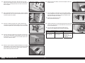
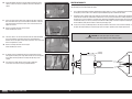
RUDDER AND ELEVATOR SERVO INSTALLATION
1. Hinge the rudder to the fi n and fuselage using the techniques from
hinging the ailerons. Use a hobby knife with a #11 blade to set the
gap between the balance tab and top of the fi n.
2. Hinge the elevators to the stabilizer using the techniques from
hinging the ailerons. Use a hobby knife with a #11 blade to set the
gap between the balance tabs and stabilizer tips.
5. When attaching the linkage to the elevator servo arm, use the hole
in the arm that is 5/8-inch (16mm) from the center of the arm.
3. Prepare and install the rudder and elevator servos in the fuselage.
The process is the same as the aileron servo installation. The center
servo operates the rudder, while the outer servos operate the
elevators. The servo output for all servos will face the front of the
fuselage.
6. Remove the clevis and nut from one end of the elevator pushrod.
Slide the elevator pushrod into the pushrod tube.
7. Attach the clevis to the elevator servo arm.
9. Repeat the process of installing the elevator pushrod and servo arm
for the remaining elevator servo.
10. Make sure to adjust the pushrod when connecting the clevis to the
control horn at the elevator.
8. Thread the nut and clevis back on the elevator pushrod. Adjust the
clevis at the servo and control horn so the elevator is centered when
the clevis is attached to the elevator control horn.
4. Use the radio system to center the elevator servo. Install the servo
arm so it will be 90 degrees to the pushrod. Remove any unused
arms from the servo arm using side cutters.
19 EN
Fokker D.VII 30–60cc ARF
5/8 inch
(16mm)

11. Place a drop of thread lock on the linkage near the clevises. Tighten
the nuts over the thread lock and against the clevises, then slide the
retainers over the forks of the clevises.
12. Use the radio system to center the rudder servo. Place the rudder
servo arm on the servo so two of the arms are perpendicular to the
servo centerline.
14. Pass the cable through the hole in the cable fi tting.
15. Pass the cable back through the sleeve. Use crimping pliers to
secure the sleeve to the cable.
Use caution to not press too hard and cut the
crimp instead of securing it to the wire.
13. Slide a sleeve on one end of the cable.
16. Place a retainer over the barrel of the clevis. Thread an M3 nut, then
the clevis, on the cable fi tting. The threads of the fi tting will barely be
visible between the forks of the clevis.
17. Use the holes that are 5/8 inch (16mm) from the center of the servo
to attach the clevises for the rudder cables.
19. Repeat the process to attach the remaining rudder cable to the
rudder servo arm.
20. Pass the cables through the tubes inside the fuselage and retrieve
them at the rear of the fuselage. Removing the rear fuselage cover
will make retrieving the cable easier.
18. Attach the cable to the rudder servo arm.
20EN
5/8 inch
(16mm)
5/8 inch
(16mm)
La pagina si sta caricando...
La pagina si sta caricando...
La pagina si sta caricando...
La pagina si sta caricando...
La pagina si sta caricando...
La pagina si sta caricando...
La pagina si sta caricando...
La pagina si sta caricando...
La pagina si sta caricando...
La pagina si sta caricando...
La pagina si sta caricando...
La pagina si sta caricando...
La pagina si sta caricando...
La pagina si sta caricando...
La pagina si sta caricando...
La pagina si sta caricando...
La pagina si sta caricando...
La pagina si sta caricando...
La pagina si sta caricando...
La pagina si sta caricando...
La pagina si sta caricando...
La pagina si sta caricando...
La pagina si sta caricando...
La pagina si sta caricando...
La pagina si sta caricando...
La pagina si sta caricando...
La pagina si sta caricando...
La pagina si sta caricando...
La pagina si sta caricando...
La pagina si sta caricando...
La pagina si sta caricando...
La pagina si sta caricando...
La pagina si sta caricando...
La pagina si sta caricando...
La pagina si sta caricando...
La pagina si sta caricando...
La pagina si sta caricando...
La pagina si sta caricando...
La pagina si sta caricando...
La pagina si sta caricando...
La pagina si sta caricando...
La pagina si sta caricando...
La pagina si sta caricando...
La pagina si sta caricando...
La pagina si sta caricando...
La pagina si sta caricando...
La pagina si sta caricando...
La pagina si sta caricando...
La pagina si sta caricando...
La pagina si sta caricando...
La pagina si sta caricando...
La pagina si sta caricando...
La pagina si sta caricando...
La pagina si sta caricando...
La pagina si sta caricando...
La pagina si sta caricando...
La pagina si sta caricando...
La pagina si sta caricando...
La pagina si sta caricando...
La pagina si sta caricando...
La pagina si sta caricando...
La pagina si sta caricando...
La pagina si sta caricando...
La pagina si sta caricando...
La pagina si sta caricando...
La pagina si sta caricando...
La pagina si sta caricando...
La pagina si sta caricando...
La pagina si sta caricando...
La pagina si sta caricando...
La pagina si sta caricando...
La pagina si sta caricando...
La pagina si sta caricando...
La pagina si sta caricando...
La pagina si sta caricando...
La pagina si sta caricando...
La pagina si sta caricando...
La pagina si sta caricando...
La pagina si sta caricando...
La pagina si sta caricando...
La pagina si sta caricando...
La pagina si sta caricando...
La pagina si sta caricando...
La pagina si sta caricando...
La pagina si sta caricando...
La pagina si sta caricando...
La pagina si sta caricando...
La pagina si sta caricando...
La pagina si sta caricando...
La pagina si sta caricando...
La pagina si sta caricando...
La pagina si sta caricando...
La pagina si sta caricando...
La pagina si sta caricando...
La pagina si sta caricando...
La pagina si sta caricando...
La pagina si sta caricando...
La pagina si sta caricando...
La pagina si sta caricando...
La pagina si sta caricando...
La pagina si sta caricando...
La pagina si sta caricando...
La pagina si sta caricando...
La pagina si sta caricando...
La pagina si sta caricando...
La pagina si sta caricando...
La pagina si sta caricando...
La pagina si sta caricando...
La pagina si sta caricando...
La pagina si sta caricando...
La pagina si sta caricando...
La pagina si sta caricando...
La pagina si sta caricando...
La pagina si sta caricando...
La pagina si sta caricando...
La pagina si sta caricando...
La pagina si sta caricando...
La pagina si sta caricando...
La pagina si sta caricando...
La pagina si sta caricando...
La pagina si sta caricando...
La pagina si sta caricando...
La pagina si sta caricando...
La pagina si sta caricando...
La pagina si sta caricando...
La pagina si sta caricando...
La pagina si sta caricando...
La pagina si sta caricando...
La pagina si sta caricando...
La pagina si sta caricando...
La pagina si sta caricando...
La pagina si sta caricando...
-
 1
1
-
 2
2
-
 3
3
-
 4
4
-
 5
5
-
 6
6
-
 7
7
-
 8
8
-
 9
9
-
 10
10
-
 11
11
-
 12
12
-
 13
13
-
 14
14
-
 15
15
-
 16
16
-
 17
17
-
 18
18
-
 19
19
-
 20
20
-
 21
21
-
 22
22
-
 23
23
-
 24
24
-
 25
25
-
 26
26
-
 27
27
-
 28
28
-
 29
29
-
 30
30
-
 31
31
-
 32
32
-
 33
33
-
 34
34
-
 35
35
-
 36
36
-
 37
37
-
 38
38
-
 39
39
-
 40
40
-
 41
41
-
 42
42
-
 43
43
-
 44
44
-
 45
45
-
 46
46
-
 47
47
-
 48
48
-
 49
49
-
 50
50
-
 51
51
-
 52
52
-
 53
53
-
 54
54
-
 55
55
-
 56
56
-
 57
57
-
 58
58
-
 59
59
-
 60
60
-
 61
61
-
 62
62
-
 63
63
-
 64
64
-
 65
65
-
 66
66
-
 67
67
-
 68
68
-
 69
69
-
 70
70
-
 71
71
-
 72
72
-
 73
73
-
 74
74
-
 75
75
-
 76
76
-
 77
77
-
 78
78
-
 79
79
-
 80
80
-
 81
81
-
 82
82
-
 83
83
-
 84
84
-
 85
85
-
 86
86
-
 87
87
-
 88
88
-
 89
89
-
 90
90
-
 91
91
-
 92
92
-
 93
93
-
 94
94
-
 95
95
-
 96
96
-
 97
97
-
 98
98
-
 99
99
-
 100
100
-
 101
101
-
 102
102
-
 103
103
-
 104
104
-
 105
105
-
 106
106
-
 107
107
-
 108
108
-
 109
109
-
 110
110
-
 111
111
-
 112
112
-
 113
113
-
 114
114
-
 115
115
-
 116
116
-
 117
117
-
 118
118
-
 119
119
-
 120
120
-
 121
121
-
 122
122
-
 123
123
-
 124
124
-
 125
125
-
 126
126
-
 127
127
-
 128
128
-
 129
129
-
 130
130
-
 131
131
-
 132
132
-
 133
133
-
 134
134
-
 135
135
-
 136
136
-
 137
137
-
 138
138
-
 139
139
-
 140
140
-
 141
141
-
 142
142
-
 143
143
-
 144
144
-
 145
145
-
 146
146
-
 147
147
-
 148
148
-
 149
149
-
 150
150
-
 151
151
-
 152
152


Hangar 9 HAN2890 Manuale del proprietario
- Categoria
- Giocattoli telecomandati
- Tipo
- Manuale del proprietario
in altre lingue
- English: Hangar 9 HAN2890 Owner's manual
- français: Hangar 9 HAN2890 Le manuel du propriétaire
- Deutsch: Hangar 9 HAN2890 Bedienungsanleitung
Documenti correlati
-
 Hangar 9 HAN4720CR Manuale del proprietario
-
 Hangar 9 HAN2530 Manuale del proprietario
-
 Hangar 9 HAN5260 Manuale del proprietario
-
Evolution 33cc Manuale del proprietario
-
 Hangar 9 HAN4770 Manuale del proprietario
-
 Hangar 9 HAN2370 Manuale del proprietario
-
 Hangar 9 HAN2390 Manuale del proprietario
-
 Hangar 9 HAN4670 Manuale del proprietario
-
 Hangar 9 HAN3185 Manuale del proprietario
-
 Hangar 9 HAN5260B Manuale del proprietario


Altri documenti
-
E-flite SLICK 3D 480 Manuale utente
-
-
Spektrum SPMSA6380 Manuale del proprietario
-
 OK LIGHTING OK-5112H Guida d'installazione
-
Blade BLH4925SC Manuale del proprietario
-
 Next Level f-gt simulator cockpit Manuale utente
-
 Team Orion ORI14150 Manuale utente
-
Rothenberger Power threader SUPERTRONIC 1250 Manuale utente


