
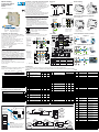
DIN rail mounting,
6 inputs and 2 outputs
digital I/O module
D8 line
Quick Guide • 17/11 • ISTR_Q_D8_1_03_--
viale Indipendenza 56, 27029 - Vigevano (PV)
Tel.: +39 0381 698 71, Fax: +39 0381 698 730
internet site: www.ascontecnologic.com
E-mail: [email protected]
Dimensions
Terminal connectors
99 mm
3.9 in
22.5 mm
0.89 in
6.3 mm
0.25 in
114.5 mm
4.5 in
4 terminal connectors
A
B
C
D
Power supply/
comm.s
connector
Power supply voltage:
24Vac (-25...+12%) or
24Vdc (-15....+25%)
Termi-
nation
plug
Removing the instrument from the DIN rail
Switch the instrument off
12
DIN rail mounting
1
CLICK
2
1 Clip the upper part of the
instrument on the rail;
2 Rotate the instrument
downwards until the click;
1 Lower the spring slide by
inserting a flat-blade
screwdriver as indicated;
2 Turn and lift the instrument
upwards.
Parameters list
In the table that follows are listed the parameters of the controller associated to the correspondent serial ModBus address.
For further
details, consult the manual: “gammadue® and deltadue® controller series Serial communications and configuration software”.
Analogue Digital
ModBus
address Parameter name Value
Default Modbus User
0Inputs internal logical status
(bits 1...6) and outputs (bits 7... 8)
1 DI1 frequency
2 DI2 frequency
3 PWM frequency 0 0
4 Duty Cycle output DO1 0 0
5 Duty Cycle output DO2 0 0
6 Duty Cycle output DO1 at Power-ON 0 0
7 Duty Cycle output DO2 at Power-ON 0 0
30 Input filter DI1 0 0
31 Input filter DI2 0 0
32 Input filter DI3 0 0
33 Input filter DI4 0 0
34 Input filter DI5 0 0
35 Input filter DI6 0 0
49 Timer 1 - Type none 0
50 Timer 1 - Digital Input associated to
Trigger none 0
51 Timer 1 - Digital Input associated to
Reset none 0
52 Timer 1 - Digital Output associated to
Timer none 0
53 Timer 1 - Enable status at startup 0 0
54 Timer 1 - Period Time Base (TP) seconds 0
55 Timer 1 - ON Period Time Base (TOn) seconds 0
ModBus
address Parameter name Value
Default Modbus User
56 Timer 1 - Period selection (TP) 1 1
57 Timer 1 - ON Period selection (TOn) 1 1
58 Timer 1 - Enable (TEn) 0 0
59 Timer 1 - Reset 0 0
60 Timer 1 - Event
61 Timer 1 - Status
62 Timer 1 - Trigger in memory 0
63 Timer 1 - Type 0 0
64 Timer 2 - Digital Input associated to
Trigger 00
65 Timer 2 - Digital Input associated to
Reset 00
66 Timer 2 - Digital Output associated to
Timer 00
67 Timer 2 - Enable status at startup 0 0
68 Timer 2 - Period Time Base (TP) seconds
69 Timer 2 - ON Period Time Base (TOn) seconds
70 Timer 2 - Period selection (TP) 0 0
71 Timer 2 - ON Period selection (TOn) 0 0
72 Timer 2 - Enable (TEn) 0 0
73 Timer 2 - Reset 0 0
74 Timer 2 - Event
75 Timer 2 - Status
76 Timer 2 - Trigger in memory 0 0
ModBus
address Command Values
0 Internal logical status - DI1
1 Internal logical status - DI2
2 Internal logical status - DI3
3 Internal logical status - DI4
4 Internal logical status - DI5
5 Internal logical status - DI6
6 Internal logical status - DO1
7 Internal logical status - DO2
8TOGGLE logical status - DI1
9TOGGLE logical status - DI2
10 TOGGLE logical status - DI3
11 TOGGLE logical status - DI4
12 TOGGLE logical status - DI5
13 TOGGLE logical status - DI6
14 FLIP-FLOP 1 logical status
15 FLIP-FLOP 2 logical status
16 FLIP-FLOP 3 logical status
17 HOLD output DO1 enable 0 = free; 1 = HOLD
18 HOLD output DO2 enable 0 = free; 1 = HOLD
19 Output DO1 status at
Power-ON
0 = Output disabled;
1 = output enabled
20 Output DO2 status at
Power-ON
0 = Output disabled;
1 = output enabled
22 Status retention
32 NOT enable - DI1 0 = Not influenced,
1 = Forces the OP reverse status
33 NOT enable - DI2 0 = Not influenced,
1 = Forces the OP reverse status
34 NOT enable - DI3 0 = Not influenced,
1 = Forces the OP reverse status
35 NOT enable - DI4 0 = Not influenced,
1 = Forces the OP reverse status
36 NOT enable - DI5 0 = Not influenced,
1 = Forces the OP reverse status
37 NOT enable - DI6 0 = Not influenced,
1 = Forces the OP reverse status
38 NOT enable - DO1 0 = Not influenced,
1 = Forces the OP reverse status
39 NOT enable - DO 0 = Not influenced,
1 = Forces the OP reverse status
43 Timer 1 enable
44 Timer 1 Reset in Memory 1 = Resets timer 1
45 Timer 1 Event (Output Status)
46 Timer 1 Trigger in Memory
47 Timer 2 Enable
48 Timer 2 Reset in Memory 1 = Resets timer 1
49 Timer 2 Event (Output Status)
50 Timer 2 Trigger in Memory
Declaration of conformity and manual retrieval
D8 is a rear panel mounting, Class II instrument, it has been
designed with compliance to the European Directives.
All
information about the controller can be found in the Installation
or in
the User Manual:
ISTR_I_D8_E_01_--.pdf
and
ISTR_U_D8_E_02_--.pdf
.
The Manual and the Declaration of Conformity of the instrument
can be downloaded (free of charge) from the web-site:
www.ascontecnologic.com
Once connected to the web-site, search:
D8
;
then click on D8
on the search result list
.
In the lower part of the product page (in any language) is present
the download area with the links to the documents available for
the requested intrument (in the available languages).
Warning!
-
Whenever a failure or a malfunction of the device may cause
dangerous situations for persons, things or animals, please
remember that the plant must be equipped with additional
devices which will guarantee safety.
-
We warrant that the products will be free from defects in
material and workmanship for 18 months from the date of
delivery. Products and components that are subject to wear
due to conditions of use, service life and misuse are not covered
by this warranty.
Disposal
The appliance (or the product) must be disposed of
separately in compliance with the local standards in
force on waste disposal.
Model code
The product code indicates the specific hardware coniguration of the in-
strument, that can be modified by specialized engineers only.
Configuration code
A 4 + 4 digits index code follows the model (letters from I... R).
This code can be used to buy a pre-configured controller.
[1] Only when B = 2, 3, 4 and 5;
[2] Only when B = 3, 4 and 5.
Line D 8
DO1 - DO2 Outputs B
Relay - Relay 1
Relay - SSR Drive 2
SSR drive - SSR drive 3
SSR - SSR 4
SSR - SSR drive 5
Special function E
Not fitted 0
2 Timers 2
Input type I
No frequency input 0
Frequency input on DI1 1
Frequency input on DI1 and DI2 2
Output type L
No PWM output 0
PWM output on DO2 [1] 1
PWM output on DO1 and DO2 [2] 2
Line Basic Accessories
Configuration
1st part
D8 5 B5 D
-E90 0 /
Model:
-
2nd part
0 0 0 0IL0 0
Configuration and setting Software
The instrument must be configured using Controller Explorer
(a proprietary free software). The most recent release of Controller
Explorer is downloadable from our web site:
www.ascontecnologic.com
Once connected to this site, click on the banner: Download,
then click on the row: Controller Explorer.
Download the most recent version of the software and, when
present, any upgrade to the program.
Once installed the Software and the upgrades, run the program,
the default communications parameters are:
Transmission speed: 9600 bps;
Protocol: ModBus;
Serial address: 247.
Warning!
When more controllers/instruments are to be installed, keep in
mind that the default serial address always is 247.
For this reason, always connect/power on only 1 not configured
instrument a time, in order to avoid the presence, on the same
network, of 2 instruments with the same address. During the
configuration, assign to each instrument a different serial address.
The "gammadue® and deltadue® controller series Serial
communications and configuration software" manual can be
downloaded from the web site:
www.ascontecnologic.com
As for the other manuals, also this one is present in the lower part
of the product page.
Power
supply
switch
Configuration/
Supervision
Connections
Terminals
LL = 7 mm - 0.28 in. L = 7 mm - 0.28 in.
0.6 x 3.5 mm 0.4 x 2.5 mm
A - B - C - DFeatures Bus/Power Supply
Stripped
wire
Flat blade
screwdriver
Tightening
torque 0.5... 0.6 Nm 0.4... 0.5 Nm
Connector for power
supply and serial
comm.s bus (female)
Plug with
termination
resistor for
serial comm.s
bus (male)
NONPNTTL
DI6
NO
TTL
NPN
DI5
TTL
NPN
NO
RS485
24V
NC N
L
OP1 OP2
NPN TTL
NO
DI2
DI1
DI4
DI3
TTL NPN
NO
Hz
TTLNPN
NO Hz
Mounting several instruments
2 Then, insert the
female 5-pole
connector with
the termination
resistor of the
serial
communications
into the
corresponding
male connector;
3 Wire the 5-pole
male power
supply and serial
communications
connector and
insert it in the
corresponding
female connector;
1
Mounted the instruments on the rail, put them side by side so that the
male side connector fits into the corresponding female connector;
Connector protection
4 When assembled insert the connector protection on both sides.
12
3
4
22.5 x N + 53 mm
3
50 mm
1.969 in
D8
RS485
RS485
RS485
Serial communications connection examples
Configuration
Acquisition and centralized supervision
Local control
Configuration
Cd-Rom
D8 - 31 max. instruments
D8 - 31 max. instruments Operator panel
Input
from the
field
From RESET
input
SET input
NOT
enable
Inputs
NOT
Filter
Internal
logic status
TOGGLE
FLIP-FLOP
Output
to the
field
Internal
logic status
Frequency Duty
Cycle
LED
Output status
at power ON
Duty Cycle
at power ON
Outputs
PWM
HOLD
NOT
enable
HOLD
enable
PWM
enable
LED
Inputs and Outputs functioning diagrams
NOT
JP2 sets digital inputs
DI3, DI4, DI5, DI6
JP1 sets digital
inputs DI1, DI2
No voltage
inputs
Default
setting
Settings common to
JP1 and JP2 jumpers
Contact
inputs Warning!
Carefully control that jumper blocks (JP1 and JP2)
connect PIN 1 with 3 and 2 with 4 or 3 with 5
and 4 with 6 as indicated in the drawings.
Different connections
can trigger the protection
that inhibits the instrument to power ON.
Jumpers to select the input type

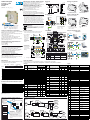
Modulo di I/O digitali
6 ingressi e 2 uscite
per guida DIN
linea D8
Quick Guide • 17/11 • ISTR_Q_D8_1_03_--
viale Indipendenza 56, 27029 - Vigevano (PV)
Tel.: +39 0381 698 71, Fax: +39 0381 698 730
internet site: www.ascontecnologic.com
E-mail: [email protected]
Dimensioni
Morsettiere
4 spine morsetti
Spina
alimentazione/
comunicazione
Tensione di alimentazione:
24Vac (-25...+12%) o
24Vdc (-15....+25%)
Presa
termi-
nazione
99 mm
3.9 in
22.5 mm
0.89 in
6.3 mm
0.25 in
114.5 mm
4.5 in
A
B
C
D
Rimozione dalla guida DIN
Togliere tensione allo strumento
12
Montaggio su guida DIN
1
CLICK
2
1 Agganciare la parte superiore
dello strumento sulla guida;
2 Ruotare lo strumento verso il
basso fino allo scatto;
1 Abbassare la slitta a molla
inserendo un cacciavite a lama
piatta come indicato;
2 Ruotare lo strumento verso
l’alto.
Dichiarazione di conformità e manuale istruzioni
Il D8 è uno strumento per montaggio retroquadro di Classe II
progettato per essere conforme alle Direttive europee.
Tutti i dettagli circa l’installazione e l’utilizzo dello strumento sono
inseriti nel manuale di installazione e nel manuale d’uso:
ISTR_I_D8_I_01_--.
pdf
e
ISTR_U_D8_I_02_--.pdf
.
I Manuali e la Dichiarazione di Conformità dello strumento
possono essere scaricati gratuitamente dal sito web:
www.ascontecnologic.com
Una volta collegato il sito internet indicato, cercare:
D8
poi selezionare D8 nell’elenco dei risultati.
Nella parte bassa della pagina dei prodotti (di qualsiasi lingua) è
presente l’area download con i collegamenti ai documenti relativi
al prodotto (nelle lingue disponibili).
Attenzione!
-
Qualora un guasto o un malfunzionamento dell'apparecchio possa
creare situazioni pericolose e/o dannose per persone, cose o
animali si ricorda che l'impianto deve essere predisposto con
dispositivi elettromeccanici aggiuntivi atti a garantire la sicurezza.
-
I prodotti sono coperti da una garanzia di 18 mesi dalla data di
spedizione. Dalla garanzia sono esclusi i prodotti e i componenti
soggetti ad usura per condizioni di utilizzo, vita utile e uso improprio.
Smaltimento
L’apparecchiatura (o il
prodotto) deve essere
oggetto di
raccolta separata in conformità alle vigenti normative
locali in materia di smaltimento.
Codice modello
La sigla del modello identifica le caratteristiche hardware del regola-
tore modificabili solo da personale qualificato.
Codice di configurazione
Un codice di 4 + 4 digit segue il codice modello (lettere I... R). Il codice
di configurazione serve per ordinare lo strumento preconfigurato.
[1] Solo per B = 2, 3, 4 e 5;
[2] Solo per B = 3, 4 e 5.
Linea D 8
Uscite DO1 - DO2 B
Relè - Relè 1
Relè - Logica 2
Logica - Logica 3
SSR - SSR 4
SSR - Logica 5
Funzioni speciali E
Non previste 0
2 Timer 2
Tipo di ingresso I
Nessun ingresso in frequenza 0
Ingresso in frequenza sul DI1 1
Ingresso in frequenza su DI1 e DI2 2
Tipo di uscita L
Nessuna uscita PWM 0
Uscita PWM su DO2 [1] 1
Uscita PWM su DO1 e DO2 [2] 2
Linea Base Accessori
Configurazione
1a parte
D8 5 B5 0-E90 0 /
Modello:
0 0 0 0
-
2a parte
IL0 0
Software di configurazione e impostazione
Lo strumento deve essere configurato mediante il software Controller
Explorer (programma proprietario gratuito).
La versione più recente del programma Controller Explorer può essere
scaricata dal sito internet:
www.ascontecnologic.com
Collegato il sito internet indicato selezionare: Download
poi cliccare sulla riga: Controller Explorer.
Effettuare il download della versione più recente del programma
più gli eventuali aggiornamenti.
Una volta installato il software e gli aggiornamenti, lanciare il
programma, i parametri di comunicazione di default sono:
Velocità di trasmissione: 9600 bps;
Protocollo: ModBus;
Indirizzo seriale: 247.
Attenzione!
Quando si devono installare più strumenti, porre attenzione al
fatto che l'indirizzo seriale di default è sempre = 247.
Per questa ragfione, alimentare o collegare sempre 1 strumento
per volta in modo da non avere attivi sulla stessa rete 2
strumenti con lo stesso indirizzo seriale.
Assegnare indirizzi diversi ad ogni strumento.
Il manuale "Configurazione e comunicazione seriale
gammadue® e deltadue®" può essere scaricato dal sito:
www.ascontecnologic.com
Come per gli altri manuali, anche quello indicato è presente nella
parte bassa della pagina specifica del prodotto.
Configurazione
e Supervisione
Morsetti
LL = 7 mm - 0.28 in. L = 7 mm - 0.28 in.
0.6 x 3.5 mm 0.4 x 2.5 mm
A - B - C - DCaratteristica Bus/Alimentazione
Filo
spelato
Cacciavite
a taglio
Coppia di
serraggio 0.5... 0.6 Nm 0.4... 0.5 Nm
Collegamenti
Interruttore
alimentazione
Presa con
resistenza
di termina-
zione linea
seriale (maschio) Spina bus alimentazione e
linea seriale (femmina)
NANPNTTL
DI6
NA
TTL
NPN
DI5
TTL
NPN
NA
RS485
24V
NC N
L
OP1 OP2
NPN TTL
NA
DI2
DI1
DI4
DI3
TTL NPN
NA
Hz
TTLNPN
NA Hz
Installazioni multiple
2 Dopo aver affiancato
tutti gli strumenti
inserire la spina
femmina a 5 poli
con resistenza di
terminazione
della linea seriale
nel corrispondente
maschio;
3 Cablare il connettore
di alimentazione
sulla spina maschio a
5 poli ed inserirla
nella corrispondente
femmina;
1
Dopo aver montato gli strumenti sulla guida, affiancarli in modo che il
connettore trasversale si inserisca nel connettore corrispondente;
12
3
4
22.5 x N + 53 mm
protezione connettori
3
4 A montaggio ultimato inserire le protezioni connettori su ambo i lati.
50 mm
1.969 in
Esempi di collegamento seriale
Configurazione
D8
RS485 CD-ROM con tool
di configurazione
D8 - 31 strumenti max.
Acquisizione e comando centralizzato
RS485
D8 - 31 strumenti max. Pannello operatore
RS485
Controllo locale
Elenco dei parametri
Nella tabella che segue sono elencati i parametri del regolatore con il relativo indirizzo seriale ModBus.
Per ulteriori informazioni si consulti il manuale: “Configurazione e comunicazione seriale gammadue® e deltadue®”.
Analogici Digitali
Indirizzo
ModBus Nome parametro Valore
Default Modbus Utente
0Stato logico interno ingressi
(bit da 1 a 6) e uscite (bit 7 e 8)
1 Frequenza DI1 (Hz)
2 Frequenza DI2 (Hz)
3 Frequenza PWM 0 0
4 Duty Cycle uscita DO1 0 0
5 Duty Cycle uscita DO2 0 0
6 Duty Cycle uscita DO1 all’accensione 0 0
7 Duty Cycle uscita DO2 all’accensione 0 0
30 Filtro DI1 0 0
31 Filtro DI2 0 0
32 Filtro DI3 0 0
33 Filtro DI4 0 0
34 Filtro DI5 0 0
35 Filtro DI6 0 0
49 Tipo di timer - Timer 1 none 0
50 Ingresso digitale associato al Trigger
- Timer 1 none 0
51 Ingresso digitale associato al Reset
- Timer 1 none 0
52 Uscita digitale associata al Timer 1 none 0
53 Valore all’accensione
dell’abilitazione di Timer 1 00
54 Base dei tempi per il Periodo
(TP) - Timer 1 secondi 0
55 Base dei tempi il periodo
(TOn) - Timer 1 secondi 0
56 Valore impostazione periodo TP
- Timer 1 11
Indirizzo
ModBus Nome parametro Valore
Default Modbus Utente
57 Valore impostazione tempo di TOn
- Timer 1 11
58 Abilitazione Timer 1(TEn) 0 0
59 Reset Timer 1 0 0
60 Stato evento generato - Timer 1
61 Indicazione Stato timer - Timer 1
(0 = Stop; 1 = Run)
62 Trigger in memoria - Trimer 1 0
63 Tipo di timer - Timer 2 0 0
64 Ingresso digitale associato al Trigger
- Timer 2 00
65 Ingresso digitale associato al Reset
- Timer 2 00
66 Uscita digitale associata al Timer 2 0 0
67 Valore all’accensione
dell’abilitazione di Timer 2 00
68 Base dei tempi per il Periodo (TP)
- Timer 2 secondi
69 Base dei tempi il periodo TOn -
Timer 2 secondi
70 Valore impostazione periodo TP
- Timer 2 00
71 Valore impostazione tempo di TOn
- Timer 2 00
72 Abilitazione Timer 2 (TEn) 0 0
73 Reset Timer 2 0 0
74 Stato evento generato - Timer 2
75 Indicazione Stato timer - Timer 2
(0 = Stop; 1 = Run)
76 Trigger in memoria - Timer 2 0 0
Indirizzo
ModBus Nome parametro Valore
0 Stato logico interno - DI1
1 Stato logico interno - DI2
2 Stato logico interno - DI3
3 Stato logico interno - DI4
4 Stato logico interno - DI5
5 Stato logico interno - DI6
6 Stato logico interno - DO1
7 Stato logico interno - DO2
8 Stato logico TOGGLE - DI1
9 Stato logico TOGGLE - DI2
10 Stato logico TOGGLE - DI3
11 Stato logico TOGGLE - DI4
12 Stato logico TOGGLE - DI5
13 Stato logico TOGGLE - DI6
14 Stato logico FLIP-FLOP 1
15 Stato logico FLIP-FLOP 2
16 Stato logico FLIP-FLOP 3
17 Abilitazione HOLD uscita DO1 0 = libera;
1 = in HOLD
18 Abilitazione HOLD uscita DO2 0 = libera;
1 = in HOLD
19 Stato DO1 all’accensione 0 = uscita disabilitata;
1 = uscita abilitata
20 Stato DO2 all’accensione 0 = uscita disabilitata;
1 = uscita abilitata
22 Memorizzazione stato
32 Abilitazione NOT - DI1 0 = invariato;
1 = NOT ingresso
33 Abilitazione NOT - DI2 0 = invariato;
1 = NOT ingresso
34 Abilitazione NOT - DI3 0 = invariato;
1 = NOT ingresso
35 Abilitazione NOT - DI4 0 = invariato;
1 = NOT ingresso
36 Abilitazione NOT - DI5 0 = invariato;
1 = NOT ingresso
37 Abilitazione NOT - DI6 0 = invariato;
1 = NOT ingresso
38 Abilitazione NOT - DO1 0 = invariato;
1 = NOT uscita
39 Abilitazione NOT - DO2 0 = invariato;
1 = NOT uscita
43 Abilitazione Timer 1
44 Reset in memoria Timer 1 1 = esegue il reset
45 Evento (stato uscita) Timer 1
46 Trigger in memoria Timer 1
47 Abilitazione Timer 2 1 = esegue il reset
48 Reset in memoria Timer 2
49 Evento (stato uscita) Timer 2
50 Trigger in memoria Timer 2
Ingresso
dal campo
Dall’ingresso
di Reset
Ingresso
di Set
Abilitazione
NOT
Ingressi
NOT
Filtro
Stato logico
interno
TOGGLE
FLIP-FLOP
Uscita
verso il
campo
Stato logico
interno
Frequenza Duty
Cycle
LED
Stato uscita
all’accensione
Duty Cycle
all’accensione
Uscite
PWM
HOLD
Abilitazione
NOT
Abilitazione
HOLD
Abilitazione
PWM
LED
Schemi logico-funzionali
NOT
JP2 imposta gli
ingressi digitali
DI3, DI4, DI5, DI6
JP1 imposta gli
ingressi digitali
DI1, DI2
Ingressi liberi
da tensione
Impostazione
di default
Impostazioni valide
per JP1 e JP2
Ingressi
a contatto
Avvertenza!
Accertarsi che i jumper di configurazione degli
ingressi (JP1 e JP2) mettano in colle
gamento i
terminali 1 con 3 e 2 con 4 oppure
3 con 5 e 4
con 6 come indicato nei disegni.
Collegamenti differenti provocano l’intervento
della protezione impedendo l’accensione dello
strumento.
Jumper per la selezione del tipo di ingresso
-
 1
1
-
 2
2


in altre lingue
Documenti correlati
Altri documenti
-
ICP DAS USA I-8114W Manuale utente
-
RKC INSTRUMENT COM-ML-2 Manuale utente
-
-
-
-
-
-