
C6000-EN
Leggere attentamente il presente foglio istruzioni.
PASO S.p.A declina ogni responsabilità per danni a persone e/o
cose derivanti dalla non corretta installazione e dall’uso improprio
del prodotto. La messa in opera del diusore deve essere eettuata da
personale addestrato: un’errata installazione potrebbe comportare il
rischio di scossa elettrica.
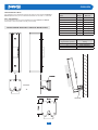
La serie C6000-EN è caratterizzata da un sistema di controllo della
direttività passivo integrato, che consente una dispersione verticale
costante in funzione della frequenza, con la possibilità di scegliere
tra due angoli: narrow e wide. Questa innovativa funzione garantisce
un’enorme essibilità d’impiego, che permette anche la congurazione
orizzontale delle colonne. Tutte le colonne alloggiano woofers full-range
da 3” (8 nei modelli C6120-EN e C6120N-EN, 4 nei modelli C6060-EN e
C6060N-EN). Tutti sono certicati IP55 per installazioni all’aperto, grazie al
cabinet completamente impermeabile con griglia rivestita di tessuto idrofobico,
altoparlanti con trattamento “waterproof” e copertura ermetica dei morsetti di
collegamento tramite coperchio dedicato. Queste colonne sono certicate per
l’utilizzo in sistemi d’emergenza ed evacuazione, sono dotate di morsettiera
ceramica e fusibile termico; sono dotate di trasformatore di linea 100 V con
livelli di potenza commutabili. La struttura è in alluminio estruso ed una vasta
gamma di accessori consente totale essibilità di congurazione del sistema.
CARATTERISTICHE FUNZIONALI
C6120-EN, C6120N-EN
• Line array a colonna passivo.
• 8 woofer custom full-range da 3” con bobina da 0,7”.
• Selettore angolo di dispersione verticale:
110°H x 15°V (narrow), 110°H x 40°V (wide).
• Connettore d’ingresso ceramico a vite con fusibile termico.
• Trasformatore di linea 100 V / 100 W con selettore di potenza.
• Cabinet in alluminio estruso verniciato a polvere.
• Griglia di protezione rivestita con tessuto idrofobico.
C6060-EN, C6060N-EN
• Line array a colonna passivo.
• 4 woofer custom full-range da 3” con bobina da 0,7”.
• Selettore angolo di dispersione verticale:
110°H x 25°V (narrow), 110°H x 50°V (wide).
• Connettore d’ingresso ceramico a vite con fusibile termico.
• Trasformatore di linea 100 V / 50 W con selettore di potenza.
• Cabinet in alluminio estruso verniciato a polvere.
• Griglia di protezione rivestita con tessuto idrofobico.
Please read this instruction sheet carefully.
PASO S.p.A. will accept no liability for personal injury and/or damage
to property resulting from incorrect installation or improper use of the
product. The speaker unit must be set up by trained personnel. Incorrect
installation could result in the risk of electric shocks.
C6000-EN range is characterized by an integrated passive directivity control
system which delivers a consistent frequency-based vertical dispersion, and
which oers users the choice of two angles - narrow and wide.
This functionality guarantees enormous exibility for the integrator, even
allowing for the horizontal mounting of columns. All the columns are equipped
with 3” fu
ll range woofers (8 for C6120-EN and C6120N-EN models, 4 for
C6060-EN and C6060N-EN). Suited to both indoor and outdoor use, IP55
certied, all models have the same sleek, lightweight and durable, powder-
coated aluminum housing. Completely dustproof and waterproof, the
enclosure’s grille is covered with a special hydrophobic fabric to ensure
absolute rejection of all atmospheric agents. The certied columns can be
used for emergency and evacuation applications. Other features include a
100V line transformer with switchable power levels. The structure is made of
extruded aluminum and a wide range of accessories is also available for total
system conguration exibility.
FUNCTIONAL FEATURES
C6120-EN, C6120N-EN
• Passive column array.
• 8 x 3” fullrange custom woofers with 0.7” voice-coil.
• Vertical dispersion angle selector:
110°H x 15°V (narrow), 110°H x 40°V (wide).
• Ceramic screw-in connector with thermal fuse.
• 100V / 100W line transformer with power selector.
• Extruded aluminum cabinet with powder coating.
• Grille with hydrophobic fabric.
C6060-EN, C6060N-EN
• Passive column array.
• 4 x 3” fullrange custom woofers with 0.7” voice-coil.
• Vertical dispersion angle selector:
110°H x 25°V (narrow), 110°H x 50°V (wide).
• Ceramic screw-in connector with thermal fuse.
• 100V / 50W line transformer with power selector.
• Extruded aluminum cabinet with powder coating.
• Grille with hydrophobic fabric.
I UK
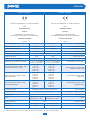
Colonne sonore 100 W / 50 W
100 W / 50 W Sound columns
Models
• C6060-EN
• C6120-EN
• C6060N-EN
• C6120N-EN
Safety: Compliant to EN 50200
Emergency: EN 54-24, EN 60849
Application: Outdoor environments (Type B)
Protection Degree: IP55
EN54-24 CERTIFICATE:
Nr. 0068/CPR/149-2020
EN54
16
EN54
24
EN54
16
EN54
24

C6000-EN
2
PER LA SOSPENSIONE DELLE COLONNE SERIE C6000-EN
UTILIZZARE ESCLUSIVAMENTE I SUPPORTI DI FISSAGGIO
PASO. L’UTILIZZO DI ALTRI SUPPORTI DI FISSAGGIO PUÒ
CAUSARE UNA PERICOLOSA INSTABILITÀ CON POSSIBILI
DANNI A PERSONE E COSE.
PASO S.p.A non è responsabile di eventuali danni a persone
o cose in caso di mancato rispetto delle presenti indicazioni
o mancata verica del fattore di sicurezza di tutti gli elementi
coinvolti nella sospensione del diusore.
TH
E C6000-EN SPEAKERS USE ONLY WITH PASO MOUNT
FOR WALL INSTALLATION. USE WITH OTHER MOUNTS
IS CAPABLE OF RESULTING IN INSTABILITY CAUSING
POSSIBLE INJURY.
PASO S.p.A. accepts no responsibility for any damage to people
or objects if these instructions are not complied with or if the
safety factor of all elements related to system suspension are
not properly checked.
INSTALLAZIONE
L’installazione delle colonne sonore serie C6000-EN,
impiegando gli accessori di sospensione descritti nel presente
manuale e le speciche istruzioni di montaggio, dovrà essere
eseguita esclusivamente da personale qualicato nel pieno
rispetto delle regole e degli standard di sicurezza in vigore nel
paese in cui avviene l’installazione.
• Gli accessori di sospensione sono costruiti per l’uso esclusivo
con le colonne serie C6000-EN e non sono stati progettati per
l’uso in combinazione ad alcun altro diusore o dispositivo.
• Ogni elemento del sotto, pavimento o altro supporto in cui
venga installata o appesa una colonna serie C6000-EN, deve
essere in grado di supportare il carico in piena sicurezza.
• Gli accessori di sospensione utilizzati devono essere agganciati
e ssati in sicurezza sia al diuosre che al sotto o altro
supporto. Quando si montano componenti su sotti, pavimenti
o travi, assicurarsi sempre che tutti i sistemidi aggancio e di
ssaggio siano di dimensioni e di capacità di carico appropriate.
• Tutti i diusori appesi in teatri, palasport o altri luoghi di lavoro
e/o intrattenimento, oltre al sistema di sospensione principale,
devono essere provvisti di sistema di sicurezza secondario
indipendente e di capacità di carico adeguata; a questo scopo,
possono essere utilizzati esclusivamente cavi di acciaio e catene
di costruzione e capacità di carico certicata.
IMPORTANTE
• La linea diusori (uscita dell’amplicatore) può avere una tensione
sucientemente alta (es. 100V) da costituire pericolo per le persone; non
procedere mai alla installazione o al collegamento dei diusori quando la
linea è in tensione.
• Assicurarsi che tutte le connessioni siano corrette e che la tensione di
ingresso (in un sistema a tensione costante) oppure l’impedenza del
diusore siano compatibili con le caratteristiche di uscita dell’amplicatore.
• Accertarsi che la linea diusori non possa essere calpestata o schiacciata.
• Impedire che liquidi od oggetti entrino all’interno del prodotto; potrebbero
causare corto circuito.
• Utilizzare solamente dispositivi / accessori specicati dal produttore.
• Quando è prevista l’installazione sospesa utilizzate solamente gli appositi
punti di ancoraggio. Vericare inoltre l’idoneità del supporto (parete,
sotto, ecc.) e dei componenti utilizzati per il ssaggio (tasselli, viti, ecc.).
• Per evitare fenomeni induttivi che diano luogo a ronzii o disturbi, le linee
diusori non devono essere canalizzate insieme ai conduttori dell’energia
elettrica, a cavi microfonici, a linee di segnale a basso livello (amplicatori).
• Non eseguire personalmente sul prodotto interventi / modiche / riparazioni
ma contattare centri di assistenza autorizzati o personale altamente
qualicato.
• Non usare solventi, alcool, benzina, o altre sostanze volatili per la pulizia
delle parti esterne; usare un panno asciutto.
IMPORTANT
• Loudspeaker lines (amplier outputs) can have a suciently high voltage
(i.e. 100 V) to involve a risk of electrocution: never install or connect this
loudspeaker when the line is alive.
• Make sure all connections have been made correctly and the loudspeaker
input voltage (in a constant voltage system) or its impedance is suitable for
the amplier output.
• Protect loudspeaker lines from damage; make sure they are positioned in
a way that they cannot be stepped on or crushed by objects.
• Make sure that no objects or liquids can get into this product, as this may
cause a short circuit.
• Use only the optional devices / accessories specied by the manufacturer.
• Also check the suitability of the support surface to which the product is
anchored (wall, ceiling, structure, etc.), and the components used for
attachment (screws, screw anchors, etc.).
• T
o prevent inductive eects from causing hum, noise and a bad system
working, loudspeaker lines should not be laid together with other electric cables
(mains), microphone or line level signal cables connected to amplier inputs.
• Never attempt to carry out any operations, modications or repairs that are
not expressly described in this manual. Contact your authorized service
centre or qualied personnel.
• Do not use solvents, alcohol, benzene or other volatile substances for
cleaning the external parts of this product.
AVVERTENZE PER LA SICUREZZA SAFETY WARNINGS
INSTALLATION
C6000-EN sound speakers must be installed using the ying
accessories described in this manual and following the
special assembly instructions by qualied sta only, strictly
complaying with the current regulations and safety standards
in force in the country of installation.
• The ying accessories are manufactured for their exclusive use
with C6000-EN systems and have not been designed for being
used with any other speaker or device.
• Any possible elements of the ceiling, oor or further supports
where C6000-EN systems are to be installed shall be able to
safety bear the load.
• The ying accessories in use are to be coupled and secured
safety to both the sound speaker and the ceiling (or the other
support). When components are tted to ceilings, oors or
beams, always make sure that all couplers and xing elements
are properly sized and have an adequate load capacity.
• Besides the main suspension system, all ying speakers in
theatres, indoor stadiums or in several other work and/or leisure
facilities shall be provided with an additional independent safety
system with the adequate load capacity. Only steel cables and
chains with certied load capacity can be used as an additional
safety device.

C6000-EN
3
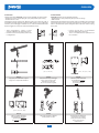
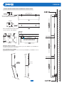
ACCESSORI
I diusori della serie C6000-EN possono essere installati nei seguenti modi:
• Sospensione in array tramite ying bar (con predisposizione per clamp);
• Posizionamento a muro.
Il ssaggio di tutti gli accessori al diusore avviene per mezzo di guide a
scorrimento integrate nella parte posteriore della colonna e perni di ssaggio
a molla. Il perno di ssaggio è realizzato con un sistema LOCK/UNLOCK che
assicura l’aggancio tra le parti in modo assolutamente sicuro.
ACCESSORIES
C6000-EN speakers can be installed as follows:
• Suspended in an array with ybar (with provision for clamp);
• Wall-mounted.
All the speaker accessories are secured by means of a sliding rail incorporated
into the back of the column, and xing pins with spring. The xing pin is made
witha a LOCK/UNLOCK system that guarantees a safe and correct coupling
of the parts.
AC6101 AC6102 AC6103
Flying bar per installazione sospesa
Flying bar for suspended installation
Giunto direzionale per il ssaggio
di due o più colonne tra loro
Directional joint for xing
two or more columns together
Attacco a parete direzionale
per installazione verticale
Directional wall mount
for vertical installation
AC6104 AC6105 AC6106
Attacco a parete direzionale
per installazione orizzontale
Directional wall mount
for horizontal installation
Clamp per aggancio su traliccio
Hooking clamp for trellis
Giunto sso per il ssaggio a
parete di due o più colonne
Fixed joint for wall mounting
two or more columns
between them
(0°, 5°, 10°, 15°, 20°)
(0°, 5°, 10°,15°)
• Tirare l’impugnatura e ruotare in senso
antiorario (UNLOCK) per sollevare il perno.
• Ruotare in senso orario (LOCK) per bloccare
il collegamento.
• Pull the grip and turn in a anti-clockwise
direction (UNLOCK) to lift the pin .
• Turn in a clockwise direction (LOCK) to lock
the connection.
(-10°, -5°, 0°, 5°, 10°)

C6000-EN
4
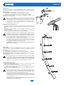
AC6105
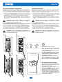
LINE ARRAY
Gli accessori di sospensione della serie C6000-EN sono stati progettati per garantire
un fattore di sicurezza di 5:1. Nella tabella (1) è riportato il peso netto dei diusori e
degli accessori.
L’esempio di congurazione riportato in gura è composto da:
n. 3 x C6120-EN, n. 1 ybar AC6101, n.1 clamp per aggancio AC6105,
n. 2 giunti direzionali AC6102 (peso totale 18,7 kg, comprensivo di accessori).
La tabella (2) indica la modalità di impostazione (NARROW o WIDE) in base
all’angolazione tra due diusori.
LINE ARRAY
The suspended accessories in the C6000-EN series have been designed to guarantee
a safety factor of 5:1. Table (1) illustrates the net weight of the speakers and of the
accessories.
The example conguration shown in the gure is composed of:
N.3 x C6120-EN, N. 1 ybar AC6101, N.1 hooking clamp AC6105, N. 2 adjustable
joints AC6102 (total weight 18.7 kg, inclusive of accessories).
Table (2) indicates the setting mode (NARROW or WIDE) based on the angle between
the two speakers.
AGGANCIO ALLA FLY BAR AC6101
• Posizionare e far scorrere la angia (A) nell’apposita sede nella part posteriore del
diusore no a quando il perno di ssaggio (B) non sarà scattato all’interno del foro
dedicato.
• Posizionare il “grillo di ssaggio” (C) in base all’angolo d’inclinazione che si vuole
assegnare al sistema.
• È possibile appendere il diusore su traliccio utilizzando l’accessorio AC6105 (da
utilizzare esclusivamente in combinazione con la ybar AC6101).
• Prima di ogni manovra assicurare sempre il completo serraggio del perno del grillo.
HOOKING THE FLYBAR AC6101
• Position and slide ange (A) in its housing at the back of the speaker until the xing
pin (B) clicks in inside its dedicated slot.
• Position the “xing shackle” (C) according to the desired angle of the system.
• The speaker can be hung on the lattice using the accessory AC6105 (to be used only
in combination with the AC6101 ybar).
• Before each manoeuvre, always check that the shackle pin is properly tightened.
N.B. Prima dell’installazione accertarsi che nella struttura portante del
sistema vengano inclusi nel calcolo del peso totale anche il peso degli
accessori, delle eventuali catene dei sollevatori, dei motori, dei cavi e ulteriori
pesi aggiuntivi. Nel caso in cui le suddette norme di sicurezza e il calcolo
del peso totale non siano rispettate, la PASO S.p.A. non è responsabile di
eventuali danni a persone e cose.
Controllare eventuali anomalie nel posizionamento. Eettuare un pre-
tensionamento di tutto il sistema e solamente dopo aver vericato la regolarità
di ogni elemento applicare la forza di movimentazione per sollevare il carico,
in maniera lenta, lineare e costante, evitando brusche accelerazioni o frenate,
che per inerzia possono innescare pericolose oscillazioni.
Durante l’intera manovra , l’operatore deve occupare una posizione tale da
consentirgli una via di fuga sicura in caso di incidente, cioè deve mantenersi
ad una adeguata distanza di sicurezza dal carico in movimento, mentre l’intera
area deve essere interdetta a chi non è autorizzato.
ATTENZIONE: un utilizzo errato o improprio può causare gravi danni a
persone e cose circostanti.
Check for any faults in the positioning. Pre-tension the entire system and only
after checking the regularity of each element, apply the necessary force to
slowly lift the load, in a linear and constant manner, avoiding sudden jolts or
braking, which due to inertia may cause dangerous swaying.
During the entire manoeuvre, the operator must be in a position allowing them
to safely escape in the event of an accident, that is, they must keep a safe
distance from the moving load, and the entire area must be cordoned o to
unauthorised persons.
CAUTION: incorrect or improper use may cause serious injury to persons
and damage to surrounding property.
N.B. During installation make sure that the calculation of the overall weights
for the system’s load-bearing structure includes the weight of the ybar, hoist
chains, motors, cables and other additional weights. Should the above safety
regulations and calculation of the overall weight not to be complied with,
PASO S.p.A. will not be liable for any damage to persons or property.
AC6105
AC6101

C6000-EN
5
PREDISPOSIZIONE A MURO
Per il ssaggio a muro del diusore utilizzare gli attacchi a parete direzionali AC6103 e
AC6104 rispettivamente per una installazione del diusore in verticale o in orizzontale.
WALL ARRANGEMENT
To x the speaker to the wall, use the adjustable wall hooks AC6103 and AC6104
respectively to install the speaker vertically or horizontally.
INSTALLAZIONE VERTICALE / VERTICAL INSTALLATION
AC6103
AC6103
Modello
Model
Peso
Weight
Massimo carico
Max load
C6060-EN, C6060N-EN 3 kg ------
C6120-EN, C6120N-EN 5,5 kg ------
AC6101 0,5 kg
20 kg
AC6102 0,6 kg ------
AC6103 0,8 kg 13 kg
AC6104 0,7 kg 3 kg
AC6105 0,5 kg 21 kg
AC6106 0,4 kg ------
Angolo tra i diusori
Angle between speakers
Impostazione
Setting
0° NARROW
5° WIDE / NARROW
10° ÷ 15° WIDE
Table (1)
Table (2)

C6000-EN
6
AC6106
AC6106
AC6106
AGGANCIO TRA PIÙ COLONNE
Per l’aggancio di due o più colonne tra loro utilizzare il giunto sso AC6106 o il giunto AC6105 se si
vuol dare una angolazione tra i due diusori.
HOOK BETWEEN TWO COLUMNS
To hook two or more columns to each other, use the xed joint AC6106 or joint AC6105 to create an
angle between the two speakers.
NEL LATO SINISTRO DEL DIFFUSORE
TO LEFT SIDE OF THE SPEAKER
NEL LATO SINISTRO DEL DIFFUSORE
TO LEFT SIDE OF THE SPEAKER
INSTALLAZIONE ORIZZONTALE/ HORIZONTAL INSTALLATION
SOLO UN DIFFUSORE C6060-EN
ONLY ONE SPEAKER C6060-EN
AC6104

C6000-EN
7
IMPORTANTI NOTE SUI CAVI
Per il collegamento delle colonne Serie
C6000-EN in un impianto d’evacuazione
vocale d’emergenza (EVAC) usare un cavo
omologato CEI 20-105.
Nel caso di installazione esterna del diu-
sore è NECESSARIO utilizzare un cavo con
diametro esterno 6-9mm per garantire l’im-
permeabilità del sistema.
ATTENZIONE: serrare bene il pressacavo.
Per un eventuale LINK, usare un pressacavo
PG9 in materiale con grado di auto-
estinguenza 94V0 e grado di protezione IP68.
IMPORTANT NOTES ON CABLES
To connect the speakers C6000-EN in an
EVAC emergency evacuation system, use a
CEI 20-105 approved cable.
To install the speaker outdoors, it is
STRICTLY NECESSARY to use a cable
with overall diameter 6-9mm in order to
guarantee the system’s impermeability.
CAUTION: tighten the cable gland properly).
To make a LINK, use a PG9 cable gland in a
material with self-extinguishing rating 94V0
and protection rating IP68.
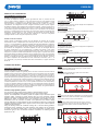
IMPOSTAZIONI PANNELLO POSTERIORE
I collegamenti con la linea audio si realizzano tramite il morsetto ceramico
presente all’interno della scatola di protezione (E). I due serraggi a vite
“+” e “–” permettono il collegamento sia del cavo d’ingresso sia di quello
d’uscita per la connessione in parallelo di altri diusori acustici (vedi gura).
• Per le linee a tensione costante a 100 V, posizionare il selettore sul
valore desiderato della potenza (25 W o 50 W per i mod. C6060-EN,
C6060N-EN - 50 W o 100 W per i mod. C6120-EN, C6120N-EN).
• Per il collegamento a bassa impedenza, posizionare il selettore su
16 Ω per i mod. C6060-EN, C6060N-EN e su 8 Ω per i mod. C6120-EN,
C6120N-EN.
REAR PANEL SETTINGS
Connections with the audio line are made using the ceramic clamp
included in the protective casing (E). The two screw clamps “+” and “–”
allow the connection of both the input cable and output cable for the
parallel connection of other speakers see gure).
• For 100V constant voltage lines, position the selector on the desired
power value (25W or 50W for the C6060-EN, C6060N-EN models)
(50W or 100W for the C6120-EN, C6120N-EN models).
• For the low impedance connection, position the selector on 16 Ω for
C6060-EN, C6060N-EN model sand on 8 Ω for C6120-EN, C6120N-EN
models.
CAVO D’INGRESSO
INPUT CABLE
CAVO D’USCITA
OUTPUT CABLE
ATTENZIONE: NON porre il selettore nella posizione di
impedenza costante quando il diusore è collegato in
modalità a tensione costante (100 V).
CAUTION: DO NOT position the selector on constant
impedance when the speaker is connected in constant
voltage mode (100V).
Il selettore NARROW / WIDE ore la possibilità di scegliere due angolazioni
diverse permettendo anche il montaggio orizzontale delle colonne:
110°H x 15°V (narrow), 110°H x 40°V (wide) per C6120-EN, C6120N-EN.
110°H x 25°V (narrow), 110°H x 50°V (wide) per C6060-EN, C6060N-EN.
Per l’installazione di più diusori a 0° utilizzare la modalità NARROW.
Per l’installazione del diusore in orizzontale utilizzare la modalità WIDE.
ATTENZIONE: Dopo aver eettuato i collegamenti e le
regolazioni è ASSOLUTAMENTE NECESSARIO riposizionare
la scatola di protezione (E).
The NARROW / WIDE selector oers the possibility to choose from two
dierent angles and also allows the columns to be horizontally mounted:
• 110°H x 15°V (narrow), 110°H x 40°V (wide) for C6120-EN, C6120N-EN.
• 110°H x 25°V (narrow), 110°H x 50°V (wide) for C6060-EN, C6060N-EN.
To install multiple speakers at 0° use the NARROW mode.
To install the speaker horizontally, WIDE mode is recommended.
CAUTION: After making the connections and necessary
adjustments, it is STRICTLY NECESSARY to reposition the
protective casing (E).

C6000-EN
8
Collegamento in serie
Le impedenze si sommano.
I quattro diusori da 4 Ω potranno essere collegati ad un amplicatore
che gestisce connessioni da 16 Ω.
Series connection
The impedances are added up.
The 4 x 4 Ω speakers can be connected to an amplier that manages
16 Ω connections..
Collegamento in parallelo
Le impedenze si dividono.
I quattro diusori da 16 Ω potranno essere collegati ad un amplicatore
che gestisce connessioni da 4 Ω.
PRIMA
All’impianto erano collegati cinque diusori per un totale di 55 W.
L’amplicatore scelto era da 60 W.
BEFORE
5 speakers were connected to the system for a total of 55W.
The selected amplier was 60W.
AFTER
Speakers were added and removed from the system. The total
requested power is now 87W. In this case it is sucient to change
the amplier, but the system (in terms of cables) will remain
unaltered.
DOPO
All’impianto sono stati aggiunti e tolti diusori. Ora la potenza totale
richiesta è di 87 W: in questo caso basterà cambiare l’amplicatore,
ma l’impianto (a livello di cavi) rimarrà inalterato.
Parallel connection
The impedances are divided.
The 4 x 16 Ω speakers can be connected to an amplier that manages
4 Ω connections.
MODALITÀ DI CONNESSIONE
COLLEGAMENTO DEI DIFFUSORI
Sistemi ad impedenza costante
Le uscite ad impedenza costante vengono generalmente usate in presenza di linee
con un numero ridotto di diusori di una certa potenza posti ad una distanza minima
dall’amplicatore. Il collegamento tra i diusori sarà un misto serie/parallelo, in modo
tale da ricondurre l’impedenza complessiva degli altoparlanti ad un valore non critico per
l’amplicatore; nel collegamento in serie, collegare il terminale positiov a quello negativo
del diusore seguente. Nel collegamento ad impedenza costante, è sempre meglio fare in
modo che la potenza totale dei diusori sia superiore a quella fornita dall’amplicatore; se
si necessita di regolare indipendentemente il volume di uno o più diusori o di escluderne
qualcuno, è indispensabile usare attenuatori che mantengano costante l’impedenza degli
altoparlanti: nel collegamento in serie, qualunque sia l’impedenza dei singoli diusori,
l’impedenza totale è data dalla somma delle impedenze; è comunque consigliabile
impiegare diusori acustici di uguale impedenza e potenza.
Sistemi a tensione costante
Q
uesto sistema di collegamento prevede che ogni diusore sia corredato da un proprio
trasformatore di linea. L’amplicatore deve essere provvisto di uscite a tensione costante
a 100 V / 70 V. Gli altoparlanti, collegati in parallelo all’uscita dell’amplicatore renderanno
semplice, se necessario, un ampliamento dell’impianto, derivandosi da uno qualsiasi dei
diusori installati in precedenza; allo stesso modo si possono eliminare gli altoparlanti non
più necessari. Nei collegamenti è necessario rispettare la “fase” sia del singolo diusore
al proprio trasformatore che nel collegamento in parallelo dei diusori. Sullo stesso
amplicatore si possono collegare contemporaneamente anche tutte le uscite a tensione,
sempre che la potenza nominale dell’amplicatore rimanga uguale o superiore alla somma
delle singole potenze dei diusori installati su di ogni singola linea in uscita. Con la semplice
formula: P = V
2
/ Z dove V è 100 V / 70 V e Z è l’impedenza primaria del trasformatore del
diusore, è possibile ill calcolo di qualsiasi potenza applicata ad ogni diusore; viceversa,
per sapere l’impedenza del trasformatore di linea conoscendo la tensione (100 V / 70
V) e la potenza (o le potenze) nominale dello stesso trasformatore, si applica la formula
Z = V
2
/ P.
CONNECTION MODES
SPEAKERS CONNECTION
Constant impedance speaker systems
Constant impedance outputs are generally used in the case of lines with a small number of
speakers having a certain power and being placed at a minimum distance from the amplier.
Speaker connection will be a combination of connection in parallel and series connection,
so to bring loudspeakers total impedance to a value which is not critical for the amplier. In
the series connection the positive lug shall be connected to the negative lug of the following
speaker. In the connection with constant impedance it is always recommended that speakers
total power is higher than the power supplied by the amplier.If in the connection with
constant impedance the volume of one or more speakers needed to be set independently
or also if any speaker needed to be switched o, the use of attenuators keeping impedance
constant is required. In the series connection, whatever the impedance of each speaker, the
total impedance results from the sum of all the impedances. Anyway, using sound speakers
with equal impedance and power is recommended.
Constant voltge speaker systems
This connection system implies that each speaker is equipped with its own line
transformer. The amplier shall be equipped with 100V / 70V constant voltage
outputs. The loudspeakers connected in parallel to amplier’s output will make system
expansion easier, if required, by simply shunting from any of the previously installed
speakers. Similarly, the loudspeakers which are not necessary anymore can be removed.
Matching the “phase” is necessary both in the connection of each speaker to its own
transformer and in the connection in parallel of the speakers.All the constant voltage
outputs (100V/70V) of a single amplier can be connected at the same time, provided that
amplier’s rated power remains equal or higher to the sum of the power of all the speakers
installed on each output line.
Using the following formula: P = V²/Z with V being 100 V / 70V and Z being speaker’s
transformer primary impedance any power applied to each speaker can be calculated.
If, instead, you know the voltage (100 V / 70 V) and the rated power (or powers) of the
transformer and you want to calculate transformer impedance, the following formula
applies: Z = V
2
/ P.

C6000-EN
9
La misurazione acustica utilizzata per le speciche elencate in questa tabella è realizzata in condizioni di campo libero
Acoustical measurement environment used for the specications listed in this table are made in free eld condition
C6060-EN, C6060N-EN C6120-EN, C6120N-EN
Potenza nominale 50 W 100 W Rated output
Trasformatore di linea (100 V) 50 W / 25 W 100 W / 50 W Line transformer (100 V)
Amplicatore raccomandato 100 W RMS 200 W RMS Recommended amplier
Impedenza nominale 16 Ω8 ΩRated impedance
Risposta in frequenza @ -6dB 150 ÷ 20.000 Hz Frequency response @ -6dB
Sensibilità @ 1W/1m 91 dB 94 dB Sensitivity @ 1W/1m
Pressione sonora SPL @ 1m/4m 106 dB / 94 dB 112 dB / 100 dB Maximum SPL @ 1m/4m
Selettore angolo di dispersione verticale H: 110° x V: 25° NARROW
H: 110° x V: 50° WIDE
H: 110° x V: 15° NARROW
H: 110° x V: 40° WIDE Vertical dispersion angle switch
Angolo di dispersione orizzontale (- 6dB)
Impostazione NARROW = WIDE
500 Hz: 360°
1 kHz: 170°
2 kHz: 125°
4 kHz: 125°
8 kHz: 100°
500 Hz: 360°
1 kHz: 170°
2 kHz: 125°
4 kHz: 125°
8 kHz: 100°
Horizontal dispersion angle (- 6dB)
NARROW = WIDE setting
Angolo di dispersione verticale (- 6dB)
Impostazione WIDE
500 Hz: 160°
1 kHz: 70°
2 kHz: 36°
4 kHz: 22°
8 kHz: 20°
500 Hz: 70°
1 kHz: 35°
2 kHz: 26°
4 kHz: 26°
8 kHz: 20°
Vertical dispersion angle (- 6dB)
WIDE setting
Angolo di dispersione verticale (- 6dB)
Impostazione NARROW
500 Hz: 160°
1 kHz: 70°
2 kHz: 28°
4 kHz: 14°
8 kHz: 9°
500 Hz: 70°
1 kHz: 35°
2 kHz: 18°
4 kHz: 10°
8 kHz: 10°
Vertical dispersion angle (- 6dB)
NARROW setting
Connettori d’ingresso Morsettiera ceramica / Ceramic terminal block Input connectors
Temperatura d’esercizio / Stoccaggio -25°C ÷ +55°C / -40°C ÷ +70°C Operating / Storage temperature
Umidità relativa < 95% Relative humidity
Colore C6060-EN: Bianco / White
C6060N-EN: Nero / Black
C6120-EN: Bianco / White
C6120N-EN: Nero / Black Colour
Grado di protezione IP 55 Protection degree
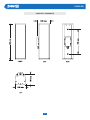
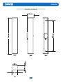
Dimensioni 100 x 368 x 125 mm 100 x 704 x 125 mm Size
Peso netto 3 kg 5,5 kg Net weight
20
PASO S.p.A Via Settembrini, 34 - 20020 Lainate (MI)
0068
0068/CPR/149-2020
EN 54-24
Loudspeaker for voice alarm systems
for re detection and re alarm systems for buildings
C6060-EN, C6060N-EN
Type B
20
PASO S.p.A Via Settembrini, 34 - 20020 Lainate (MI)
0068
0068/CPR/149-2020
EN 54-24
Loudspeaker for voice alarm systems
for re detection and re alarm systems for buildings
C6120-EN, C6120N-EN
Type B

C6000-EN
10
C6060-EN / C6060N-EN

C6000-EN
11
C6120-EN / C6120N-EN

S.p.A
Via Settembrini, 34 - 20020 Lainate (MI) - ITALIA
TEL. +39-02-580 77 1 (15 linee r.a.) - FAX +39-02-580 77 277
http://www.paso.it - UDT - 05/20 - 11/834
Nel continuo intento di migliorare i propri prodotti, la PASO S.p.A. si riserva il
diritto di apportare modiche ai disegni e alle caratteristiche tecniche in qualsiasi
momento e senza alcun preavviso.
PASO S.p.A. strive to improve their products continuously, and therefore reserve
the right to make changes to the drawings and technical specications at any
time and without notice.
Important information for correct disposal of the product in accordance with EC Directive 2002/96/EC This product must not be disposed of as urban
waste at the end of its working life. It must be taken to a special waste collection centre licensed by the local authorities or to a dealer providing this service.
Separate disposal of electric and/or electronic equipment (WEEE) will avoid possible negative consequences for the environment and for health resulting from
inappropriate disposal, and will enable the constituent materials to be recovered, with signicant savings in energy and resources. As a reminder of the need
to dispose of this equipment separately, the product is marked with a crossed-out wheeled dustbin.
Avvertenze per lo smaltimento del prodotto ai sensi della Direttiva Europea 2002/96/EC Alla ne della sua vita utile il prodotto non deve essere
smaltito insieme ai riuti urbani, ma deve essere consegnato presso gli appositi centri di raccolta dierenziata predisposti dalle amministrazioni
comunali, oppure presso i rivenditori che forniscono questo servizio. Smaltire separatamente un riuto elettrico e/o elettronico (RAEE) consente di
evitare possibili conseguenze negative per l’ambiente e per la salute derivanti da un suo smaltimento inadeguato e permette di recuperare i materiali
di cui è composto al ne di ottenere un importante risparmio di energia e di risorse. Su ciascun prodotto è riportato a questo scopo il marchio del
contenitore di spazzatura barrato.
Questo prodotto è conforme alle Direttive della Comunità Europea sotto le quali lo stesso ricade.
This product is in keeping with the relevant European Community Directives.
GARANZIA
Questo prodotto è garantito esente da difetti nelle sue materie prime e nel suo
montaggio; il periodo di garanzia è regolamentato dalle norme vigenti. La Paso
riparerà gratuitamente il prodotto difettoso qui garantito se il difetto risulterà
essersi vericato durante l’uso normale; la garanzia non si estende quindi
a prodotti usati ed installati in modo errato, danneggiati meccanicamente,
danneggiati da liquidi o da agenti atmosferici. Il prodotto, risultato difettoso,
dovrà essere inviato alla Paso franco di spese di spedizione e ritorno. Questa
garanzia non ne comprende altre, esplicite od implicite, e non comprende danni
o incidenti conseguenti a persone o cose. Contattare i distributori PASO della
zona per maggiori informazioni sulla garanzia.
Importante! L’utente ha la responsabilità di produrre una prova d’acquisto (fattura
o ricevuta) se vuole servirsi dell’assistenza coperta da garanzia. Dovrà inoltre
fornire data di acquisto, modello e numero di serie riportati sull’apparecchio; a
questo scopo, compilare come promemoria dei dati richiesti lo spazio qui sotto.
MODELLO: ...................................................................................................
NUMERO DI SERIE: ....................................................................................
DATA D’ACQUISTO: .....................................................................................
WARRANTY
This product is warranted to be free from defects in raw materials and assembly.
The warranty period is governed by the applicable provisions of law. Paso will repair
the product covered by this warranty free of charge if it is faulty, provided the defect
has occurred during normal use. The warranty does not cover products that are
improperly used or installed, mechanically damaged or damaged by liquids or the
weather. If the product is found to be faulty, it must be sent to Paso free of charges
for shipment and return. This warranty does not include any others, either explicit
or implicit, and does not cover consequential damage to property or personal injury.
For further information concerning the warranty contact your local PASO
distributor.
Important! Should the user wish to avail himself of servicing under the warranty,
he must provide evidence of the purchase (invoice or receipt). The user shall
also indicate the date of purchase, model and serial number indicated on the
equipment. For this reason, you should complete the box below as a reminder
of the data required.
MODEL: ........................................................................................................
SERIAL NUMBER: .......................................................................................
PURCHASE DATE: ......................................................................................
-
 1
1
-
 2
2
-
 3
3
-
 4
4
-
 5
5
-
 6
6
-
 7
7
-
 8
8
-
 9
9
-
 10
10
-
 11
11
-
 12
12


Paso C6120N-EN Manuale del proprietario
- Tipo
- Manuale del proprietario
in altre lingue
- English: Paso C6120N-EN Owner's manual
Documenti correlati
Altri documenti
-
 GLEMM BS 251 Manuale del proprietario
-
HELVIA GALA-606XW Guida utente
-
Shimano BR-C6000 Dealer's Manual
-
-
Focal OD STONE 8 Guida d'installazione
-
dBTechnologies DVA M2M+DVA M2S Manuale del proprietario
-
Shimano SM-DUE80 Manuale utente
-
-
-
 A.E.B. T12 Manuale utente

