nologo START-S5PV Manual For The Installer
- Tipo
- Manual For The Installer

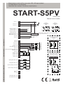
START-S5PV
• Single-phase control unit for one motor 230 / 400 opto-isolated
• For rapid doors or roll up doors
• Automatic time counter, 4 functions, bush function.
Manual for the installer
START-S5PV_230/400_281113_VXX17_GB www.ebtechnology.it www.nologo.info
Opening contactor
Closing contactor
Common contactor
Brake/Light COM
Brake/Light OLS NA
Brake/Light CLS NC
Lamp
Lamp
-11-
-10-
- 9 -
- 8 -
- 7 -
- 6 -
- 5 -
- 4 -
0 Vac
- 1 -
230 Vac
- 2 -
400 Vac
- 3 -
Test
Test
Common
Common
Common
Photo-beam close
Stop
Services (input for safety edge)
Pedestrian
Start
24 Vac
24 Vac
-19-
-18-
-17-
-16-
-15-
-14-
-13-
-12-
-22-
-21-
-20-
-24-
-23-
Common
-24-
Antenna
Opening limit-switch
-26-
Input for opening control
-28-
Input for closing control
-29-
Closing limit switch
-27-
BRAKE
Passive brake: In case of lack of tension the brake works
DIP 1 B - OFF (Par.no 4.4)
Output for lamp with
or without card
(DIP7)
4
6
5
6
4
5
6
Opening
remote-control
switch
Closing
remote-control
switch
TX RX
OUT24 Vac
Photocells working
in closing
N.C.
N.C.
N.O.
N.O.
N.O. N.O.
N.C.
24 Vac
Light
Light
-30-
-32-
-31-
Man present open
-33-
Man present close
With this connection the
“man present” is always
activated
This connection shows that
the “man present” is activated
with STOP function
32 33 34
N.O. N.O.
32 33 34
N.O. N.O.
16 17 18
230/400 Vac


Foreword
Thismanualprovidesallthespecicinformationyouneedtofa-
miliarize yourself with and correctly operate your unit.
Read it very carefully when you purchase the instrument and con-
sult it whenever you have doubts regarding use and before per-
forming any maintenance operations. The producer has the right
to modify the product without previous notice.
Environmental protection
measures
Information regarding the environment for customers
within the European Union. European Directive EC
2002/96 requires that units bearing this symbol on the
unit and/or on the packaging be disposed of separate-
ly from undifferentiated urban wastes.
The symbol indicates that the product must not be disposed of
with the normal household wastes. The owner is responsible for
disposing of this product and other electrical and electronic equip-
mentthroughspecicwastecollectionfacilitiesindicatedbythe
government or local public agencies. Correct disposal and recy-
cling help prevent any potentially negative impact on the environ-
ment and human
health. To receive more detailed information regarding disposal
of your unit, we recommend that you contact the competent pub-
lic agencies, the waste collection service or the shop where you
purchased the product.
1
Introduction
4
1.1
Safety precautions
1.2
Symbols and warning
1.3
Security system
1.4
Preliminary checks
1.5
Type of electrical wires
5
1.6
Type of installation
1.7
Connections Notes
2
Installation of the control unit
6
2.1
Description of the electrical connections
2.2
Scheme of the control board
7
2.3
Connection of the TENSION
8
2.4
Connection of the LAMP
2.5
Connection of a 24V light for working and opening gate
2.6
Connection of a CONTACTOR
2.7
Power supply to accessories
9
2.8
Connection of the PHOTO-BEAM
2.9
Connection of the PHOTO-BEAM with PHOTO-TEST
2.10
Connection of STOP devices
10
2.11
Connection of the OPENING
and CLOSING limit switches
2.12
Connection of the control OPENING “START”
and “PARTIAL OPENING”
2.13
Check of the connections
3
Functions and adjustment
11
3.1
Set up of the START control
and PARTIAL OPENING of the DIP A
3.2
COMPASS function of DIPA
3.3
Resume of the functions with other DIP A micro-switches
12
3.4
Set up of the DIP B
4
Installation of the plug-in receiver and managing
of the REMOTE CONTROL
13
4.1
Installation of the hybride
4.2
Cancellation of the MEMORY CODE
4.3
MEMORIZATION of a single remote control
5
Turn on and program of the control unit
14
5.1
Working time memorization
5.2
Memorization of the working time
with the OPENING CONTROL “START”
5.3
Working time memorization
with PARTIAL OPENING control
15
5.4
Increase the PAUSE TIME
6
Note
16
7
Declaration of CE conformity
17
Index
START-S5PV Technical manual
-3-
Self-learning working time
4 functions (collective use included)
Set up with dip-switch
Isolated contact for light of opening gated
Radiodecodesuppliedonlyforxedstandardcodesfrom
12 to 64 bit and HCS rolling code.
Reduced dimensions
Partial opening with separate control
Connection of the photo-beams with TEST
Description of the product
Small legend
LSO or FCA Open limit switch
LSC or FCC Close limit switch
START control to drive the gate
PEDESTRIAN in sliding units: control partial opening
Vac alternate current
Vdc direct current
NC normally closed
NO normally open
Isolated contact isolated from power supply

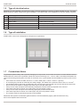
Making the correct choice of installation is essential to ensuring adequate safety and good protection against atmospheric
agents. Remember that the control unit contains powered parts and electronic components which by their very nature are
sensitivetoinltrationsandmoisture.ThecontrolunitissuppliedinacontainerwhichguaranteesanIP55protectionrating
ifadequatelyinstalled.Installthecontrolunitonapermanentsurfacethatisperfectlyat,adequatelyprotectedagainst
impacts and at least 40 cm off the ground.
The cables must enter the control unit from the bottom only; we recommend using wire leads and water-tight connections.
Whenusingtubingthatcouldllupwithwaterorifthetubingcomesfromanundergroundwell,thewiresmustentera
rstshuntingboxplacedatthesameheightasthecontrolunitandthen,fromthere,thewiresmustbepassedintothe
container holding the control unit, again entering from the bottom. This prevents any evaporation of the water in the tubing
from forming condensation inside the control unit itself.
1.4 Preliminary checks
1 Introduction
START-S5PV Technical manual
-4-
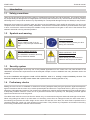
DANGEROUS
This is a warning and if it is not
respec it can provoque material dam-
age
DEVICE UNDER TENSION
The installation should be done only
from professional installer
Usingtheunitimproperlyandperformingrepairsormodicationspersonallywillvoidthewarranty.Theproducerdeclines
any responsibility for damages due to inappropriate use of the product and due to any use other than the use the product
wasdesignedfor.Theproducerdeclinesanyresponsibilityforconsequentialdamagesexceptcivilliabilityfortheproducts.
Rememberthatsystemsforautomaticgatesanddoorsmustbeinstalledbyhighlyqualiedtechniciansonlyandinfull
compliance with current law. Before starting installation, check that the mechanical consistency and sturdiness of the gate
or door, check that the mechanical stops are suitable to stop the movement of the gate or door even if the electrical limit
switches should fail or during manual operations.
1.1 Safety precautions
HEALTH DAMAGES
For safety reasons, protect your face
during the connection
READ CAREFULLY THE
OPERATING MANUAL
Read carefully this manul before in-
stallation and keep it for the future
1.2 Symbols and warning
1.3 Security system
These two simple diagrams show only one of the possible applications for this control unit. The risks inherent to the
“MACHINE” and the user’s requirements must be analyzed in depth in order to establish how many elements need to be
installed.
For a sure installation we suggest to install a STOP SWITCH, when it is working it stops immediatelly the door. The
SWITCH should have a normally closed contact and it opens when it is working (see Par. 3.10)

1.5 Type of electrical wires
Depending on the installation, the type and number of devices installed, the number of cables needed can vary. The table
below shows the cables needed for a typical installation. The cables used in the installation must be IEC 60335 compliant.
Power supply line Cable3x1,5mm
2
Motor cable (if not equipped) Cable4x1,5mm
2
Flashing signal Cable2x1,5mm
2
Antenna radio Shielded cable type RG58
Key selector Cable3x0,5o0,75mm
2
PhotoTx Cable4x0,5o0,75mm
2
PhotoRx Cable3x0,5o0,75mm
2
1.6 Type of installation
1.7 Connections Notes
To guarantee operator safety and to prevent damaging the components, never make connections or insert wireless receiver
boardswhilethecontrolunitispowered.Powerthecontrolunitthrougha3x1.5mm
2
cable. If the distance between the
controlunitandthegroundsystemconnectionismorethan30m,agroundplatemustbeinstalledinproximitytothecontrol
unit.
• Ifthemotorsdonothaveacable,usethe4x1.5mm
2
cable (open + close + common + ground).
• Inconnectingthepartwithanextremelylowsafetyvoltage,usecableswithaminimumsectionof0.5or0.75mm
2
.
• Useshieldedcablesifthelengthexceeds30mandconnectingthegroundbraidonlyfromthesideofthecontrolunit.
• Do not connect the cables in underground cases even if they are water-tight.
• If they are not used, the inputs to the Normally Closed (NC) contacts must be jumpered to the common”
• If the same input has more than one contact (NC), they are placed in series.
• If they are not used, the inputs to the Normally Open (NO) contacts are left loose.
• If the same input has more than one contact (NO), they are to be placed in series.
• The contacts must be mechanical and free of any potential.
Rememberthatsystemsforautomaticgatesanddoorsmustbeinstalledbyhighlyqualiedtechniciansonly
and in full compliance with current law.
START-S5PV control unit is designed for roll-up doors or rapid doors.
START-S5PV Technical manual
-5-

2.1 Description of the electrical connections
0 Vac 1 0 Vac
230 Vac 2 230 Vca 50 Hz power supply
400 Vac 3 400 Vca 50 Hz power supply
Opening contactor 4 Output for OPEN contactor
Closing contactor 5 Output for CLOSE contactor
Common contactor 6 Output for COMMON contactor
Common 7
Brake or a signal light (opening limit switch)
can be connected to the terminal board no.7-8-9.
Use DIP B according to the instructions of Par. No.4.4
N.O. 8
N.C. 9
Lamp
10
Outputforlightor230Vaccourtesylight,maximumpowerfor100Wlamp
11
Test
12
Isolated contact for PHOTO-TEST
13
24 Vac
14
Output 24 Vac
15
Common 16 Common contact for: services, safeties.
Photo-beam close 17 Input for photo-beam (the PHOTO will work only when closing)
Stop 18 Input for STOP
Safety Edge 19 Input for SAFETY EDGE
Pedestrian 20 Input for PARTIAL OPENING
Start 21 Input for START control
Common 22 Common contact for: services, safeties
Common 23 Common contact for: services, safeties
Common 24 Commoncontactfor:services,safeties,coaxialantennacable
Antenna 25 + Antenna
OLS 26 Input for OPENING limit switch
CLS 27 Input for CLOSING limit switch
Open 28 Input for OPEN
Close 29 Input for CLOSE
Isolated contact 30 Isolated contact for light
Isolated contact 31 Isolated contact for light
man present OPEN 32 Contact for “man present” OPEN
man present CLOSE 33 Contact for “man present” CLOSE
Common 34 Common
2 Installation of the control unit
START-S5PV Technical manual
-6-

START-S5PV Technical manual
-7-
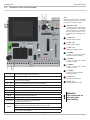
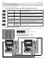
2.2 Scheme of the control board
Out +12 Vdc
Common
Out +24 Vdc
0 Vac
230 Vac
400 Vac
LED
When the control unit is powered,
the lights LED are turned on when
the common contact is closed.
9 - RED - ON
Opening limit switch (NC)
8 - RED - ON
Closing limit switch (NC)
7 - GREEN
it turns on when the OPEN
contact is closed.
6 - GREEN
it turns on when the CLOSE
contact is closed.
4 - GREEN
It turns on when the PEDE-
STRIAN contact is closing.
3 - RED - ON
SERVICES contact closed.
2 - RED - ON
STOP contact closed.
1 - RED - ON
PHOTO contact closed.
5 - GREEN
It turns on when the START
contact is closing.
LED TEST - RED
It indicates if the control uniti s
workingproperly.Itshouldash
each second and it indicates
that the micro-processor is ac-
tivated and it is waiting for con-
trols.
WARNING!
This control can be
used only with
limit-switches
1 2
230 Vac power supply of the control unit
1 3
400 Vac power supply of the control unit
4 11
230 Vac power supply of the motor,
230Vac contact for lamps
12 25
Tension for accessories, inputs services and safeties
26 27
Input for closing limit switch
28 29
Input for open and close control
30 31
Free contact for light
32 34
“Man present” function with open and close
DIP A Set up the function of the control unit
DIP B Set up the function of the control unit
Pulsante P
For radio code receiver, power adjustment,
increase of the pause time
Fuses
Fuse for Transformer power supply, Signal Light (term. board 10-11) and
fuse for remote-control switch (term. board 4-5-6): F1 - 4A
Fuse accessories and logic: F2 - 630mA
Fuse for brake: F2 - 630mA
F2 - 630 mA
F1 - 4A
F3 - 630 mA

START-S5PV Technical manual
-8-
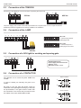
2.3 Connection of the TENSION
230 Vac
1 2 3
Connection of the TENSION. It can be two ways of powering the control unit:
The power supply of the control unit should be protected from a magnet-switch or from a couple of 5A fuses.
A differential switch is suggested if it is already available in the installation.
1 2 3
400 Vac
2.4 Connection of the LAMP
ON
CTS
2
1
43 6
5
87 10
9
ON
CTS
2
1
43 6
5
87 10
9
4 5 6 7 8 9 10 11
230 Vac
DIP 7 ON
In case the lamp without
ashinglightcard.
DIP 7 OFF
In case the lamp has a
ashinglightcontrolcard.
2.5 Connection of a 24V light for working and opening gate
12 13 14 15 16
30 31
Terminal board 14-15
Power supply of the accessories
Tension: 24Vac
Maximum current: 300mA
2.6 Connection of a CONTACTOR
4
6
5
6
Open Contactor
Close contactor
4 5 6
Pay attention not to invert the poles OPEN and
CLOSE.
In case of doubts put manually the gate in the
middle.
Be ready to stop the gate with STOP control.To
make sure of the opening and closing try to interrupt
the photo-beams, if the gate closes it means that
the connection is not correct and you need to invert
the cables of the motor OPEN AND CLOSE.

START-S5PV Technical manual
-9-
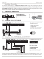
Description of securities
The control unit dispose of inputs for CLOSING PHOTO-BEAM and STOP.Therstcontactisactivatedonlywhenthe
motor is closing or is in pause time; if this safety intervene while the motor is closing, the control unit stops and invert the
motor until a new completely opening, while if the intervention is during the pause time it recharge the pause time and it
doesn’t recluse.
The input STOP is activated in any condition. If this input is not connected to the common input (terminal board 16-18) the
control unit won’t accept any control and it stops immediately the motor if it is moving.
2.8 Connection of the PHOTO-BEAM
12 13 14 15 16 17 18 19 20 21 22 23 24 25
POWER SUPPLY TO
RX PHOTOCELL
Photocell
receiver.
N.C. contact
POWER SUPPLY TO
TX PHOTOCELL
If the input
PHOTO is not
used, make a
link (16-17)
2.9 Connection of the PHOTO-BEAM with PHOTO-TEST
12 13 14 15 16 17 18 19 20 21 22 23 24 25
POWER SUPPLY TO
TX PHOTOCELL
POWER SUPPLY TO
RX PHOTOCELL
Photocell
receiver.
N.C. contact
ON
CTS
2
1
43 6
5
87 10
9
To activate the PHOTO-TEST put in
ON the micro-switch 6 of DIPA
The contact of the receiver of the
photo-beam should be:
- isolated from tensions
- normally closed
If you install more couple of photo-
beams make a serial connection.
The contact of the receiver of the
photo-beam should be:
- isolated from tensions
- normally closed
If you install more couple of photo-
beams make a serial connection.
Thephoto-testmakesurethattheautomationisworkingproperly.Thecontrolunitwillrstdoatestbeforeopening.Incase
the installation of photo-beam is not good, the control unit will turn on the lamp for 5 seconds and the gate won’t working.
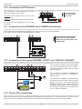
2.7 Power supply to accessories
Terminal Board 14-15
Power supply accessories
Tension: 24Vac
Maximum current: 300mA
12 13 14 15 16 17 18 19
Common
Out +24 Vdc
Out +12 Vdc

START-S5PV Technical manual
-10-
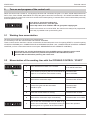
2.11 Connection of the OPENING and CLOSING limit switches
You can see both limit switches in the picture but in this control unit you can use separately.
The contact of the limit switches are NORMALLY CLOSED
12 13 14 15 16 17 12 13 14 15
OPEN CLOSE
If the inputs OLS (opening limit
switch) or OLS ( closing limit
switch) are not used, make a link.
(16-26) (16-27)
2.12 Connection of the control OPENING “START” and “PARTIAL OPENING”
12 13 14 15 16 17 18 19 20 21 22 23 24 25
The connection of openinc control with START
can be done with every button or N.A. contact.
If more devices are available, they should be
parallel connected.
The connection of PARTIAL OPENING can
be done with every button or a NORMALLY
OPEN contact.
You can connect a TIMER to plan the opening
and closing time of the gate, with the terminal
board no.16 and 21. The contact should be
NORMALLY OPEN and it should e closed for
all time the gates is open. If the connection of
the opening is available in the terminal board
no.21, connect it in parallel.
2.13 Check of the connections
Check the correct tension of the terminal board, the right lighting of the red N.C. l.e.d., watch the TEST l.e.d. which should
asheachsecond,thesafetyfunctionandthecorrectdirectionofthegate(therstmanoeuvrewillbeOPEN)
2.10 Connection of STOP devices
15 16 17 18 19 20
The connection of safety devices can be down
with every button or a NC contact.
BUTTON: it stops temporary the control unit until
a new function.
SWITCH: the automation stops until a new reset.
If more devices are available they can be serial
connected.
If the input STOP
is not used make a
link. (16-18)

START-S5PV Technical manual
-11-
The control unit dispose of DIP A which can used to activate different functions to make the installation suitable to the
customer’s requirements and for more safety.
3 Functions and adjustment
3.1 Set up of the START control and PARTIAL OPENING of the DIP A
1-OFF 2-OFF
Each control the motor invert.
If it is en pause it recloses.
1-ON 2-OFF
When opening it ignore the controls, when closing it inverts and re-
open, when pause it recharges the pause time.
1-OFF 2-ON
When opening and when closing the motor stops and they invert at
thenextcontrol.ITDOESN’TRECLOSEAUTOMATICALLY
1-ON 2-ON
When opening and when closing the motors stop and the invert at
thenextcontrol.ITRECLOSEAUTOMATICALLY
3-ON
Inhibits
the opening
control
It inhibits the opening control if the photo-beam has been obscured
when the door is closed
ON
2
1
43
5
ON
2
1
43
5
ON
2
1
43
5
ON
2
1
43
5
ON
2
1
43
5
ON
CTS
2
1
43 6
5
87 10
9
3.2 COMPASS function of DIPA
DIP4 can activate the “compass function“
DIP 4 ON
Activate the COMPASS function
The output TEST-PHOTO (12-13)
activate the opening of the another control unit.
Tthe outputs for LIGHT (30-31)
can be inhibited with the STOP control (16-18)
Control board 1
Control board 2
Central 1 Central 2
light 30 - 18 stop
light 31 - 16 common
photo test 12 - 16 common
photo test 13 - 28 open
common 16 - 31 light
stop 18 - 30 light
common 16 - 12 photo test
open 28 - 13 photo test

START-S5PV Technical manual
-12-
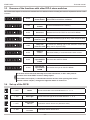
3.3 Resume of the functions with other DIP A micro-switches
The control board dispose of several micro-switches DIP A for different function according the customer requirements and for a safe
installation:
ON
CTS
2
1
43 6
5
87 10
9
ON
CTS
2
1
43 6
5
87 10
9
ON
CTS
2
1
43 6
5
87 10
9
ON
CTS
2
1
43 6
5
87 10
9
ON
CTS
2
1
43 6
5
87 10
9
ON
CTS
2
1
43 6
5
87 10
9
ON
CTS
2
1
43 6
5
87 10
9
ON
CTS
2
1
43 6
5
87 10
9
5-ON
Working time
memorization
Working time memorization
with START and PARTIAL OPENING.
5-OFF
Reset memoria
CODICI
It cancel all CODES in the memory.
6-ON Photo-test Activate the PHOTO-TEST for the PHOTO-BEAM.
7-ON
Lamp without
electronic card
Itactivatetheashinglightforlamp,230Voutputforlamp.
7-OFF
Lamp with
electronic card
It activate the ashing light of the electronic card of the
lamp, 230 V output for lamp.
8-ON
Delay in
referse
It activate a delay of 2 seconds before each reverse.
9-ON
Exclude the
input SAFETY
EDGE
ItexcludetheSAFETYEDGE
10-ON
Exclude the
input PHOTO
BEAM
ItexcludestheinputforPHOTO-BEAM
If the door will be removed manually at not with limit-switch, or with “man present“
function at the next START control it always opens.
The contact no.7-8 (N.O.) is closed when the door arrives at the opening limit switch
and the contact 7-9 (N.C.) changes the opposite status of contact 7-8.
3.4 Set up of the DIP B
ON
2
1
1 - OFF Brake Connect the brake to the terminal board no. 7 - 8 - 9
1 - ON OSL Light Connect the OSL light to the terminal board no. 7 - 8 - 9
1 - OFF
Search time
LS = 5s
Limit switch search time at 5 s (Standard value)
2 - ON
Search time
LS = 30s
Limit switch search time at 30 s
ON
2
1
ON
2
1
ON
2
1

START-S5PV Technical manual
-13-
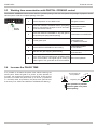
To manage the remote controls, the control unit should have a receiver. The control unit can manage different type of codes,
therstmemorizedcodewilldeterminethetypeofcode,consequentlyitcannotbememorizeddifferentcodesfromtherst.
The receiver will accept 12 to 64 bit codes.
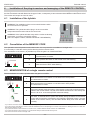
4 Installation of the plug-in receiver and managing of the REMOTE CONTROL
4.1 Installation of the hybride
WARNING! The installation of the receiver should be done when
the control unit is not powered.
WARNING! The hybride should be plug-in in the correct side:
componentsattheexteriorsideofthecontrolunit
WARNING! If the hybride will take away and the codes are already
memorized, you have to cancel the memory
(seenextchapterCODICI;CANCELLATIONOFTHEMEMORY)
4.2 Cancellation of the MEMORY CODE
This operation cancel all previous memorized codes. It is not prevue the cancellation of a single code.
Itisnecessarytoresetthememorybeforelearningtherstremotecontrol.
The cancellation of the memory is possible only when the gate is in closed POSITION.
ON
CTS
2
1
43 6
5
87 10
9
1
Make sure that the micro-switch no.5 of DIPA is in OFF position.
The automation is closed.
2 KeeppressedthebuttonPuntiltheledTESTstartashing
3 WaituntiltheledTESTstartsashing
15 seconds
4.3 MEMORIZATION of a single remote control
The memorization of a code is possible when the gate is CLOSED:
ON
CTS
2
1
43 6
5
87 10
9
1
Make sure that the micro-switch no.5 of DIAP are in OFF position.
The automation is closed.
2
Make sure that the micro-switch no.5 of DIP A are in OFF position.
The automation is closed.
3
Press and release slowly the button of the remote control which should be asso-
ciatedtothecontrolSTART.TheledTESTashes6timesand1timeslowlyand
then it is lit on for 10 seconds (START code memorized)
4
You have 10 seconds time to press and release slowly the button of the remote
control which should be associated to the PARTIAL OPENING control ( second
buttonoftheremotecontrol).TheledTESTashesfastly for 6 times and then
normally.
- If you need to memorize another remote control repeat the passage no.1
- If you don’t need to associate any control to PARTIAL OPENING, don’t do the passage no.4 wait for 8 seconds and 1 fl ashing for the l.e.d. TEST and
then the lamp fl ashes normally.
- If you press the remote control and the l.e.d. TEST is lit on, it means that the remote control is not COMPATIBLE
- If you press the remote control and the l.e.d. TEST fl ashes slowly it means that the memory is full.
- This control unit cannot cancel one single code
Component
side at the
exterior
side of the
control unit
START
PARTIAL
OPENING

START-S5PV Technical manual
-14-
Whenthecontrolunitisturnedon,ifeverythinghasbeenwellconnected,thegreel.e.d.TESTshouldashwhileSTOP,
FOTO, FCA, FCC e EDGE, SHOULD BE LIT ON (if the gate is close OLS is turned off). L.E.D START and PED have to be
turned off. When the control unit is turned on and the motor starts opening, it means that the control unit has been previously
turned off (tension cut off).
5 Turn on and program of the control unit
ON
CTS
2
1
43 6
5
87 10
9
If you have to set up the working time:
Turn off the control unit , close the gate
Put the dip-switch no.5 of DIPA in ON and give power supply again
Put the micro-switch no.5 in ON of DIPA, the control unit is ready to be programmed.
In this way is possible to set up the working time.
5.1 Working time memorization
Herewith the procedure for the working time memorization.
It is necessary to use the control START and PARTIAL OPENING.
These controls can be used from a device connected to the terminal boards 16-21 for opening START or 16-20 for opening
of PARTIAL OPENING (see “ CONNECTION OF AN OPENING CONTROL” and “ CONNECTION OF A PARTIAL OPENING
CONTROL) or from a memorized remote control (see “MEMORIZATION OF A REMOTE CONTROL”)
The operation can only be performed when in the CLOSED position. Starting from the initial
state of the electronic control unit, perform the operations described above, that is:
set switch DIP 5 to ON before powering the control unit.
5.2 Memorization of the working time with the OPENING CONTROL “START”
ON
CTS
2
1
43 6
5
87 10
9
1 Put in ON the micro-switch no. 5 of DIPA .
The automation is
in CLOSED POSITION
2
Press START (everything which is connected to the
input 21 or 1st channel of the remote control).
The automation
starts OPENING
3 Wait until the automation stops. The automation STOPS
4
Let the time goes until the automation
should be open.
The automation
“PAUSE TIME”
5 Press the control START for closing. The automation CLOSE
6 Wait until the automation stops automatically. The automation is CLOSED
7
Put in OFF the micro-switch no.5 of DIPA to go
back to the normal status. The lamps is turning on
and the green l.e.d. go back to the normal status.
End of the operation
ON
CTS
2
1
43 6
5
87 10
9
START

START-S5PV Technical manual
-15-
5.3 Working time memorization with PARTIAL OPENING control
The PARTIAL OPENING control can be used for a partial opening of the door and permit the passage of people or small
vehicles just to avoid the complete opening of the gate.
ON
CTS
2
1
43 6
5
87 10
9
1 Put the dip-switch no.5 of DIPA in ON The gate is closed
2
Press the PARTIAL OPENING button (everything
which is connected to the input no.20 or 2nd chan-
nel of the remote control)
L’automazione parte
in APERTURA
3
Press the PARTIAL OPENING to stop the gate in
the special point (stop partial opening)
L’automazione si ARRESTA
4 Let the gates open
L’automazione è
in “TEMPO DI PAUSA”
5 Press PARTIAL OPENING to start closing
L’automazione parte
in CHIUSURA
6 Wait that the gate stopping automatically
L’automazione è in posizio-
ne di CHIUSO
7
Put in OFF the micro-switch no.5 of DIPA to back
to the normal status. The signal light is turning off
and the green l.e.d. goes back to the normal status.
End of the operation
5.4 Increase the PAUSE TIME
It is possible to increase the pause time without learning the
working time. When the gate is on pause, by each pression of
Pbutton,the pause timeincreaseof 4 seconds.Thereareve
pression to increase the pause time up to 20 sec (5 pressions
x4 seconds).After sixpressions, the pausetime goesbackat
2seconds(l.e.d.STARTandPARTIALOPENINGareashing).
+ 4s
+ 4s
+ 4s
+ 4s
Time changing by
each pression
Beginning time
This operation is possible
when the gate is on pause
while opening.
PARTIAL
OPENING

START-S5PV Technical manual
-16-
6 Note

START-S5PV Technical manual
-17-
(according to EC Directive 98/37/EC, Attachment II, part B)
The undersigned,
Ernestino Bandera Administrator
DECLARES THAT:
Company: EB TECHNOLOGY SRL
Address: Corso Sempione 172/5
21052 Busto Arsizio VA Italy
Product’s name: START-S5PV
Single-phase control unit
7 Declaration of CE conformity
THE PRODUCT COMPLIES with what is outlined in the European Community directive:
98/37/CE
EC DIRECTIVE 98/37/CE ISSUED BY THE EUROPEAN PARLIAMENT AND
COUNCIL on june 22, 1998 harmonizing the legislation of the member countries
regarding machinery.
Reference: Attachment II, part B (EC Declaration of Conformity issued by the manufacturer).
THE PRODUCT COMPLIES with what is outlined in the European Community directives:
72/23/CE
EEC DIRECTIVE 72/23/CE ISSUED BY THE EUROPEAN COUNCIL on February
19, 1973 harmonizing the legislation of the member countries regarding electric
materials for use within certain voltage limits
Reference to harmonized standards: EN 60335-1
89/336/CE
EEC DIRECTIVE 89/336/CE ISSUED BY THE EUROPEAN COUNCIL on May 3,
1989, harmonizing the legislation of the member countries regarding
electromagnetic compatibility.
Reference to harmonized standards: EN 61000-6-2 EN 61000-6-3
IL PRODOTTO E’ CONFORME
with the essential requirements of article 3 of the following
European Community Directive, for the use for which the
product is designede
1999/5/CE
EC DIRECTIVE 1999/5 ISSUED BY THE EUROPEAN PARLIAMENT AND
COUNCIL on March 9, 1999 regarding wireless units and telecommunications
terminals and their reciprocal recognition
Reference to harmonized standards: ETSI EN 300 220-3 ETSI EN 301 489-1 ETSI EN 301 489-3
The directive 98/37/CE remind that it is not allowed the function of the product until the machine, for which the
product is included, is not indentify and declared conformed to the 2006/42/CE directive.
Dairago, li 31 march 2010
L’Amministratore
Ernestino Bandera

START-S5PV Technical manual
-18-
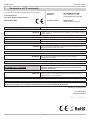
DICHIARAZIONE DI CONFORMITA’
Il sottoscritto, rappresentante il seguente cos-
truttore, dichiara che l’apparecchio denomi-
nato
START-S5PV
risulta conforme a tutte le norme tecniche
relative al prodotto entro il campo di applica-
bilità delle Direttive Comunitarie 73/23/CEE,
89/336/CEE e 99/5/CEE
Sono state eseguite tutte le necessarie prove
di radiofrequenza
EB TECHNOLOGY SRL
Corso Sempione 172/5
21052 Busto Arsizio (Va)
Italy
Questa dichiarazione viene emessa sotto la
sola responsabilità del costruttore e, se ap-
plicabile, del suo rappresentante autorizzato.
Busto Arsizio (Va) - Italia, 31/03/2010
ERNESTINO BANDERA
Amministratore
DECLARATION OF CONFORMITY
The undersigned, representative of the fol-
lowingmanifacturer,hereby certies that the
equipment known as
START-S5PV
complies with all technical requirements
concerning this product within the domain of
application of the EC Directives 73/23/CEE,
89/336/CEE and 99/5/CEE
All necessary radiofrequency tests have been
performed
EB TECHNOLOGY SRL
Corso Sempione 172/5
21052 Busto Arsizio (Va)
Italy
This declaration is rendered under the man-
ifactu-rer’s sole responsability, and if appli-
cable, under responsability of his authorized
representative.
Busto Arsizio (Va) - Italia, 31/03/2010
ERNESTINO BANDERA
Administrator
DÉCLARATION DE CONFORMITÉ
Le soussigné, représentant du constructeur
suivant certie que les appareils ci-dessus
référencés
START-S5PV
sont conformes à toutes les normes tech-
niques relativement au produit dans le do-
maine d’application des Directives Europée-
nnes 73/23/CEE, 89/336/CEE et 99/5/CEE
Toutes les essais de radiofréquence néces-
saires ont été effectués
EB TECHNOLOGY SRL
Corso Sempione 172/5
21052 Busto Arsizio (Va)
Italy
Cette déclaration est présentée sous la seule
responsabilié du constructeur et, si applica-
ble, de son représentant autorisé.
Busto Arsizio (Va) - Italia, 31/03/2010
ERNESTINO BANDERA
Administrateur
KONFORMITÄTSZERTIFIKAT
Der Unterzeichner bescheinigt, dass das
Produkt
START-S5PV
allen technischen Produktegesetzen, laut den
Europäische Gesetzen 73/23/CEE, 89/336/
CEE e 99/5/CEE, entspricht.
Alle Radiofrequenzprüfungen haben bei der
nachstehenden Firma stattgefunden:
EB TECHNOLOGY SRL
Corso Sempione 172/5
21052 Busto Arsizio (Va)
Italy
Diese Bescheinigung wird unter der alleinigen
Verantwortung des Herstellers ausgestellt
und dort woanwenbar, auch unter der des
befugten Vertreters.
Busto Arsizio (Va) - Italia, 31/03/2010
ERNESTINO BANDERA
Verwalter
DECLARACIÓN DE CONFORMIDAD
Elabajormante,representanteelfabricante
siguiente, declara que el equipo denominado
START-S5PV
es conforme con todas las normas técnicas
correspondientes al producto en el campo
de aplicación de las Directivas Comunitarias
73/23/CEE, 89/336/CEE y 99/5/CEE
Han sido realizadas todas las necesarias
pruebas de radiofrequencia.
EB TECHNOLOGY SRL
Corso Sempione 172/5
21052 Busto Arsizio (Va)
Italy
Estadeclaraciónseexpide bajolaexclusiva
responsabilidad del fabricante y, si de apli-
cación, de su representante autorizado.
Busto Arsizio (Va) - Italia, 31/03/2010
ERNESTINO BANDERA
Administrador
DECLARACÃO DE CONFORMIDADE
O abaixo-assinado, represendo o seguinte
construtor declara que o aparelho denomi-
nado
START-S5PV
é conforme a todas as normas técnicas relati-
vas ao produto dentro o campo de aplicabili-
dade das Diretivas Comunitarias 73/23/CEE,
89/336/CEE e 99/5/CEE
Foramexecutadastodasasnecessáriaspro-
vasderádiofrequência.
EB TECHNOLOGY SRL
Corso Sempione 172/5
21052 Busto Arsizio (Va)
Italy
Esta declaração verm emitida somente com a
responsabilidadedoconstrutore,seaplicáv-
el, do seu representante autorizado.
Busto Arsizio (Va) - Italia, 31/03/2010
ERNESTINO BANDERA
Administrador


EB TECHNOLOGY S.r.l.
Corso Sempione 172/5,
21052 Busto Arsizio VA Italia
tel. +39 0331.683310
fax.+390331.684423
posta@ebtechnology.it
www.ebtechnology.it
NOLOGO S.r.l.
via Cesare Cantù 26,
20020 Villa Cortese MI Italia
tel. +39 0331.430457
fax.+390331.432496
www.nologo.info
-
 1
1
-
 2
2
-
 3
3
-
 4
4
-
 5
5
-
 6
6
-
 7
7
-
 8
8
-
 9
9
-
 10
10
-
 11
11
-
 12
12
-
 13
13
-
 14
14
-
 15
15
-
 16
16
-
 17
17
-
 18
18
-
 19
19
-
 20
20


nologo START-S5PV Manual For The Installer
- Tipo
- Manual For The Installer
in altre lingue
- English: nologo START-S5PV
Altri documenti
-
Key Gates CT-400 Manuale utente
-
SEA Gate 1 DG R2BF Manuale del proprietario
-
SEA Gate 1 DG R1 Manuale del proprietario
-
-
-
 quiko QK-FTPMINI Manuale utente
-
-
-
SEA Slide DG Manuale del proprietario
-
 GiBiDi SC230E Manuale del proprietario

