
R
Automatic Gate Openers
Rev. 03 - 03/2019cod. 67412090
Unigate FV
SEA S.p.A.
Zona industriale 64020 S.ATTO Teramo - (ITALY)
Tel. +39 0861 588341 r.a. Fax +39 0861 588344
www.seateam.com [email protected]
ENGLISH
FRANÇAIS
ESPAÑOL
ITALIANO
1

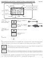
Control unit power supply: 230 Vac 50/60 Hz - 115Vac 50/60 Hz
Absorption in stand by: 30 mA
Environment temperature: -20°C +50°C
Specications of external box: 325,7 X 246 X 140
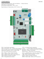
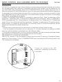
COMPONENTS
CN1 = Input/output connectors
CN2 = Limit switch, 24V~, Electric lock connector
CN3 = Encoder terminal board/PositionGate/gp1/gp2
Jolly/Cloud connector Jolly 3 or Sea Cloud
FIX = FIX receiver plug in connector
CR1 = Relay 1 clean contact terminal
CR2 = Relay 2 clean contact terminal
2PM = 2PM module power supply connector
CNB = Batterie charger connector
CNP = Programming connector
CLS = Limit switch quick connector
Power - + = Power supply switching connector
Module 1 = Motor 1FV module/2PM module connector
Module 2 = Motor 2 FV module
Master/Slave = Mater/Slave card connector
Progr = Programming connector through Open
Exp = SEM 2 external module connector
CNR = UNI receiver connector
Battery = Back up battery CR 2032
MEM = Radio trans. memo for FIX receivers
ENGLISH
2

MENU
SEA
SET
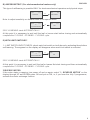
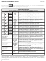
To reactivate an NC contact, follow this procedure:
Go to and press OK for 5 seconds, then enter the INPUT CHECK MENU and
check the operating status of all inputs
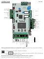
CONNECTIONS
No need to repeat self programming after reactivation of N.C. contacts.
The herein reported functions are available starting from revision 00.14
Warning: Automatic detection of not used N.C. inputs (Photocells, Stop, Limit switch and Edges)
ENGLISH
V 00.14 or
subsequent
COM (-)
1
CN1
2 3 4 5 6 7 8 9 10 11 12 13
CR1 CR2
CNF
2212029181716141 51
23
CN3
Master/Slave
Progr
54001590
UNIGATE DG
MEM
Display
Battery
Exp
Radio Module
Jolly/Cloud
FIXFIX
UP Down OK
24V
LSC1
LSC01
COM
Module1
Module2
Power 2 PM
Power Battery charger
COM
5V 24V
COM
COM1 NO1 NC1 COM2 NO2 NC2
-+ -S +
24 25 26 27 28 29 30
COM2 NO2 NC2
COM
COM1 NO1 NC1
24VDC
24VAC
FL -
+PG positive Position Gate
E1D1 Position gate data 1/
Encoder 1
E2D2 Position gate data 2/
Encoder 2
GP1 input
GP2 input
(+ encoder)
24V (1A max)
Closed limit switch
M2
Opened limit switch
M2
Comune
Closed limit switch
M1
Opened limit switch
M1
Electro lock
Clean contact
Clean contact
24V (1A max)
COMIS
(common accessories)
Antenna
Common
Start
Start Pedestrian
Stop
Common
Loop 1- Photocell 1
Loop 2- Photocell 2
Security edge 1
Security edge 2
Common
aux Programmabile
(24 VDC --- 1A max)
Flash Light
(500 mA max)
11

USB
USB
USB
USB
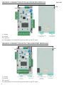
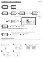
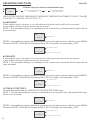
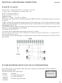
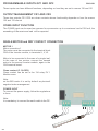
UNIGATE CONNECTION WITH AN INVERTER MODULE
It is mandatory to connect the ground cable to the PE input
It is mandatory to connect the ground cable to the PE input
L : phase
N: neutral
PE: ground
L : phase
N: neutral
PE: ground
UNIGATE CONNECTION WITH TWO INVERTER MODULES
ENGLISH
CN1
Inverter power supply
230 115 Vac
CN1
Inverter power supply
terminal
230 115 Vac
CN1
Inverter power supply
terminal
230 115 Vac
CN2
Dry contact and
motor output
CN2
Dry contact and
motor output
CN2
Dry contact and
motor output
4

INIT
MENU
MENU
MENU
MENU
MENU
MENU
SEA
SEA
SEA
SEA
SEA
SEA
SET
SET
SET
SET
SET
SET
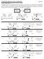
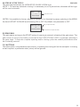
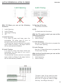
PARAMETER AND NO/NC CONTACTS PRE-CONFIGURATION
1)
2)
Power OFF
3)
Keep pressed the two buttons UP and DOWN and, at the same time, connect the power supply
cable for initialization of the control unit INIT appears on the display or go to menu 14: RESET
- When N.C.
(Photo, Stop, Limit
switch and Edge)
- When N.O.
(Start, pedestrian
start)
4)
All parameters return to default conguration, see column “Default” in the table of the
menus and all the inputs will show their real status
When the photocell
is crossed or input is
engaged
When input is not
engaged
When not engaged or
not wired
N.C. contacts
N.O. contacts
When input is engaged
.
.
5)
All NC contacts are automatically switched off if not used (no segments on display).
If the contacts are connected, they will be On on the display (segment switched on).
To reactivate the NC contacts it is necessary to enter each menu which shows the NC contacts
(e.g.: STOP, PHOTO, EDGE, LIMIT SWITCH....) and with SET put them on ON.
ENGLISH
Start
Photocell 1 Edge 1 Edge 2
Photocell 2
Pedestrian
opening
DISPLAY INPUTS STATUS
Stop
MENU
SEA
SET
- - -
- - - -
- - - -
Limit switch
opening motor 1
Limit switch
closing motor 1
Limit switch opening motor 2
(or slow opening BIG FAST)
Limit switch closing motor 2
(or slow closing BIG FAST)
5

QUICK START AND PROGRAMMING
Default (ON) = Single leaf
CHOOSE BETWEEN SINGLE OR DOUBLE LEAF
ATTENTION: This procedure is potentially dangerous and must only be performed by specialized
personnel
PRESET INSTALLATION
ENGLISH
1
2
3
3
A
B C
D E
MENU MENU
MENU
MENU
MENU
MENU
MENU
MENU
MENU
SEA SEA
SEA
SEA
SEA
SEA
SEA
SEA
SEA
LANGUAGE
English
START
Skip this step if you don’t want to programm a transmitter
Skip this step if you are working in sliding or single leaf mode
PRESS
BUTTON
STORED
Trasmitters
MOTOR
SINGLE
LEAF
RECEIVER
MISSING
UP
UP
UP
OK
OK
OK
OK
OK
OK
OK
Press the
button of
the TX to be
stored
Press
another
button or
another TX
to be store it
Choose the type
of motor with UP
or DOWN
With UP or DOWN choose
ON only if in single leaf mode
(motor 1)
Turn OFF the power
Put the power ON
Release the operators Manually push the leaves in half position
Reset the mechanical lock
If on the
display
appears
the item:
check if a
receiver
has been
connected
RX
Connector CNA
To conrm and
return to the
main menù
To conrm and
return to the
main menù
To exit
SET SET
SET
SET
SET
SET
SET
SET
SET
Remote control programming
After programming connect the antenna
Example
Example
Release
Release
6

M1
M1
M1
M1
M1
M1
M1
M1
M1
M1
M1
M2
M2
M2
M2
M2
M2
M2
M2
M2
M2
M2
P1
P1
P1
P1
M1 M2P1
M1 M2P1
2 MOTORS MANUAL SELFLEARNING
A) WITH IMPULSES *
The gate will start the following cycle: M2 CLOSING - M1 CLOSING - M1 OPENING - M2 OPENING
- M2 CLOSING - M1 CLOSING. To store the respective stops during cycle, press UP or DOWN or
START on each mechanical stop point of the leaf. Self-learning has been completed. In the case of
a single leaf the cycle will be CLOSING 1 - OPENING 1 - CLOSING 1.
ENGLISH
Press UP or TX, if stored, when
M2 is closed position.
M2 in closing
M2 in closing
M1 in closing
M1 in closing
M1 in opening
M2 in opening
M2 closed
M2 closed
M1 closed
M1 closed
M1 open
M2 open
Both doors halfway
Press UP or TX, if
stored, when M1 is
closed position.
Press UP or TX, if
stored, when M1 is in
closed position.
Press UP or TX, if
stored, when M2 is in
closed position.
Press UP or TX, if
stored, when M1 is
open position.
Press UP or TX, if
stored, when M2 is in
open position.
9
PROGRAMMING
OK
MENU MENU
SEA SEA
SET SET
OK
A
F
M
B
G
N
C
H
O
D
I
E
L
7

Make sure that, for all types of self-learning, the gate performs the following cycle: M2 CLOSING,
M1 CLOSING, M1 OPENING, M2 OPENING, M2 CLOSING, M1 CLOSING. Otherwise, see the
MOTOR REVERS function.
The cycle in case of single leaf will be CLOSE MOTOR 1 - OPEN MOTOR 1 - CLOSE MOTOR 1.
Note: to adjust sensitivity on obstacle refer to the special menu
SELF-LEARNING starts AUTOMATICALLY.
Now it is necessary to wait until the leaf or leaves rst start closing and then automatically complete
the CLOSING - OPENING - CLOSING cycle.
When an Encoder is installed, it is necessary to select ON in the 32-ENCODER menu
B) ENCODER *
When the potentiometer is installed, it is necessary to select
SELF-LEARNING starts AUTOMATICALLY
The potentiometer threshold intervention is set automatically during self-learning
IT IS NOT NECESSARY TO ADJUST THE MENU FROM
Note: to adjust sensitivity on obstacle refer to the special menu
ENGLISH
AUTOMATIC SELF-LEARNING 2 MOTORS
C) POTENTIOMETER *
MENU
MENU
MENU
MENU
MENU
MENU
MENU
MENU
MENU
MENU
MENU
MENU
SEA
SEA
SEA SEA
SEA
SEA
SEA
SEA
SEA
SEA
SEA
SEA
32 - encoder
32 - encoder
33
opening sensitivity
motor 1
38 pot.
from threshold
to opening 1
37
slowdown
sensitivity
45 pot. slowdown
threshold closing 2
9
programming
9
programming
ON
potentiomer
ON
ON
OK
OK
OK
OK
SET
SET
SET
SET
SET
SET
SET
SET
SET
SET
SET
SET
Now it is necessary to wait until the leaf or leaves start before closing and automatically complete
the cycle CLOSING - OPENING - CLOSING - OPENING with slowdown - CLOSING with slowdown
Note 2: With the potentiometer you can also make the self-learning giving impulses on favourite
opening or closing points; In this case it is also possible to modify the parameters I.AP.M1, I.CH. 1,
I.AP.M2, I.CH.M2 of + 100 impulses, if you need to optimize the initial and the nal position
Nota 3: In the case of MIXED PROCEDURE (AUTOMATIC stop detection in closing and with
MANUAL input in opening) the learning cycle will only be CLOSE-OPEN-CLOSE.
8

*REVERSE MOTOR
If the motor starts in opening, turn power off and on again, select “5 - REVERSE MOTOR” on the
display through UP and DOWN press OK and put on ON, or, if you have the Jolly 3 programmer,
activate the motor exchange function.
D) AMPEROMETRIC* (For electromechanical motors only)
This type of selearning is possible ONLY for electromechanical operators and physical stops.
Note: to adjust sensitivity on obstacle refer to the special menu
E) WITH LIMIT-SWITCHES*
1 - LIMIT SWITCH INPUT CHECK: check each limit switch on both doors by activating them before
self-learning. The segment on the display will disappear when each limit switch is activated
SELF-LEARNING starts AUTOMATICALLY
SELF-LEARNING starts AUTOMATICALLY
ENGLISH
MENU MENU
SEA
SEA
3 MOTOR MECHANIC
OK
SET
SET
MENU
MENU MENU
MENU
SEA
SEA SEA
SEA
9
PROGRAMMING
9
PROGRAMMING
ON
ON
OK
OK
SET
SET
SET
SET
At this point it is necessary to wait until the leaf or leaves start before closing and automatically
complete the CLOSING - OPENING - CLOSING cycle.
At this point it is necessary to wait until the leaf or leaves rst start closing and then automatically
complete the CLOSING - OPENING - CLOSING cycle.
9

OPERATING FUNCTIONS
ONLY AFTER THE SELF LEARNING OF WORKING TIMES WITH AUTOMATIC LOGIC, IT will BE
POSSIBLE TO CHANGE LOGICS INTO TO:
A) AUTOMATIC
A start impulse opens the gate. A second impluse during the opening will not be accepted.
A start impulse during closing reverses the movement.
NOTE 1: For automatic closing it is necessary to set a pause time, otherwise all the logics will be
semi-automatic.
NOTE2: It is possible to choose, whether to accept or not, the start in pause, selecting in the MENU
the item 8-START IN PAUSE and choosing ON or OFF. By default, the parameter is OFF.
B) SECURITY
A start impulse opens the gate. A second impulse during opening reverses the movement.
A start impulse during closing reverses the movement.
NOTE 1: For automatic closing it is necessary to set a pause time, otherwise all the logics will be
semi-automatic.
NOTE2: It is possible to choose, whether to accept or not, the start in pause, selecting in the MENU
the item 8-START IN PAUSE and choosing ON or OFF. By default, the parameter is OFF.
C) STEP BY STEP TYPE 1
The start impulse follows the OPEN-STOP-CLOSE-STOP-OPEN logic.
NOTE 1: To have the automatic closing it is necessary to set a pause time, otherwise all the logic
will be semi-automatic.
NOTE2: It is possible to choose, whether to accept or not, the start in pause, selecting in the MENU
the item 8-START IN PAUSE and choosing ON or OFF. By default, the parameter is OFF.
ENGLISH
MENU
SEA
7
Pause time
more than 0 sec
SET
MENU
SEA
7
Pause time
more than 0 sec
more than 0 sec
SET
MENU
MENU
MENU
MENU
SEA
SEA
SEA
SEA
7
Pause time
8
start in pause
8
start in pause
8
start in pause
ON (accepts the start)
ON (accepts the start)
ON (accepts the start)
OFF (doesn’t accepts the start)
OFF (doesn’t accepts the start)
OFF (doesn’t accepts the start)
SET
SET
SET
SET
6
MENU
SEA
Skip this step if you work in semi-automatic logic
Logic
OK OK
Choose the desired logic with
UP or DOWN
To conrm and return
to the main menu
SET
10

NOTE2: It is possible to choose, whether to accept or not, the start in pause, selecting in the MENU
the item 8-START IN PAUSE and choosing ON or OFF. By default, the parameter is OFF.
E) DEAD MAN
The gate opens as long as the START button of opening is pressed; releasing it the gate stops. The
gate closes as long as the button connected to the PEDESTRIAN START is pressed; releasing it
the gate stops. To execute complete opening and/or closing cycles the related pushbuttons must
be constantly pressed.
F) 2 BUTTONS
One start opens, one pedestrian start closes. In opening the closing will not be accepted. In closing
a start reopens, a pedestrian start (close) will be ignored.
D) STEP BY STEP TYPE 2
The start impulse follows the OPEN-STOP-CLOSE -OPEN logic.
NOTE 1: To have the automatic closing it is necessary to set a pause time, otherwise all the logic
will be semi-automatic.
ENGLISH
MENU
SEA
8
start in pause
ON (accepts the start)
OFF (doesn’t accepts the start)
SET
more than 0 sec
MENU
7
Pause time
SET
SEA
11

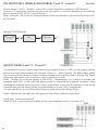
RADIO TRANSMITTER SELF LEARNING WITH
UNI RECEIVER ON BOARD OF CONTROL UNIT
WARNING: Make the radio transmitters programming before you connect the antenna and insert the receiver
into the special CMR connector (if available) with control unit turned off. With RF UNI and RF UNI PG module
it will be possible to use both Coccinella Roll Plus transmitters and radio transmitters with xed code. The rst
memorized radio transmitter will determine the type of the remaining radio transmitters. If the receiver is a
Rolling Code, press the button of the radio transmitter that you want to program twice to memorize the rst TX.
In the case of transmitters with xed code it is necessary to press 1 time the button of the transmitter you want
to program to store the rst remote control.
Notes:
- Perform the radio transmitters learning only with stopped cycle and closed gate.
- You can store max. 2 of the available 4 functions. If the control unit receives a code that has already been
assigned to another function it will be updated with the new function.
ENGLISH
RF UNI
RF UNI PG
old model
RF UNI PG
new model
16 users without memory
800 users with additional memory MEM
100 users xed code
800 users roll plus
100 users xed code
800 users roll plus
2
1
TX button
Memory location
4
serial
number
customer
1
0
2
3
3
MENU MENU MENU
MENU MENU
MENU MENU
MENU MENU
MENU MENU
MENU
MENU
MENU
MENU
MENU
MENU
MENU
MENU MENU
MENU
MENU
MENU
MENU
MENU
MENU
MENU
MENU
SEA SEA SEA
SEA SEA
SEA SEA
SEA SEA
SEA SEA
SEA
SEA
SEA
SEA
SEA
SEA
SEA
SEA SEA
SEA
SEA
SEA
SEA
SEA
SEA
SEA
SEA
SEA
SEA
START
press button
press button
press button
press button
press button
press button
press button
stored
stored
stored
stored
stored
stored
stored
0
OK
OK
ok? ok
Pedestrian
start
External
module
STOP
RELAY
Bistable
Stop
Delete a TX
Move on EEP
Clear memory
SET SET SET
SET SET
SET SET
SET
SET
SET SET
SET
SET
SET
SET
SET
SET
SET
SET SET
SET
SET
SET
SET
SET
SET
SET
SET
UP
UP
UP
UP
UP
UP
UP
UP
UP
OK
OK
OK
OK
OK
OK
OK
OK
OK
Conrm the cancellation
Press the
button of the
transmitter to
be stored
If you want to
program the
pedestrian start as
second channel
Press the
button of the
transmitter to
be stored
If you want to
program the
activation of the light
output as second
channel
Press the
button of the
transmitter to
be stored
If you want to
program the stop as
second channel
Press the
button of the
transmitter to
be stored
If you want to
program the second
channel to activate
relay CR1 or CR2
Press the
button of the
transmitter to
be stored
If you want to
program the stop as
bistale stop
Press the
button of the
transmitter to
be stored
Press the
button of the
transmitter to
be stored
If you want to delete
a single transmitter
Select with UP
and DOWN
the memory
location to be
selected and
press OK
Move the TX FIX’s
the extractable
memory (MEM)
If you want to delete
the whole memory
If you do not want to cancel , press UP or DOWN to
return to the 2 transmitters menu
Menu output
OK
OK
for 10 sec
for 10 sec
MENU
Release
END
SET
If you want to
program a button as
electric brake release
12

ATTENTION: Program the radio controls before connecting the antenna and inserting the receiver
into the appropriate CNS connector (if available) with the FIX RF module it will be possible to use
only xed code radio transmitter. Select the 2-TRANSMITTERS on the display and press OK, at
this point using the UP and DOWN buttons, select the command to associate the button (maximum
2 commands can be associated) and press OK to conrm the choice, now press the button of the
radio transmitter that you want to associate. If the memorization has been successful, the message
“Memorized” will appear on the display.
In MENU 2-TRANSMITTERS MENU it is possible to select the items: “Start” (to associate a Start
command), “Pedestrian Start” (to associate a Pedestrian Start command), “Stop” (To associate a
STOP command to the TX ), “Delete memory” (To delete all the TXs), “Delete one TX” (To delete the
single TX but if it is a Rolling Code Plus transmitter), “Release” (to associate the TX with the electric
brake release). To release the electric brake it is necessary to give 3 consecutive impulses, the 4th
impulse will reactivate the electric brake lock.
Note:
- Perform radio control learning only with control unit switched off and closed the gate.
- It will be possible to memorize up to a maximum of 16 codes (buttons), by adding the MEM
memory it will be possible to memorize up to 496 different codes.
- It is possible to memorize up to 2 of the 4 functions available. If a code is received that had already
been assigned to a function it will be updated with the new function.
DELETING THE TX FROM THE RECEIVER
With FIX RF modules, it will be possible to delete only the entire RX memory. Proceed as follows:
select the “Clear memory” in the 2-TRANSMITTERS menu and keep the OK button pressed until
“OK” appears on the display.
Connect the receiver to the CNS
connectors, respecting the direction
in the gure .
RADIO CONTROL SELF-LEARNING WITH FIX RECEIVER
ON BOARD
ENGLISH
13

Enter the menu and press the button OK for 5 seconds, you can enter the CHECK MENU,
where it is possible to check the operating status of all inputs.
Note: If the Stop, Photocell 1 and Photocell 2, Edge 1 and Enge 2 contacts are not bridged in
selearning, they will be deactivated and can be reactivated through this menu, without repeating
times selearning.
INPUTS CONTROL MENU
Language
MENU
SEA
SET
LIMIT SWITCH
CLOSING 1
LIMIT SWITCH
OPENING 1
EDGE
1
EDGE
2
PHOTO
1
PHOTO
2
END
LIMIT SWITCH
CLOSING 2
0.0 V
voltage level
on the
batteries
This item indicates the battery charge level
LIMIT SWITCH
OPENING 2
PARTIAL
OPENING
Enabled
Enabled
Enabled
Enabled
Enabled
Enabled
Enabled
Blocked
Blocked
Blocked
Blocked
Blocked
Blocked
Blocked
START
STOP
START
MENU
OK
OK
OK
OK
OK
OK
OK
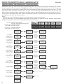
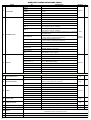
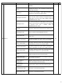
MENU FUNCTION TABLE
To access the Menu for input check keep pressed OK for about 5 seconds.
Description
Description
Exit menu
Start
Test
Stop
Test
Partial
Opening
Test
Safety
edge1
test
Safety
edge2
test
Photocell 1
test
Photocell 2
test
M1 Opening
limit switch
test
M1 Closing
limit switch
test
M2 Opening
limit switch
test
M2 Closing
limit switch
test
The contact must be a N.C. Contact. When activating the related
command on the display SET lights up, the input works. If SET is
always on, make sure that the contact is a N.C. contact or that the
related limit switch is not occupied.
The contact must be a N.C. Contact. When activating the related
command on the display SET lights up, the input works.
If SET is always on, make sure that the contact is a N.C. Contact
The contact must be a N.C. Contact. When activating the related
command on the display SET lights up, the input works.
If SET is always on, make sure that the contact is a N.C. Contact
The contact must be a N.C. Contact. When activating the related
command on the display SET lights up, the input works.
If SET is always on, make sure that the contact is a N.C. Contact
The contact must be a N.C. Contact. When activating the related
command on the display SET lights up, the input works. If SET is
always on, make sure that the contact is a N.C. Contact or that the
related limit switch is not occupied.
The contact must be a N.C. Contact. When activating the related
command on the display SET lights up, the input works.
If SET is always on, make sure that the contact is a N.C. Contact
The contact must be a N.C. Contact. When activating the related
command on the display SET lights up, the input works. If SET is
always on, make sure that the contact is a N.C. contact or that the
related limit switch is not occupied.
The contact must be a N.C. Contact. When activating the related
command on the display SET lights up, the input works. If SET is
always on, make sure that the contact is a N.C. Contact or that the
related limit switch is not occupied.
The contact must be a N.O. Contact . When activating the related
command on the display SET lights up, the input works.
If SET is always on, check the wirings.
The contact must be a N.C. Contact. When activating the related
command on the display SET lights up, the input works.
If SET is always on, make sure that the contact is a N.C. Contact
The contact must be a N.O. Contact. When activating the related
command on the display SET lights up, the input works.
If SET is always on, check the wirings.
ENGLISH
control
14

MENU
SEA
94 24V AUX
SET
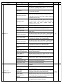
PHOTOCELL AND ANTENNA CONNECTIONS
A) 24V DC 11 and 12
PHOTOCELL 1 AND PHOTOCELL 2 (LOOP1 - LOOP2)
11 and 12 aux ~ (Accessories) 1A max COM = 0V
7 PH1 = Photocell contact 1
8 PH2 = Photocell contact 2
Default settings:
PHOTO 1 = “Close” - PHOTO 2 = “Open”
Photocell 2 can also be set as TIMER (see below TIMER function). For photocell options, see menu
97 and 98.
TIMER: holding PH2 pressed, the gate opens and remains open, while, when released, the gate
repeats the selected pause time and starts closing. If a safety device is activated, the Timer resets
automatically after 6 sec.
AUTOTEST function: make sure that the photocells are fully functional before any movement. If the
test fails, it will be indicated on the display.
To activate the AUTOTEST:
1) Connect the TX photocell power supply to the aux 12 inputs
2) Enter the 95-FOTOTEST menu and select on which accessory (Photocell 1 or Photocell 2 or
both) to activate this mode.
If you want to monitor the absorption of accessories, connect them to the inputs 20 of CN2 (COMIS)
max 350mA
B) CONFIGURATION 24V DC AUX CN1 12 CONFIGURATION
On the 24V AUX you can select when and how to operate the connected auxiliary accessory.
See menu 94-24V AUX.
The 94-24V AUX menu options are:
(See special menu)
• Always
• In cycle
• Opening
• Closing
• In pause
• Self-test
• In cycle and phototest
• In cycle and pause
• Indicator light gate open
ENGLISH
15

MENU
SEA
SET
10K PHOTOCELL (SINGLE OR DOUBLE) 7 and 11 - 8 and 11
On the clamps 7 and 11 - 8 and 11 of the CN1 it is also possible to connect a 10K Photocell.
On menu 121 type photo 1 and on the menu 122 type photo 2, it will work according to the settings
given from menu 97-PHOTO 1 and 98 Photo 2.
Note1: Using the 10K Photocell, further protection will be provided also in the event of a short-circuit
on the cables.
Setting 10 K Photocell
121 PHOTO 1
TYPE
SAFETY EDGE 9 and 11 - 10 and 11
It is possible to connect a safety edge between the contacts 9 and 11 of CN1 (or two edges, with the
second one connected between the contacts 10 and 11) . When pressed, the Safety Edge opens
the contact causing a partial inversion of the movement both in opening and in closing. The Safety
Edge input can be set «only in closing», «only in opening» or both.
Note1: Through the on-board display or the JOLLY 3 programmer it is possible to activate the
balanced edge 8K2, in this case the edge contact is controlled by a special resistance value
revealing the eventual involuntary short- circuit of the device. In the case of imbalance of the device
a special alarm will be shown on the on-board display or on the JOLLY programmer.
It is also possible to set two 8K2 Safety Edges on each single input Safety Edge.
Note2: Self-test can be made also on a powered radio Edge (See Auto-test Menu)
Latch open / latch close function
Inputs 10 and 11 can be set accordingly as latch open and latch close - see menu 118.
UP
OK
OK
MENU
MENU
SEA SEA
OFF Photo 10K
SET SET
ENGLISH
16

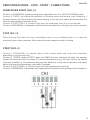
PEDESTRIAN START - STOP - START - CONNECTIONS
PEDESTRIAN START (N.O.) 4
Function 1 (STANDARD): partial opening space adjustable from 5 to 100 (90-OPENING menu)
Function 2 (TIMER): by holding the pedestrian (4) the gate opens and remains open. Releasing it
the gate repeats the selected pause and starts closing. In the case of a safety device activation the
timer will automatically reset after 6 sec.
Function 3 (2 BUTTONS): in 2 buttons logic press the pedestrian Start (4) to close the gate.
Function 4 (DEADMAN): in deadman logic this button executes the re-closing if you keep it pressed.
STOP (N.C.) 5
When pressing this button the motor immediately stops in any condition/position. To re-start the
movement give a start command. After a stop the motor always re-starts in closing.
START (N.O.) 3
Function 1 (STANDARD): an impulse given to this contact opens and closes the automation
depending on the selected logic.
Function 2 (TIMER): holding START starts the TIMER function, releasing the start, the operator
repeats the pause and then re closes. To connect other devices (e.g. the loop) refer to the related
instructions leaets (ie. loop detectors and proximity Switches). In the case of activation of a safety
device the timer will automatically reset after 6 seconds.
Function 3 (2 BUTTONS): in 2 buttons logic this button performs the opening.
Function 4 (DEADMAN): in deadman logic keep pressed the Start for the opening of the automation.
ENGLISH
17

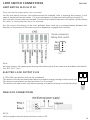
24V FLASHING LAMP 3W MAX 12 and 13
24V 3W Max Flashing Lamp (Control lamp)
The 24V Flashing Lamp is connected between the connectors 12 (24VDC AUX) and FLS (-) of CN
1.
The Flashing lamp advises that the automatic gate is moving with 1 ash/second in opening and
2 ashes / second in closing. During pause it remains switched on. Through the warning lamp it is
also possible to identify alarms lied to the STOP, PHOTOCELL 1, PHOTOCELL 2 and EDGE 1 and
EDGE 2 devices. Through the display or the JOLLY 3 programmer it is possible to activate the pre-
ashing function and/or to modify the function of the ashing lamp choosing between x ashing
or control lamp. The preashing can be timed from 0 to 5 seconds otherwise it is possible to set it
before closing only.
FLASHING LAMP- BUZZER
BUZZER (24V ) AUDIBLE ALARM
IMPORTANT NOTE: INSTEAD OF THE FLASHING LAMP, YOU CAN ALSO CONNECT A BUZZER
IN THIS CASE SET THE 86-MENU ON «BUZZER»
Use an autoswinging buzzer 24V of 100 dB. The buzzer will be activated after two consecutive
activations of the entrapment protection. To reset the alarm it is necessary to push the STOP button.
Anyway after 5 minutes the buzzer will stop to sound and the automation stands still waiting for
commands.
If Buzzer does not work, check if the 86-FLASHING LIGHT menu is set on “Buzzer”
ENGLISH
LED LAMP 3W
BUZZER
18

COM
LSO1
LSC1
24V
21 22
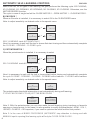
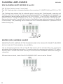
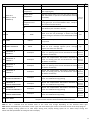
LIMIT SWITCH CONNECTIONS
LIMIT SWITCH 14 15 16 17 18
Does not need a jumper when not connected.
For the limit switch function, limit switches must be installed, both in opening and closing. In the
case of single-leaf connect motor 1 (it is not necessary to bridge the limit switches of motor 2).
Anti-intrusion function can be activated. This function needs at least one limit switch, which pushes
the motor in closing direction once it’s released.
ELECTRIC LOCK OUTPUT 21 22
A 12V=15W max electric lock can be connected
The electric lock can be deactivated when not used for energy saving on the control unit.
The electric lock release can be timed from 0 to 5 seconds
The electric lock can be set: only before opening, only before closing or in both directions.
MAGLOCK CONNECTIONS
NOTA:
set the negative electric brake function in menu 132.
For the correct functioning of the limit switches there must be a correspondence between the
direction of movement of the motors and the respective engaged limit switches.
Quick connector
sliding limit switch
CLS
Note:
on some motors, the opening and closing limit-switch inputs 2 are used as a slow-down limit switch.
See BIG FAST Joint.
ENGLISH
19

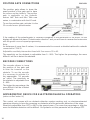
POSITION GATE CONNECTIONS
The position gate allows to know the
exact position of the gate and to have
the reverse on the obstacle. The position
gate is applicable on the hydraulic
motors Half Tank and Mini Tank new
series, in combination with the LE card.
Note:
for distances of more than 2 meters, it is recommended to connect a shielded cable with a sheath
connected to COM 25
If the reading of the potentiometer is reversed compared to the movement of the motor, on the
display will appear the alarm “Potentiometer direction” and you will have to reverse the brown wire
with the green one and repeat programming.
AMPEROMETRIC DEVICE FOR ELECTROMECHANICAL OPERATORS
(active on Surf motor IV)
This control unit comes with an obstacle detection system working only on electromechanical
operators allowing to have the reversing on obstacles and the automatic detection of the stops.
Sensitivity adjustable from OFF to 99% in the special menu. The more the percentage is high the
more the obstacle detection will be difcult. On hydraulic unit this parameter will be always OFF.
Adjustable sensitivity intervention threshold. See menus 33 to 45.
The sensitivity on the obstacle is adjustable from 0 - 99%. The higher the percentage, the more
difcult it will be to detect the obstacle.
ENCODER CONNECTIONS
The encoder allows to know
the position of the gate and
to have the inversion on the
obstacle. To use the encoder
it is necessary to activate it in
the appropriate “32 encoder
on” menu. The sensitivity on
the obstacle is adjustable from
0 - 99%.
The higher the percentage, the
more difcult it will be to detect
the obstacle
To use the position gate, activate it in the
32 encoder menu: potentiometer
ENGLISH
20
La pagina si sta caricando...
La pagina si sta caricando...
La pagina si sta caricando...
La pagina si sta caricando...
La pagina si sta caricando...
La pagina si sta caricando...
La pagina si sta caricando...
La pagina si sta caricando...
La pagina si sta caricando...
La pagina si sta caricando...
La pagina si sta caricando...
La pagina si sta caricando...
La pagina si sta caricando...
La pagina si sta caricando...
La pagina si sta caricando...
La pagina si sta caricando...
La pagina si sta caricando...
La pagina si sta caricando...
La pagina si sta caricando...
La pagina si sta caricando...
-
 1
1
-
 2
2
-
 3
3
-
 4
4
-
 5
5
-
 6
6
-
 7
7
-
 8
8
-
 9
9
-
 10
10
-
 11
11
-
 12
12
-
 13
13
-
 14
14
-
 15
15
-
 16
16
-
 17
17
-
 18
18
-
 19
19
-
 20
20
-
 21
21
-
 22
22
-
 23
23
-
 24
24
-
 25
25
-
 26
26
-
 27
27
-
 28
28
-
 29
29
-
 30
30
-
 31
31
-
 32
32
-
 33
33
-
 34
34
-
 35
35
-
 36
36
-
 37
37
-
 38
38
-
 39
39
-
 40
40


in altre lingue
- English: SEA Unigate FV User manual
Documenti correlati
-
SEA Gate 1 DG R1 Manuale del proprietario
-
SEA Gate 1 DG R2BF Manuale del proprietario
-
-
-
SEA Slide DG Manuale del proprietario
-
-
-
-
-
Altri documenti
-
 quiko QK-CE220RL4 Manuale utente
-
 quiko QK-CE220RL4 Manuale utente
-
 quiko QK-CE220RL4 Manuale utente
-
 quiko QK-CE220BATRL4 Manuale utente
-
 quiko QK-CE220BATRL4 Manuale utente
-
 quiko QK-CE220BATRL4 Manuale utente
-
 nologo START-S5PV Manual For The Installer
-
Omron VS MINI J7 Manuale del proprietario
-
Traceable 6440 Istruzioni per l'uso
-
Honeywell PS300 Manuale del proprietario


