Follett Horizon Elite HC Series Operation And Service Manual
- Categoria
- Fabbricatori di cubetti di ghiaccio
- Tipo
- Operation And Service Manual

HC_1810R/N, HC_2110R/N, HM_1810R/N, HM_2110R/N 1
HC_1810R/N, HC_2110R/N, HM_1810R/N, HM_2110R/N
Horizon Elite™ Ice Machines (Remote Condensing)
801 Church Lane • Easton, PA 18040, USA
Toll free (877) 612-5086 • +1 (610) 252-7301
www.follettice.com
Following installation, please forward this manual
to the appropriate operations person.
Operation and Service Manual
After Serial Number L60417
Order parts online
www.follettice.com
01157841R05

2 HC_1810R/N, HC_2110R/N, HM_1810R/N, HM_2110R/N

HC_1810R/N, HC_2110R/N, HM_1810R/N, HM_2110R/N 3
Contents
Welcome to Follett. . . . . . . . . . . . . . . . . . . . . . . . . . . . . . . . . . . . . . . . . . . . . . . . . . . . . . . . . . . . . . . . . . . . . . . . . . . . . . 4
Before you begin ............................................................................... 4
Specications .................................................................................5
Electrical ................................................................................... 5
Evaporator unit .............................................................................. 5
Condensing unit .............................................................................5
Evaporator plumbing .......................................................................... 5
Flush drain plumbing ......................................................................... 5
Ambient .................................................................................... 6
Refrigeration ................................................................................6
Weight .....................................................................................6
Ice production ...............................................................................6
Dimensions and clearances ....................................................................7
Operation .....................................................................................9
Cleaning/sanitizing and preventive maintenance (all models) ..........................................9
Service ...................................................................................... 13
Ice machine operation (all models) ............................................................. 13
Water system ................................................................................. 14
“Bin full” detection system ..................................................................... 15
Electrical system ............................................................................ 16
Mechanical System ............................................................................21
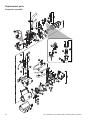
Evaporator disassembly ...................................................................... 21
Evaporator reassembly ....................................................................... 24
Refrigeration system ......................................................................... 29
Troubleshooting ..............................................................................32
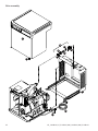
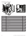
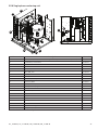
Replacement parts ............................................................................ 34
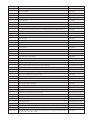
Evaporator assembly ........................................................................34
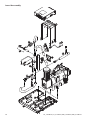
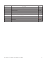
Low-side assembly ..........................................................................36
Electrical box ..............................................................................38
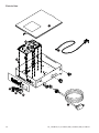
Integration kit – top-mount and RIDE remote ice delivery ........................................... 40
Skins assembly ............................................................................. 42
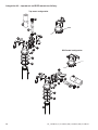
1810 Single-phase condensing unit ............................................................. 44
2110 Single-phase condensing unit .............................................................45
1810 3-phase condensing unit ................................................................. 46
2110 3-phase condensing unit ................................................................. 47

4 HC_1810R/N, HC_2110R/N, HM_1810R/N, HM_2110R/N
Welcome to Follett
Follett equipment enjoys a well-deserved reputation for excellent performance, long-term reliability and
outstanding after-the-sale support. To ensure that this equipment delivers the same degree of service, we ask
that you review the installation manual (provided as a separate document) before beginning to install the unit.
Our instructions are designed to help you achieve a trouble-free installation. Should you have any questions
or require technical help at any time, please call our technical service group at (877) 612-5086 or +1 (610) 252-
7301.
Before you begin
After uncrating and removing all packing material, inspect the equipment for concealed shipping damage. If
damage is found, notify the shipper immediately and contact Follett LLC so that we can help in the filing of a
claim, if necessary.
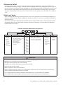
Check your paperwork to determine which model you have. Follett model numbers are designed to provide
information about the type and capacity of Follett equipment. Following is an explanation of the different
model numbers in the series.
ConfigurationApplication
S RIDE™
(RIDE remote
ice delivery
equipment)
T Top-mount
425 up to
425 lbs
(193 kg)
710 up to
675 lbs
(306 kg)
1010 up to
1061 lbs
(482 kg)
1410 up to
1466 lbs
(665 kg)
1810 up to
1790 lbs
(812 kg)
2110 up to
2039 lbs
(925 kg)
V Vision™
H Harmony™
B Ice storage bin
J Drop-in
M Ice Manager
diverter valve
system
P Cornelius Profile
PR150
CondenserSeriesVoltageIcemaker
C 208-230/60/1 (icemaking head)
Self-contained only.
D 115/60/1 (icemaking head)
Self-contained and remote. If remote
unit, high side is 208-230/60/1.
E 230/50/1 (icemaking head)
Self-contained only.
F 115/60/1 (icemaking head)
Remote only. High side is
208-230/60/3.
MC Maestro™
Chewblet
®
(425 Series)
HC Horizon
Chewblet
(710, 1010,
1410, 1810,
2110 Series)
HM Horizon
Micro Chewblet
HC 1810D SVA
A Air-cooled, self-contained
W Water-cooled, self-contained
R Air-cooled, remote condensing unit
N Air-cooled, no condensing unit for
connection to parallel rack system
Chewblet
®
Ice Machine Model Number Configurations
CAUTION
• Warranty does not cover exterior or outside installations.
• Moving parts. Do not operate with front cover removed.
• Hot parts. Do not operate with cover removed.
• To reduce risk of shock, disconnect power before servicing.
• Drain line must not be vented.
• Water supply must have particle filtration.
• Most ice machine cleaners contain citric or phosphoric acid, which can cause skin irritation. Read caution
label on product and follow instructions carefully.
• Ice is slippery. Maintain counters and floors around dispenser in a clean and ice-free condition.
• Ice is food. Follow recommended cleaning instructions to maintain cleanliness of delivered ice.

HC_1810R/N, HC_2110R/N, HM_1810R/N, HM_2110R/N 5
Specifications
Electrical
Separate, dedicated circuit and equipment ground required.
Evaporator unit
Standard electrical: 115/60/1
Maximum fuse: 15A
Amperage: 5A
Condensing unit
1810 Single-Phase 1810 3-Phase 2110 Single-Phase 2110 3-Phase
Electrical 208-230V, 60Hz
Max Circuit HVACR breaker size 45A 25A 45A 30A
Min Circuit Ampacity 26.2A 15.7A 27.1A 19.9A
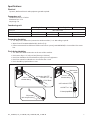
Evaporator plumbing
§ 3/8" OD push-in water inlet (connection inside machine) - 3/8" OD tubing required.
§ Water shut-off recommended within 10 feet (3 m).
§ Follett recommends installation of Follett water filter system (part# 00130286) in ice machine inlet water
line.
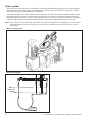
Flush drain plumbing
§ 3/4" MPT flush drain connection at the rear of the machine.
§ Drain must slope 1/4" inch per foot (6 mm per 30.4 cm).
§ Drain line should not be shared with any other piece of equipment.
§ Drain line cannot be reduced to a size smaller than 1 inch.
§ Drain should be piped without a vent.
3/4" barb x 3/4" FPT
1" Stand pipe/Drain
2 ft. x 1" OD
silicone tubing
Minimum 8"
radius
3/4" MPT x 1" slip
1" PVC Drain
2 ft. x 1" OD
silicone tubing
3/4" MPT x 1" slip
3/4" barb x 3/4" FPT
1'
1/4" per foot
(6,4 mm per 0,3 m)

6 HC_1810R/N, HC_2110R/N, HM_1810R/N, HM_2110R/N
Ambient
Evaporator unit
Air temperature 100 F/38 C max. 50 F/10 C min.
Water temperature 90 F/32 C max. 45 F/7 C min.
Water pressure 70 psi max. (483 kPa) 10 psi min. (69 kPa)
Condenser unit
Air temperature 120 F/49 C max. –20F/–29C min.
Refrigeration
§ 3/8" liquid line
§ 7/8" suction line
Note: Rack system installations require a capacity of 15,700 BTU/hr for 1810 machines and 18,200 BTU/hr for
2110 machines at 0 F (–18 C) evaporator temperature. Evaporator pressure regulator (not supplied) is
required.
Weight
Evaporator unit:
1810: 157 lbs (71.2 kg)
2110: 165 lbs (74.8 kg)
Condensing unit: 305 lbs (138.3 kg)
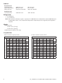
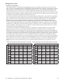
Ice production
1810 ice machine capacity/24 hrs.
Ambient Air Temperature F/C
Evap Potable Water Temperature F/C
F 60 70 80 90 100
C 16 21 27 32 38
50 1859 1784 1685 1616 1500 lbs
10 843 809 764 733 680 kg
60 1723 1684 1578 1563 1409 lbs
16 782 764 716 709 639 kg
70 1620 1594 1514 1420 1319 lbs
21 734 723 687 644 598 kg
80 1550 1487 1485 1351 1299 lbs
27 703 674 674 613 589 kg
90 1471 1435 1370 1285 1207 lbs
32 667 651 621 583 547 kg
2110 ice machine capacity/24 hrs.
Ambient Air Temperature F/C
Evap Potable Water Temperature F/C
F 60 70 80 90 100
C 16 21 27 32 38
50 2039 2039 1934 1825 1703 lbs
10 925 925 877 828 772 kg
60 1943 1888 1878 1710 1584 lbs
16 881 856 852 772 718 kg
70 1833 1781 1789 1634 1489 lbs
21 831 808 811 741 675 kg
80 1754 1686 1643 1535 1426 lbs
27 796 765 745 696 647 kg
90 1650 1603 1577 1457 1395 lbs
32 748 727 715 661 633 kg

HC_1810R/N, HC_2110R/N, HM_1810R/N, HM_2110R/N 7
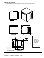
Dimensions and clearances
§ Entire front of ice machine must be clear of obstructions/connections to allow removal.
§ 1" (26mm) clearance above ice machine for service.
§ 1" (26mm) minimum clearance on sides.
A 22.5" (57.1 cm)
B 21.1" (53.6 cm)
C 22.9" (58.2 cm)
D 1. 8 " (4.5 cm)
E 20.8" (52.9 cm)
F 18.3" (46.4 cm)
G 2.7" (6.9 cm)
H 2.3" (15.3 cm)
I 5.0" (12.8 cm)
J 22.0" (55.9 cm)
K 22.7" (57.6 cm)
A
B
C
D
K
E
F
G
H
J
I
TOP VIEW
FRONT VIEW
BACK VIEW
3/8" LIQUID LINE
7/8" SUCTION LINE
3/8" OD PUSH-IN
WATER INLET
3/4" BARB DRAIN
NEMA 5-15
RIGHT ANGLE

8 HC_1810R/N, HC_2110R/N, HM_1810R/N, HM_2110R/N
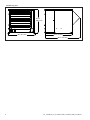
Condensing unit
30" (76.2 cm)
25.75"
(65.3 cm)
29.9" (76 cm)
38.5" (97.5 cm)

HC_1810R/N, HC_2110R/N, HM_1810R/N, HM_2110R/N 9
Operation
Cleaning/sanitizing and preventive maintenance (all models)
Note: Do not use bleach to sanitize or clean the icemaker.
Preventive maintenance
Periodic cleaning of Follett’s icemaker system is required to ensure peak performance and delivery of clean,
sanitary ice. The recommended cleaning procedures that follow should be performed at least as frequently as
recommended, and more often if environmental conditions dictate.
Cleaning of the condenser can usually be performed by facility personnel. Cleaning of the icemaker system,
in most cases, should be performed by your facility’s maintenance staff or a Follett authorized service agent.
Regardless of who performs the cleaning, it is the operator’s responsibility to see that this cleaning is performed
according to the schedule below. Service problems resulting from lack of preventive maintenance will not be
covered under the Follett warranty.
Weekly exterior care
The exterior may be cleaned with a stainless cleaner such as 3M Stainless Steel Cleaner & Polish or equivalent.
Monthly condenser cleaning (air-cooled icemaker only)
1. Use a vacuum cleaner or stiff brush to carefully clean condenser coils of air-cooled icemakers to ensure
optimal performance.
2. When reinstalling counter panels in front of remote icemakers, be sure that ventilation louvers line up
with
condenser air duct.
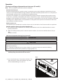
Semi-annual evaporator cleaning (every 6 months)
WARNING
• Wear rubber gloves and safety goggles (and/or face shield) when handling ice machine cleaner or sanitizer.
CAUTION
• Use only Follett approved SafeCLEAN Plus™ cleaning solution.
• DO NOT USE BLEACH.
• It is a violation of Federal law to use these solutions in a manner inconsistent with their labeling.
• Read and understand all labels printed on packaging before use.
Note: Complete procedure for cleaning an sanitizing MUST be followed. Ice must be collected for 10minutes
before putting ice machine back into service.
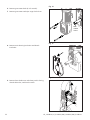
Fig. 1
1. Press the CLEAN button. The machine will drain. The
auger will run for a short time and then stop. Wait
for the LOW WATER light to come on.
LO WATER

10 HC_1810R/N, HC_2110R/N, HM_1810R/N, HM_2110R/N
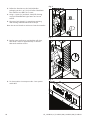
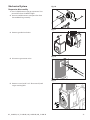
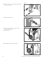
Fig. 2
2. Follow the directions on the SafeCLEAN Plus
packaging to mix 1 gal. (3.8 L) of Follett SafeCLEAN
Plus solution. Use 100 F (38 C) water.
3. Using a 1 quart (1L) container, slowly fill cleaning
cup until CLEANER FULL light comes on. Do not
overfill.
4. Place one Sani-Sponge™ in remaining sanitizing
and cleaning solution and retain for Step 9.
Note: Do not use bleach to sanitize or clean the icemaker.
CLEANER FULL
Fig. 3
5. Replace cover on cleaner cup. Machine will clean,
then flush 3 times in approximately 15 minutes.
Wait until machine restarts.
15
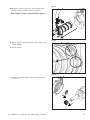
Fig. 4
6. To clean/sanitize ice transport tube – Press power
switch OFF

HC_1810R/N, HC_2110R/N, HM_1810R/N, HM_2110R/N 11
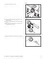
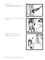
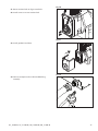
Fig. 5
7. Disconnect coupling as shown.
Fig. 6
8. Using disposable food service grade gloves, insert
dry Sani-Sponge.
9. Insert Sani-Sponge soaked in SafeClean Plus (from
Step 4).
10. Push both Sani-Sponges down ice transport tube
with supplied pusher tube.
1
2
3
16"
(407 mm)
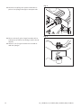
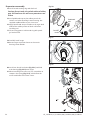
Fig. 7
11. Remove and discard 16 inch (407 mm) pusher tube.

12 HC_1810R/N, HC_2110R/N, HM_1810R/N, HM_2110R/N
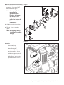
Fig. 8
12. Reconnect coupling. Press power switch ON. Ice
pushes Sani-Sponges through ice transport tube.
Fig. 9
13. Place a sanitary (2 gal. or larger) container in bin
or dispenser to collect Sani-Sponges and ice for 10
minutes.
14. Collect 5.5 lbs (3 kg) of ice from unit. Discard ice
and Sani-Sponges.

HC_1810R/N, HC_2110R/N, HM_1810R/N, HM_2110R/N 13
Service
Ice machine operation (all models)
Follett’s ice machine consists of five distinct functional systems covered in detail as follows:
§ Water system
§ Electrical control system
§ Mechanical assembly
§ Refrigeration system
§ Bin full
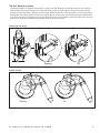
The Horizon ice machine overview
The Follett Horizon ice machine uses a horizontal, cylindrical evaporator to freeze water on its inner surface.
The refrigeration cycle is continuous; there is no batch cycle. The evaporator is flooded with water and the level
is controlled by sensors in a reservoir. A rotating auger (14 RPM) continuously scrapes ice from the inner wall
of the evaporator. The auger moves harvested ice through the evaporator into an ice extrusion canal. The ice
is forced through a restrictive nozzle that squeezes out the water and creates the Chewblet. The continuous
extrusion process pushes the Chewblets through a transport tube into a dispenser or bin.
A solid state PC board controls and monitors the functionality of the ice machine. In addition to sequencing
electrical components, the board monitors various operational parameters. A full complement of indicator
lights allows visual status of the machine's operation. Additionally, the PC board controls the self-flushing
feature of the ice machine. The evaporator water is periodically drained and replenished to remove minerals
and sediment.
A unique “bin full” detection system is incorporated in the Horizon ice machine. A switch located at the ice
discharge port of the machine detects the position of the transport tube. When the bin fills up with ice, the
transport tube moves out of the normal running position, and the switch turns the ice maker off. A domed
housing at the end of the transport tube contains the ice extrusion loads during shut down.
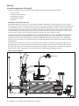
Harvest system diagram
Ice Transport Tube
Auger
Compression
Nozzle
Water Inlet

14 HC_1810R/N, HC_2110R/N, HM_1810R/N, HM_2110R/N
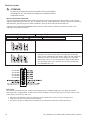
Water system
The water level in the evaporator is controlled by a feed solenoid and level detecting sensors. Referencing the
diagram below, water sensing probes extend down into the reservoir at the end of the evaporator assembly.
The system works via electrical conductivity as follows:
The probe labeled B is the common. When water is between any of the other probes and the common, the PC
board will sense the activation. During normal operation, the water level rises and falls between the Normal
High and Normal Low probes. As water is consumed to make ice, the level will fall until the Normal Low probe is
exposed, triggering the water feed solenoid on. Water will fill until the Normal High sensor is activated.
Note: The potable water total dissolved solids (TDS) content must be greater than 10 ppm for the water control
system to function properly. If using reverse osmosis water filtration system, ensure TDS level is greater
than 10 ppm.
Water system diagram
Water level diagram
Common
Normal Hi
Normal Lo
Normal
Operating
Range

HC_1810R/N, HC_2110R/N, HM_1810R/N, HM_2110R/N 15
“Bin full” detection system
The Follett Horizon ice machine incorporates a unique “bin full” detection system that consists of the shuttle
and actuator. The shuttle incorporates a flag and switch. Referencing the figure below, the normal running
position of the flag is down, and the switch is closed. When the bin fills to the top and ice can no longer move
through the tube, the machine will force the shuttle flag up, opening the switch and shutting the machine off.
The shuttle actuator, located above the ice bin allows the ice to curl up within it when the bin is full. In this way,
there are no loads generated that would tend to lift off the lid of the bin.
Running
Off
Running
Off
Shuttle flag and sensor
Shuttle actuator

16 HC_1810R/N, HC_2110R/N, HM_1810R/N, HM_2110R/N
Electrical system
ATTENTION!
To prevent circuit breaker/Hi-amp overload, wait 5 minutes before
restarting this unit. This allows the compressor to equalize and the
evaporator to thaw.
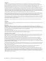
Normal control board operation
The PC board indicator lights provide all the information necessary to determine the machine's status. Green
indicator lights generally represent “go” or normal operation; Yellow indicators represent normal off conditions;
Red indicators generally represent alarm conditions, some of which will lock the machine off.
A flashing green light labeled POWER indicates power to the machine. All other normal operation status
indicators are covered as follows:
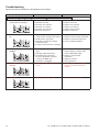
Ice machine disposition Operating conditions
FLASHINGON or OFF
Legend:
OFFON
1. Ice machine is making ice.
.
1. Normal running.
2. Ice machine is not making ice.
2. Normal time delay. When the bin fills with ice, the LOW BIN
light goes out momentarily and the refrigeration and auger
drive systems immediately shut down. (Note: The fan motor will
continue to run for 10 minutes to cool condenser) The TIME
DELAY light comes on, initiating the time delay period. When
the time delay expires, the machine will restart provided that
the LOW BIN light is on.
DIP Switch Settings
SET TO OFF
SET TO OFF
SET TO OFF
SET TO OFF
SET TO OFF
Error faults:
The Horizon PC board monitors various operating parameters including high pressure, auger gearmotor
amperage limits, clogged drain, and low water alarm conditions. There are three types of errors namely “soft”
(time delay) "hard" (reset), and “run”.
§ Soft errors will automatically reset after the 1 hour time delay or can be reset by cycling power.
§ Hard errors must be reset on the control board.
§ Run errors will give an indication of a problem, but will allow continuous normal operation.

HC_1810R/N, HC_2110R/N, HM_1810R/N, HM_2110R/N 17
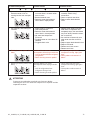
Soft errors:
HI AMPS: The PC board monitors the amperage of the auger motor. Should the gear motor experience
current draw above the allowable limit, the machine will shut down and the TIME DELAY and HI AMP will be
illuminated. After the time delay the machine will restart and the TIME DELAY and HI AMP will clear.
LO WATER: During operation, the water level cycles between the normal low and normal high sensors. Should
the water be shut off to a running machine, a soft error will occur. The error sequence is as follows: During
operation, the water level falls to the normal low sensor, and when it does the water feed solenoid is energized.
If water is not detected at the normal low sensor within 10 seconds, a soft error will occur. The machine will
shut down, but the water feed solenoid will remain energized. Should water return, it will fill to the normal low
sensor and the machine will resume normal operation. The error will clear automatically.
HI PRESSURE: Should the refrigeration pressure rise above 425 psi, the machine will shut down and the TIME
DELAY and HIGH PRESSURE will be illuminated. After the time delay, and if the pressure has fallen back below
the reset point of 295 psi, the machine will restart and the TIME DELAY and HIGH PRESSURE will clear.
Water feed error: While in making ice mode, if the water level does not fall below the low probes for 9 minutes,
the machine will enter a 1-hour time delay soft error with the LOW WATER light flashing. After the time delay
expires, the machine will try to make ice.
SERVICE: The sensor, located in the chassis will detect the presence of water just below the top edge of the
chassis.
Hard error:
HI AMPS will light as a hard error if the gearmotor circuit is open (zero current draw). Press reset on the control
board to clear this error.
Run errors:
DRAIN CLOG: When the machine shuts down on a full bin and there has been 30 minutes of cumulative
compressor run time, the machine will purge before starting. During this purge, if water does not get below the
low probe in the reservoir within 20 seconds, the Drain Clog LED will light. The machine will continue to run but
this is an indication of a poorly draining machine and must be addressed.
Relay output indication:
Each relay on the board has an indicator light associated with its output. For example, when the relay for the
water feed solenoid is energized, the adjacent indicator light glows green.
Evaporator flushing sequence:
During operation, the purge solenoid will open in order to drain water. There are two drain settings to choose
from: High TDS or Low TDS. (There is a rocker switch behind the front cover of the machine.) The intent is to
drain the Total Dissolved Solids from the machine while it makes ice.
While ice is being made, the TDS of the water in the evaporator increases in TDS concentration. Without
periodic draining, the TDS levels will climb to very detrimental levels, levels that will cause scale to form and
cause poor machine operation. The Low TDS setting will allow the machine to operate for one hour before
going through the flushing sequence; the High TDS setting will allow the machine to run for 10 minutes before
going through the flushing sequence.
The flushing sequence toggles the purge and fill solenoids three times. That is, the purge solenoid will energize
until the water level drops below the low probe. The fill solenoid then energizes until water reaches the high
probe, and so on for 3 cycles.
Typically, High TDS might be considered levels above 200 PPM, but local experience and varying water
chemistry may compel a High TDS setting for best performance in even lower TDS levels.
Off cycle: At the completion of off-cycle time delay, the machine checks for a cumulative 30 minutes of ice
making time since the last off-cycle flush. If the cumulative ice making time exceeds 30 minutes, the machine
will open the drain valve for 60 seconds to drain the evaporator in its entirety. It will then refill with water and
begin making ice. If the ice making time is less than 30 minutes, the machine will start and begin making ice
without draining the evaporator.

18 HC_1810R/N, HC_2110R/N, HM_1810R/N, HM_2110R/N
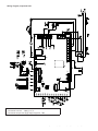
Wiring diagram, evaporator unit
Gearmotor data
Gearmotor current 4.0A @ 115 V
Gearmotor torque-out (high amp) trip point: 7.0A

HC_1810R/N, HC_2110R/N, HM_1810R/N, HM_2110R/N 19
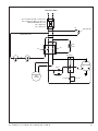
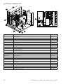
Single-phase condensing unit wiring diagram
208-230V/1/60Hz
5
2
1
RUN 1
RUN 2
μF START
15 kΩ-1W
COMPRESSOR
C
S
R
LPC
C
CCH
HPC
CC
AR
HC
HIGH LIMIT 80F
PTC
CIRCUIT BREAKER (by others)
CONDENSER
FAN
MOTOR
Start Relay
NOTE: MAKE CONNECTIONS AT
CONTACTOR LUGS
45A for MTZ36-1AV
45A for MTZ44-1AV
(Danfoss MTZ36-1AV) MOP = 45; MCA = 26.2
(Danfoss MTZ44-1AV) MOP = 45; MCA = 27.1

20 HC_1810R/N, HC_2110R/N, HM_1810R/N, HM_2110R/N
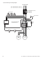
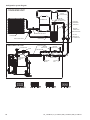
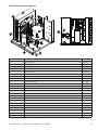
3-phase condensing unit wiring diagram
T3
T2
T1
COMPRESSOR
208-230V/3/60Hz
CONDENSER
FAN
MOTOR
CC
AR
LPC
C
HPC
PHASE MONITOR
HC
HIGH LIMIT 80F
CCH
PTC
CIRCUIT BREAKER (by others)
NOTE: MAKE CONNECTIONS
AT CONTACTOR LUGS
25A for MTZ36-3AV
30A for MTZ44-3AV
(Danfoss MTZ36-3AV) MOP = 25; MCA = 15.7
(Danfoss MTZ44-3AV) MOP = 30; MCA = 19.9
La pagina si sta caricando...
La pagina si sta caricando...
La pagina si sta caricando...
La pagina si sta caricando...
La pagina si sta caricando...
La pagina si sta caricando...
La pagina si sta caricando...
La pagina si sta caricando...
La pagina si sta caricando...
La pagina si sta caricando...
La pagina si sta caricando...
La pagina si sta caricando...
La pagina si sta caricando...
La pagina si sta caricando...
La pagina si sta caricando...
La pagina si sta caricando...
La pagina si sta caricando...
La pagina si sta caricando...
La pagina si sta caricando...
La pagina si sta caricando...
La pagina si sta caricando...
La pagina si sta caricando...
La pagina si sta caricando...
La pagina si sta caricando...
La pagina si sta caricando...
La pagina si sta caricando...
La pagina si sta caricando...
La pagina si sta caricando...
La pagina si sta caricando...
La pagina si sta caricando...
La pagina si sta caricando...
La pagina si sta caricando...
-
 1
1
-
 2
2
-
 3
3
-
 4
4
-
 5
5
-
 6
6
-
 7
7
-
 8
8
-
 9
9
-
 10
10
-
 11
11
-
 12
12
-
 13
13
-
 14
14
-
 15
15
-
 16
16
-
 17
17
-
 18
18
-
 19
19
-
 20
20
-
 21
21
-
 22
22
-
 23
23
-
 24
24
-
 25
25
-
 26
26
-
 27
27
-
 28
28
-
 29
29
-
 30
30
-
 31
31
-
 32
32
-
 33
33
-
 34
34
-
 35
35
-
 36
36
-
 37
37
-
 38
38
-
 39
39
-
 40
40
-
 41
41
-
 42
42
-
 43
43
-
 44
44
-
 45
45
-
 46
46
-
 47
47
-
 48
48
-
 49
49
-
 50
50
-
 51
51
-
 52
52


Follett Horizon Elite HC Series Operation And Service Manual
- Categoria
- Fabbricatori di cubetti di ghiaccio
- Tipo
- Operation And Service Manual
in altre lingue
- English: Follett Horizon Elite HC Series
Documenti correlati
Altri documenti
-
 SIMAG SDE18 Manuale del proprietario
-
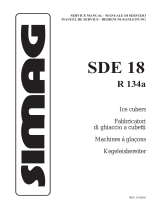 SIMAG SDE24 Manuale del proprietario
-
Hoshizaki KM-1300SAH-E Manuale utente
-
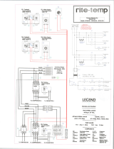 rite-temp DCS8-12 Informazioni sul prodotto
-
Stoelting SO218B Manuale utente
-
-
-
Sub-Zero 5230780 Manuale utente
-
Sterling Sterltronic S-Series Manuale utente
-


