La pagina si sta caricando...

Modelli 2404/2408
Regolatori PID
Manuale di
Installazione e Configurazione
ITA


Installation and Operation Handbook Addendum 1
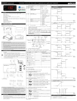
March, 98 Applies to 2408 and 2404 controller software versions 3.06 and 3.56 1
ADDENDUM ALLA VERSIONE 6 del Manuale 2408 e 2404
Sono stati inseriti nuove prestazioni sui regolatori serie 2400, i quali verranno inseriti nella nuova
versione software.
• Versione 3.06 per Regolatori e Programmatori 2404 e 2408 con 4 programmi
• Versione 3.56 per Programmatori 2404 e 2408 con 20 programmi
•
Programmer Power Output in End Segment
The Power Level in a programmer end segment can now be hidden or made read only.
A new parameter, End.P ( Power level in end segment) has been added in the Output List. This
parameter is applied when the Program End Segment is configured as SO P (Set Output Power). It can
only be adjusted when the programmer is in Hold or Reset.
The parameter Pwr has now been replaced by End.P.
Pages affected 2-13, 5-16, 2-11, 2-16
Pages 2-13 and 5-16. The parameter Pwr - (Power level in end segment) has been removed from the
Program edit list.
oP
LiSt
Output
List
HC.db
0.0
Sb.OP
100.0
End.P
0.0
Page 2-11.
A parameter
End.P Power
Level in End
Segment is added
to the Output List
Page 2-16.
A parameter
End.P Power
Level in End
Segment is added
to the Output List
oP Output list
HC.DB
Heat/cool deadband
End.P
Power level in
programmer end
segment
Sb.OP
Sensor break output
power
Note:
The End.P parameter is now a single value for all
programs.

Installation and Operation Handbook Addendum 1
2 Part Number HA025132 001
Sensor break impedance parameter, ImP.
This parameter can now be set to OFF for all input types. The controller will be shipped defaulted to
Auto i.e. enabled.
Pages affected 6-9, 6-18 .
The table on both pages appears as follows:
iP
Input configuration
Values
Meaning
imp
Sensor Break Impedance
Off
Disabled (applies to any input)
Caution:
If sensor break is disabled the controller will
not detect open circuit faults.
Auto
Factory set
Hi
Impedance of input > 5KΩ
Hi.Hi
Impedance of input > 15KΩ
All other parameters remain unchanged.
Proportional cooling option ProP .
This option has been removed from the CooL configuration table.
Page affected 6-7
inSt
Instrument configuration
CooL
Type of cooling
Lin
Linear
oiL
Oil (50mS minimum on-time)
H2O
Water (non-linear)
FAn
Fan (0.5S minimum on-time)
on.OF
On/off cooling
All other parameters remain unchanged.
Pyrometer Emmisivity
Controllers which are specifically supplied for pyrometer inputs (not Exergen K80), have the curve
downloaded in the Custom Input. The parameter, EmiS, Pyrometer Emmisivity, appears in the Input
List on page 2-15. This parameter is also now correctly adjusted.
Range
If a decimal point was configured, negative display and setpoint ranges were limited to -99.9 in previous
software versions. The range has been increased to -199.9 by combining the negative sign with the figure
one. This allows Setpoints, Process Variables, Alarm Setpoints and Programmers to be set to -199.9.
Tightening Torque of Screw Terminals
The rear terminal screws should be tightened to a torque of 0.4Nm (3.5lb in).

Installation and Operation Handbook Addendum 2
2408 Controller Part No. HA025132ENG002 Issue 1.0 1
Addendum 2 Applies to 2408 Instruments only:
New Sleeve Design MkIII
This addendum applies to:-
2408
Controllers
Manufactured from Jan-03
Installation & Operation Handbook part no.
HA025132 iss 8.1 applies
The month and year of
manufacture are shown in
the last two pairs of digits
of the instrument serial
number.
From Jan-03 an improved design of 1/8 DIN sleeve will be shipped with all new 2408
controllers and indicators.
Details
A new sealing gasket will be fitted onto the instrument bezel c. This gasket replaces the
gasket which was moulded into the front of the sleeve of all previous instruments.
The gasket previously moulded into the sleeve where it fits behind the panel is now supplied
as a separate item d.
Reasons for the Change
This change is to ensure that IP65 sealing is reliably achieved and less physical effort is
required to insert the instrument into the new sleeve.
Recommendations
1. An instrument delivered after Jan 03 should be used with the sleeve supplied
2. Removing the gasket c to fit a new instrument in an older sleeve will not guarantee
IP65 performance
3. If the instrument is required to replace one already in use, the existing sleeve must
also be replaced
4. An existing instrument can be fitted into a new sleeve but IP65 sealing will not be
maintained
The seal supplied as a separate item, should be placed over the sleeve prior to mounting it
through the panel cut out as shown below:-
Panel
Instrument
Sleeve seal d (supplied
as a separate item)
Instrument
sleeve
New seal c fitted
onto bezel

A
ddendum 2 Installation and Operation Handbook
2 Part No. HA025132ENG002 Issue 1.0 2408 Controlle
r

Installation and Operation Handbook Addendum 3
2408 and 2404 Controller Part No. HA025132ENG002 Issue 1.0 1
Addendum 3 Applies to 2408 and 2404 Controllers
Enhancements to Software Version 4
Standard controllers – which include programmers with up to 4
programs
Version 4.11
Setpoint programming controllers up to 20 programs Version 4.61
Profibus controllers - which include programmers with up to 4
programs
Version 4.32 is a PROFIBUS-DP slave device – default address 126
(decimal)
Version 4.32
The following enhancements have been added:-
Isolated single Logic Output Module
Transducer Power Supply Module to provide 5 or 10Vdc to an external transducer
DeviceNet Communications
Linear over range limits are now +5% of high instrument range and -5% of low
instrument for all process input ranges (i.e. 0-20mA, 4-20mA, 0-10V)
Sensor break or input open circuit faults are now detected on all analogue inputs (PV1,
PV2 and remote input channels)
PV2 alarm, full scale high and low limits now default to maximum and minimum display
limits
Deviation alarms are now not inverted when direct acting control is selected. Alarm
behaviour when using reverse acting control is unchanged
The PD Track, (Pd.tr) valve-positioning parameter has been removed.
Related Information
DeviceNet Communications Handbook Part Number HA027506 issue 1.0. which includes the
parameter address map.
This handbook is also available on the Eurotherm web site //http//www.eurotherm.co.uk/pdfs.

A
ddendum 3 Installation and Operation Handbook
2 Part No. HA025132ENG002 Issue 1.0 2408 and 2404 Controlle
r
MODULE WIRING CONNECTIONS
MODULE CONFIGURATION
Enter configuration level as described in the Installation and Operation Handbook, Chapter 6.
Configuration of the Isolated Logic Output
The configuration is the same as for the non-isolated Logic Output module described in
Chapter 6 of the above handbook.
Configuration of the Transducer Power Supply
To configure the choice of output voltage; 5 or 10Vdc:-
Do This The Display You
Should See
Additional Notes
The Transducer Power Supply module
can be fitted in positions 1, and 2.
The display will show 1A, or 1B
accordingly
1. Press
as many times
as necessary to select
the slot position in which
the Transducer Power
Supply module is fitted
2. Press
to read the
identity of the module
3. Press
(twice) to read
‘SEnS’
4. Press
or to
select ‘inv’ or ‘nor’
1a
ConF
This is read only where:
SG.SU = Transducer Power Supply
inv = 10Vdc nor = 5Vdc
!
The Transducer Power Supply uses
existing software written for digital
modules. A list of parameters follow which
are not applicable to this module. It
should be noted, however, that, for the
output voltage to be set as above, all of
the parameters which follow ‘SenS’ should
be set to ‘no’.
SEnS
inv
id
SG.SU
Isolated Logic Output
This is a fully isolated module which can be
fitted into module slots 1, 2 or 3. It may be
used for heating, cooling or event outputs up
to 18Vdc at 20mA.
_
+
Output
Common
Slot Position
1 2 3
1A 2A 3A
1B 2B 3B
1C 2C 3C
1D 2D 3D
Transducer Power Supply
This provides fully isolated 5 or 10Vdc to
power external transmitters up 20mA. It
can be fitted in module slots 1 and 2.
_
+
Output
Common
Slot Position
1 2
1A
2A
1B 2B
1C 2C
1D 2D

Installation and Operation Handbook Addendum 3
2408 and 2404 Controller Part No. HA025132ENG002 Issue 1.0 3
DEVICENET WIRING CONNECTIONS
Terminal
Reference
CAN
Label
Color
Chip
Description
HA V+ Red DeviceNet network power positive terminal. Connect the
red wire of the DeviceNet cable here. If the DeviceNet
network does not supply the power, connect to the positive
terminal of an external 11-25 Vdc power supply.
HB CAN_H White DeviceNet CAN_H data bus terminal. Connect the white
wire of the DeviceNet cable here.
HC SHIELD None Shield/Drain wire connection. Connect the DeviceNet
cable shield here. To prevent ground loops, ground the
DeviceNet network in only one location.
HD CAN_L Blue DeviceNet CAN_L data bus terminal. Connect the blue
wire of the DeviceNet cable here.
HE V- Black DeviceNet network power negative terminal. Connect the
black wire of the DeviceNet cable here. If the DeviceNet
network does not supply the power, connect to the
negative terminal of an external 11-25 Vdc power supply.
HF Connect to instrument earth
Note: Power taps are recommended to connect the DC power supply to the
DeviceNet trunk line. Power taps include:
A Schottky Diode to connect the power supply V+ and allows for multiple power
supplies to be connected.
2 fuses or circuit breakers to protect the bus from excessive current which could damage
the cable and connectors.
The earth connection, HF, to be connected to the main supply earth terminal.
!
V+ 5
CAN-H
CAN-L
Drain
V- 1
Red
Wht
Blu
Blk
Typical Interface
Card
(
MASTER
)
Network Supply
24Vdc ( +
1%)
250mV p-p
Ripple
V-
V+
Daisy chain to further instruments
121
terminating
resistor
required if not
fitted internally
Typical DeviceNet Wiring
Diagram
Fit 121Ω
terminating
resistor to
last
instrument
in the chain
HA
HB
HC
HD
HE
HF
Controller 0
(SLAVE)
Address 11
V+
CAN-H
CAN-L
Drain
V-
L
N
E
HA
HB
HC
HD
HE
HF
Controller 1
(SLAVE)
Address N+1
121
V+
V-
L
N
E

A
ddendum 3 Installation and Operation Handbook
4 Part No. HA025132ENG002 Issue 1.0 2408 and 2404 Controlle
r
DEVICENET CONFIGURATION
To configure Function, Baud Rate, Resolution and Node Address:-
Do This Display View Additional Notes
Node Address is set up in Operator or Full level
Exit configuration level as described in the Installation and Operation Handbook, Chapter 6.
Then:-
This is the position in which the
DeviceNet module is fitted
1. Press
as many times as
necessary to select ‘HA’.
2. Press
to read ‘id’
3. Press
to read ‘Func’
4. Press
to read ‘Baud’
5. Press
or to select
the baud rate
6. Press
to read ‘rES
7. ’ Press
or to select
‘FuLL’ or ‘Int’
If the module is present
‘id’ = Cms (digital communications)
or ‘none’ if the module is not present
Baud rate can be set to 125(K),
250(K) or 500(K)
If the DeviceNet module is fitted
‘Func’ = ‘dnEt’ and will be read
only
HA
ConF
id
cms
Func
dnEt
bAud
500
rES
FuLL
‘FuLL’ the decimal point position is
implied, eg 100.1 is transmitted as
1001.
‘Int’ rounded to the nearest the
integer value
1. Press as many times as
necessary to select ‘cms’.
2. Press to read ‘Addr’
3. Press
or to select
address
4. Press
to read ‘nw.St’
Valid addresses are from 0 - 63
cmS
LiSt
Addr
5
nw.St
run
Indicates the network status:-
‘run’ = network connected and
operational
‘rdy’ = network connected but not
operational
OFF.L’ = network not connected

Manuale di Installazione e Uso Addendum 4
2408f and 2404f Profibus regolatore HA026296ITA Versione 1.0 dicembre-97 1
Manuale Aggiuntivo per i Regolatori 2408f e 2404f
Istruzioni per i Collegamenti e il Setup Profibus-DP
Introduzione
Il 2408f e 2404f sono versioni speciali dei
regolatori Eurotherm 2408 e 2404
appositamente realizzate per comunicazioni
ProfiBus-DP. I regolatori ‘standard’ 2408 o
2404 non possono essere aggiornamente alla
versione 2408f o 2404f perché la scheda
microprocessore di questi ultimi è diversa.
Il 2408f e 2404f ProfiBus-DP è disponibile
con alimentazione da 85 a 264Vac o 20-
29Vac/dc.
Al di là delle restrizioni elencate di seguito,
le funzioni operative e i collegamenti del
2408f e del 2404f sono identiche a quelle dei
modelli standard 2408 e 2404.
Al posto delle comunicazioni ProfiBus-DP
può essere utilizzate quella Modbus, da
installare nel modulo slot H.
• Non è supportato il protcollo EI
Bisynch, e non è dunque utilizzabile il
sistema di programmazione Eurotherm
IPSG.
• Non è disponible l’opzione 20
programmi.
• I moduli di Ingresso/Uscita (I/O)
PDSIO possono essere installati solo
nello slot J.
Profibus-DP
Proibus-DP è uno standard industriale di
network aperto usato per collegare
periferiche semplici in una macchina o in un
impianto di produzione. E’ spesso usato per
permettere a un Programmable Logic
Controller o a un sistema di controllo su PC
di usare dispositivi ‘slave’ esterni per gli I/O
o per funzioni speciali. In questo modo i
dispositivi possono essere distribuiti in un
sistema di macchinari risparmiando sui costi
di collegamento punto – punto. La natura
aperta del network consente l’uso di
apparecchiature realizzate da terze parti.
Inoltre, l’off-loading di task speciali come il
controllo PID della temperatura riduce il
carico di programmazione sul PLC centrale,
permettendo lo svolgimento di altre funzioni
in modo agevole.
Profibus-DP è descritto in DIN 19245 Part
3, e fa parte di EN50170.
Il network Profibus-DP utilizza una versione
ad alta velocità dello standard RS485 sino a
12Mbaud. Il 2408f e il 2404f supporta sino
a 1.5 Mbaud per essere conforme agli
standard di isolamento elettrico. Si veda
inoltre la tavola relativa alla velocità del
network rispetto alla lunghezza della linea.
Sino a 32 Profibus FMS, stazioni (nodi)
possono essere collegati a un solo network.
L’uso dei ripetitori RS485 permette di
collegare sino a 127 stazioni.
Esistono anche il Profibus FMS, per
comunicazioni di livello più alto. Come nei
sistemi PLC e SCADA, e Profibus PA, che
possiede un medium fisico intrinsecamente
sicuro a bassa velocità ed è utilizzato
nell’Industria di Processo. Il 2408f e il
2404f possono essere utilizzati in un
network combinato DP e FMS condividendo
così lo stesso medium fisico, ma possono
essere usati solo per il PA quando non viene
utilazzato il medium intrinsecamente sicuro.
Profbus-DP è un network di tipo token
passing multimaster, master-slave. Il 2408f
e il 2404f funzionano come unità slave
intelligente. Ulteriori informazioni, inclusa
la guida ai prodotti, possono essere ottenute
dalle organizzazioini mondiali di utenti
Profibus, o su Internet
(http://www.profibus.com
)

Manuale di Installazione e Uso Addendum 4
2
2408f and 2404f Profibus regolatore HA026296ITA Versione 1.0 dicembre-97
Specifiche Tecniche
Medium Fisico 2-wire RS485
Topologia del Network Bus lineare con terminazione attiva a entrambe le estremità
L’uso delle linee stub è consentito se sono di lunghezza < 6.6m
Protocollo Profibus-DP, slave intelligente
Baud Sino a 1,5Mb/s
Numero di stationi 32 per segmento network. Sino a 127 con ripetitori
Collegamenti Elettrici
Ultima stazione
HF Digital Ground
HB
HA
HC
HE
HD
Rx/Tx +ve
Rx/Tx -ve
Scherm
VP (+5Vdc )
Stazione 1
HF
HB
HA
HC
HE
HD
390Ω
390Ω
220Ω
Solo l’ultima stazione
richiede la terminazione
Twisted pairs
Schermo
B A
B A
B A
Non collegato
Rx/Tx +ve
Rx/Tx -ve
Digital Ground
Scherm
VP (+5Vdc )
Non collegato
Stazione intermedia
2408f o 2404f regolatore
2408f o 2404f regolatore

Manuale di Installazione e Uso Addendum 4
2408f and 2404f Profibus regolatore HA026296ITA Versione 1.0 dicembre-97 3
Specifiche di Cablaggio
Si veda la tabella qui sotto. I tipi di cavo A e B NON si riferiscono ai cavi A e B nel
diagramma precedente. Il Tipo A è consigliato perché permette una maggiore velocità e una
maggiore lunghezza dei cavi.
Tipo A Tipo B
Impedenza
da 135 a 165Ω con
frequenza da 3 a 20 MHz.
da 135 a 165Ω con frequenza > 100 kHz
Capacità dei
cavi:
< 30 pF per Metre typ. < 60 pF per Metre
Diametro
interno:
max. 0.34 mm², cioè
AWG 22
max. 0.22 mm², cioè AWG 24
Tipo di cavo: Coppia intrecciata. Linee
1x2 o 2x2 o 1x4
Coppia intrecciata. Linee 1x2 o 2x2 o 1x4
Resistenza: < 110 Ohm per km -
Schermatura: In rame. Oppure con
lamine di schermatura
In rame. Oppure con lamine di schermatura
Maximum line length per segment
Baud (kbit/sec)
9.6 19.2 93.75 187.5 500 1500
Cavo Tipo A
1200m 1200m 1200m 1000m 400m 200m
Cavo Tipo B
1200m 1200m 1200m 600m 200m -
Belden B3079A è conforme alle specifiche del tipo A, ma ci sono altre possibilità. Si veda
‘Profibus Product Guide’ a cura del Profibus User Group.

Manuale di Installazione e Uso Addendum 4
4
2408f and 2404f Profibus regolatore HA026296ITA Versione 1.0 dicembre-97
Configurazione del Regolatore e Indirizzo dei Nodi
Una volta collegato il regolatore al network, dev’essere configurato per la comunicazioni
Profibus, e devono essere assegnati gli indirizzi dei nodi.
Configurazione Regolatore Assegnamento indirizzi nel nodo
Nota: Il baud rate è selezionato in modo automatico.
HA
ConF
id
CmS
Func
ProF
rEs
FULL
Lista configurazione comms - HA
Riferisi al manuale principaleper
come selezionare il livello di
configurazione e accesso nella HA
lista
Identificatore del modulo
Parametro di solo lettura
Nella list HA selezionare Func = ProF.
Risoluzione
FuLL = Full, Int = Integer
Questo parametro compare solo
quando viene selezionato la
funzione Prof.
Funzione
Selezionare Func = Prof per
Profibus
cmS
LiSt
Addr
1
Stat
run
Lista di comunicazione
Dalla HOME display,
premere
fino a quando
non compare cmS lista
Indirizzo nel nodo
Premere
per visualixxare
del nodo.
Premere
o per
selezionare l’indrizzo
desiderato.
Stato della comunicazione
Parametro diagnostico di
solo lettura
rdy pronto per run
run comunicazione
attivatà
Riferirsi al manuale principale come
selezionare e modificare il parametro.

Manuale di Installazione e Uso Addendum 4
2408f and 2404f Profibus regolatore HA026296ITA Versione 1.0 dicembre-97 5
Configurazione del network
Una volta collegato e configurato il regolatore, il pacchetto di supervisione PLC o su PC va
configurato in modo da impostare i parametri che esso sarà in grado di leggere, e ai quali
scriverà. Questa fase è la configurazione del network.
Il network si configura importando i file ‘GSD’ nel software di configurazione Master
Profibus: Vedi per dettagli la documentazione allegata al software stesso. ‘GSD’ è una sigla
indicante i ‘Database delle Periferiche’.
I file GSD per i regolatori 2408f e 2404f si creano usando un tool di configurazione a su
Windows. Fornito separatamente e rispondente al codice d’ordine PROF-ENG. Viene
fornito anche un Manuale (part number HA026290) con informazioni dettagliate.
Sul disco si trovano 2 file GSD standard.
EURO2400.GSD- Mappatura standard dei parametri
EURD2400.GSD- Mappatura standard dei parametri con ‘richiesta di dati’, che
permette la scrittura/lettura di anche dal regolatore.
I file di cui sopra possono essere modificati, e se ne possono creare di nuovi usando il
configuratore: vedi manuale.
Il software di configurazione del master Network usa i file GSD per creare un ulteriore file da
scaricare nel master PLC o nel pacchetto di supervisione PC. Dopo aver scaricato il file di
configurazione, potrete impostare il network per il funzionamento. In caso di buon
funzionamento si vedrà lampeggiare la luce ‘REM’ a indicare che lo scambio di dati è in
corso. Il parametro stat nella lista cms indicherà run. Potrete scrivere alle uscite
Profibus e leggere i dati dagli ingressi Profibus, a seconda della strategia adottata.
Si veda anche, in caso di problemi, la sezione di’troubleshooting’ alla pagina successiva.
Errore. L’oggetto incorporato non è valido.
How many parameters can I select?
How many parameters can I select?
Click on the tabs at the bottom of
the device parameter window to
select a parameter page. Then use
the mouse to drag a required
parameters into either the Profibus
input or output lists.
How do I use it?
How do I use it?
Windows configurator
Windows configurator
Windows 3.1, Windows 95, or
Windows NT.
What can I run it on?
What can I run it on?
Up to 117 per node, total of inputs and
outputs.
What does it do?
What does it do?
It creates a ‘GSD’ file which defines
the inputs and outputs that the PLC or
supervisory package will be able to
talk to. The GSD file is imported into
a Profibus Master configuration tool
which in-turn produces a file that is
downloaded into the PLC or
supervisory package.

Manuale di Installazione e Uso Addendum 4
6
2408f and 2404f Profibus regolatore HA026296ITA Versione 1.0 dicembre-97
Troubleshooting
Assenza di Comunicazione:
• Controllate attentamente collegamenti, con particolare attenzione per la continuità dei
collegamenti A e B al Master e dei morsetti relativi.
• Accedere alla lista Ha al livello di configurazione e assicurarsi che func sia impostato
su prof.
Altrimenti, il regolatore non è configurato per Profibus.
• Controllare che l’Indirizzo di Nodo (Addr) nella lista cms sia adatto alla
configurazione in uso.
• Assicurarsi dell’installazione del Profibus Comms Module nello slot H del 2404/8f.
• Assicurarsi della corretta configurazione del network e della sua corretta trasmissione al
master Profibus.
• Verificare che il file GSD sia corretto caricandolo nel tool di Configurazione del master
GSD. Verrà controllato il formato.
• Verificare che la lunghezza max. di linea per la rampa baud non venga superata (vd.tav).
La rampa massima per il 2404/8f è di 1.5Mbaud.
• Assicurarsi che l’ultimo dispositivo nel segmento di network sia terminato correttamente
(vd.schema).
• Assicurarsi che non ci siano dispositivi diversi da quelli al termine del segmento dotati di
terminazioni network.
• Sostituite, in caso di bisogno, i dispositivi difettosi
Guasti di comunicazione intermittenti.
Passaggi di status intermittenti da rdy a run.
Cambiamento di status diagnostico non connesso ad allarmi.
• Verificare i collegamenti, con particolare attenzione alla schermatura.
• La lunghezza dei dati I/O potrebbe essere eccessiva.
Alcune implementazioni Profibus DP Master non accettano più di 32 word di ingresso e
32 di uscita per ogni slave. Si vedano i documenti relativi al Master.
• Verificare che la lunghezza max. di linea per la rampa baud non venga superata (vd.
specifiche di cablaggio). La rampa massima per il 2404/8f è di 1.5Mbaud.
• Assicurarsi che l’ultimo dispositivo nel segmento di network sia terminato correttamente
(vd. schema).
• Assicurarsi che non ci siano dispositivi diversi da quelli al termine del segmento dotati di
terminazioni network.
• Sostituite, in caso di bisogno, i dispositivi difettosi.
EUROTHERM CONTROLS
SUB24/PB PROFIBUS Iss No.
AH026222 U002 DATE

Manuale di Installazione e Uso Contenuti
Versione 6B Novembre 07 2408 e 2404 regolatore. Valido per la versione 3.0 e 3.5 i
MODELLI 2408 e 2404 PID REGOLATORE
MANUALE DI INSTALLAZIONE E USO
Contenuti Page
Capitolo 1 INSTALLAZIONE 1-1
Capitolo 2 FUNZIONAMENTO 2-1
Capitolo 3 LIVELLI DI ACCESSO 3-1
Capitolo 4 TUNING 4-1
Capitolo 5 FUNZIONAMENTO DEL PROGRAMMATORE 5-1
Capitolo 6 CONFIGURAZIONE 6-1
Capitolo 7 CALIBRAZIONE UTENTE 7-1
REQUISITI DI SICUREZZA A-1
RoHS B-1
“Questo prodotto è coperto da uno o più diritti:
5,484,206;Diritti aggiuntivi
PDSIO e INSTANT ACCURACY sono esclusiva Eurotherm”

Contenuti Manuale di Installazione e Uso
ii Versione 6B Novembre 07 2408 e 2404 regolatore. Valido per la versione 3.0 e 3.5

Manuale di Installazione e Uso Installazione
Regolatore 2408 e 2404 1-1
Capitolo 1 INSTALLAZIONE
Figura 1-1 Regolatore 2408 1/8 DIN
Figura 1-2 Regolatore 2404 1/4 DIN
Clip di fissaggio del pannello
Denti d’arresto
Custodia
Coperchi morsettiere
Etichetta
Linguette di chiusura
Guarniz. Chiusura Ermetica Pannello
Display
Clip di fissaggio del pannello
Denti di arresto
Custodia
Coperchio morsettiere
Etichetta
Linguette di
chiusura
Guarnizione di chiusura ermetica del pannello
Display

Installazione Manuale di Installazione e Uso
1-2 Regolatore 2408 e 2404
Dimensioni esterne del Modello 2408
Dimensioni esterne del Modello 2404
L’assemblaggio elettronico del regolatore si inserisce in una custodia di plastica rigida che a sua volta si
adatta alla foratura di pannello di sez. standard DIN vista in Figura 1-3 e 1-4.
2408
OP 1 OP2
SP2 REM
AUTO
MAN
RUN
HOLD
Figura 1-3
Dimensioni esterne del Regolatore modello 2408
150mm
5.91in
48mm
1.89in
96mm
3.78in
Foratura
Pannello
92 x 45mm
3.62x1.77in
-0
+0.8
-0
+0.6
-0
+0.03
-0
+0.02
38mm
(1.5in)
10mm
(0.4in)
(Non
Scalare)
Spaziature minime
consigliate del
regolatore
150mm
5.91in
96mm
3.78in
96mm
3.78in
2404
OP 1
OP2
SP2
REM
AUTO
MAN
RUN
HOLD
Foratura
Pannello
92 x 92 mm
3.62 x 3.62 in
-0 +0.8
-0 +0.03
Spaziature
minime
consigliate del
regolatore
38mm
(1.5in)
10mm
(0.4in)
(Non
Scalare)
Figura 1-4 Dimensioni esterne del regolatore Modello 2404
1/120