
I
T
A
L
I
A
N
O
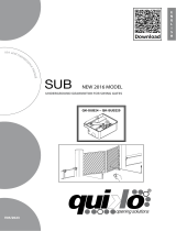
UNDERGROUND GEARMOTOR FOR SWING GATES
u
s
e
a
n
d
m
a
i
n
t
e
n
a
n
c
e
m
a
n
u
a
l
QK-SUB24 – QK-SUB220
SUB
E
N
G
L
I
S
H
V03/2016
NEW 2016 MODEL

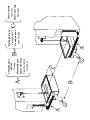
A
A
B
C
Centro scatola
Center box
Centro de la caja
Centre box
Drenaggio acqua
Drainage water
Drenaje de aqua
Aqua vidange
Canalizzazione
elettrica
Trunking
Alcantarilla para
Cables electricos
Egout de cables
electriques
ABC

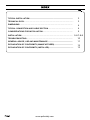
TYPICAL INSTALLATION......................................................................................
3
TECHNICAL DATA.................................................................................... 3
DIMENSIONS ......................................................................................... 4
TYPICAL CONNECTION AND CABLE SECTION.......................................... 4
CONSIDERATIONS FOR INSTALLATION................................................... 5
INSTALLATION.......................................................................................
5-6-7-8-9
TROUBLESHOOTING............................................................................... 10
GENERAL ADVICE, USE AND MAINTENANCE..................................................
11
DECLARATION OF CONFORMITY (MANUFACTURER)..................................... 12
DECLARATION OF CONFORMITY (INSTALLER)................................................
12
13
www.quikoitaly.com

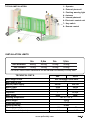
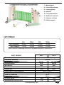
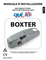
TECHNICAL DATA
Max. weight of leaf See installation limits table
Max. width of leaf 3,50 mt
Motors power supply 24 Vdc 230 Vac
Motor power 50 W 280 W
Motor RPM 1800 1400
Capacitor / 12,5 µF
Max. Thrust 300N
Working temperature -30° C / +70° C
Motor weight 10 Kg
Protection rating IP 67
Opening time 90° 16 sec
Current absorbed (motor) 3 A 1.4 A
230V24V
5
1
1
2
2
3
4
5
6
7
8
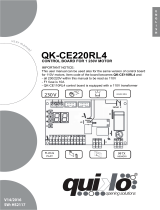
TYPICAL INSTALLATION 1- Operator
2- External photocell
3- Flashing warning light
4- Antenna
5- Internal photocell
6- Electronic control unit
7- Key-switch
8- Remote control
Working cycle (%) 100 50
380N
3m
2m 2,5m 3,5m
400kg
300kg
QK-SUB220 500kg
400kg
600kg
500kg
800kg
700kg
QK-SUB24
The values shown within table above can be reduced considerably in windy areas
INSTALLATION LIMITS
www.quikoitaly.com

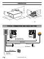
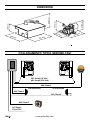
DIMENSIONS
TYPICAL CONNECTION AND CABLE SECTION
2X1,5mm2 (24 Vdc )
4X1,5mm2 (230 Vca )
2X0,75mm2
4X0,75mm2
4X0,75mm2
2X0,75mm2
3X1,5mm2
230V Line
RX Photocell TX Photocell
230 mm
375 mm
320 mm
165 mm
11 mm 9
329 mm
227 mm
141 mm
www.quikoitaly.com

INSTALLATION
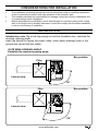
CONSIDERATIONS FOR INSTALLATION
Introductory note: Dig a hole big enough to hold the foundation box, calculate the
required opening angle,
insert the sheath for laying the power cable, make water drainage holes in the
ground and cement the box solidly.
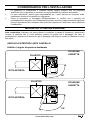
GATE WING OPENING ANGLE
Establish the required opening angle
90°
110°
Pillar
Pillar
Internal view
Internal view
Box position
·The installation and testing operations must be performed solely by qualified personnel in
order to guarantee the proper and safe operation of the automatic gate.
· The company declines any responsibility for damage caused by incorrect installations due
to incompetence and/or negligence.
·Before assembling the automatism, check that the gate is in perfect working order, hangs
well on its hinges and is suitably lubricated. It must also comply with the safety standards
in force in the country of installation..
Box position
www.quikoitaly.com

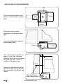
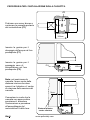
BOX INSTALLATION PROCEDURE
Dig a hole big enough to hold
the box containing the operator
(C1)
Insert the tube for water
drainage in the prepared hole
(F1)
Insert the sheath for laying the
power cables (F2).
Note: while positioning the box,
keep in mind the minimum
distance there must be between
the pillar and the centre of
rotation of the gate hinge.
Cement so that the box cannot
be moved, wait for it to dry and
then assemble the operator and
levers.
Distance between
Pillar - Hinge Centre
375mm
320mm
C1
F 2
F 1
165mm
75mm
www.quikoitaly.com

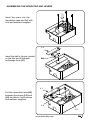
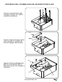
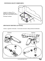
ASSEMBLING THE OPERATOR AND LEVERS
Insert the motor into the
foundation case and fixit with
nuts and washers supplied
Insert the ball in the pin located
on the box and fit the gate
anchorage lever (L1)
Put the connection lever(L2)
between the levers (L3) and
(L4) and block it with screws
and washers supplied
BALL
L 1
L 1
L 2
L 3
www.quikoitaly.com

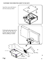
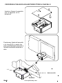
FASTENING THE OPERATOR LEVER TO THE GATE
Insert the cover and fasten it
with the screws provided
Position the gate wing and the
lever (L1) so that they are
perfectly aligned and fasten
them by welding or similar.
welding
Gate wing
L 1
www.quikoitaly.com

Insert the key C provided into
the appropriate hole on the
lever L1
Turn the key
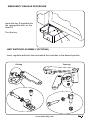
EMERGENCY RELEASE PROCEDURE
LIMIT SWITCHES ASSEMBLY (OPTIONAL)
Insert, regulate and block the mechanical limit switches in the desired position
OpeningClosing
L 1
V
C
www.quikoitaly.com

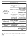
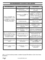
TROUBLESHOOTING
PROBLEM PROBABLE CAUSE SOLUTION
On giving a command with
the remote
control or with the
key-switch, the gate
doesn’t open or the motor
doesn’t start
230 volt mains voltage
absent Check master switch
Emergency STOP present
Check for any STOP
selectors or commands.
If not used, check jumper
on STOP contact input on
the control board
Fuse blown Replace with one of same
value.
Power cable of motor or
motors not
connected or faulty.
Connect the cable to
appropriate
terminal or replace.
The photocell is not
functioning or the
beam is interrupted
Check the connection,
remove any
obstacle across the beam
On giving a command with
the remote control, the
gate doesn’t open but
works with the key
command
The remote control has not
been
memorised or the battery
is flat
Carry out the remote
control learning
procedure on the radio
receiver or replace the
battery with a new one..
The gate starts, but stops
immediately
The force of the motor or
motors is insufficient
Modify the value with the
FORCE trimmer on the
control unit
One wing opens and the
other closes
The connection is not
correct
Invert the connection of
the cable of the motor
which rotates in the wrong
sense
N.B. - If the problem persists, contact your Retailer or the nearest Service
Centre
www.quikoitaly.com

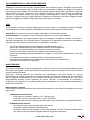
MAINTENANCE
Actuators need very little maintenance; however their function depends also on the gate conditions,
hence here are operations to be done to keep the gate efficient at all times.
Warning: no one but the maintenance man, who must be a specialized technician, must be able to
control the automatic gate while it is being serviced. For this reason please turn off electricity,
avoiding also electric shocks hazard. If on the contrary electricity must be on for certain checks,
remember to check or disable any control device (remote controls, push button panels etc.) except
the one used by the service man.
Routine maintenance
Each of the following operations must be done when needed and in all cases at least every 6 months:
1) Mechanical maintenance
- Lubricate (with oilier) the hinges on which the gate swings;
- check the good conditions of brackets and motor’s hinges;
- do an unlocking operation to be sure the mechanism is always efficient.
2) Electrical maintenance
- Check the proper working of the safety devices;
- check the electronic friction’s efficacy;
- check the earth system’s (differential’s) efficacy. Try the differential switcher once a month
by pushing the special test button on the switcher.
GENERAL ADVICE
Install a gate’s safety system that complies with current regulations. Choose short routes for cables
and keep power cables separate from control ones. Install the control card in a waterproof box.
Please refer to current regulations when setting the gear motor’s maximum torque.
We advice you to install an outdoor switch, in compliance with European standards on the issue of
safety, to turn the electricity off when servicing the gate.
Check that each single installed device is efficient and effective.
Affix easily readable signs warning about the presence of a motorized gate.
USE
It is absolutely forbidden to use the device for any other purposes. The installed electronic unit (which
must have built-in electric friction), allows to select the following functions:
automatic: one control impulse will open or close the gate;
semi-automatic: one control impulse will open or close the gate.
In case of blackout, act on the manual unlocking device and move manually the gate. Remember that
this is an automatic device powered by electricity, consequently use with care. In particular,
remember:
- not to touch the device with wet hands and/or wet or bare feet;
- to turn off electricity before opening the control box and/or actuator;
- not to pull the lead to pull the plug out;
- to put the gate in movement only when it is completely visible;
- to keep out of the gate’s range of action if it is moving. Wait until it has stopped;
- not to let children or animals play near the gate;
- not to let children use the remote control or other operating devices;
- to carry out routine maintenance;
- in case of failure, to turn off electricity and operate the gate manually only if it is possible and
safe. Refrain from touching the gate and call an authorized technician.
www.quikoitaly.com

E
N
G
L
I
S
H
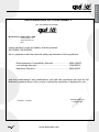
DECLARATION OF CONFORMITY
(OF THE MANUFACTURER)
Manufacturer: QUIKO ITALY SAS
hereby declares, under his liability, that the products:
QK-SUB24, QK-SUB220
are in compliance with the essential safety requirements of the regulations:
Electromagnetic Compatibility Directive .........................2004/108/EC
Low Voltage Directive ......................................................2006/95/EC
Machinery Directive .........................................................2006/42/EC
and their amendments and modifications, and with the regulations set forth by the
National Legislative Body of the country in which the machinery is destined for use.
Via Seccalegno, 19
36040 Sossano (VI)
Italia
Managing Director
Luca Borinato
Sossano, 1/1/2016
2www.quikoitaly.com

DECLARATION OF CONFORMITY
(OF THE INSTALLER)
The undersigned:
in charge of the set-up, declares that the product:
Gate type:
are in compliance with the essential safety requirements of the regulations:
Electro magnetic Compatibility Directive .........................2004/108/EC
Low Voltage Directive ............................................................2006/95/EC
Machinery Directive ................................................................2006/42/EC
and also declares that the related and/or specific national technical regulations have been
followed:
EN 12453/EN 12445 on Industrial, Commercial and Residential Gates and Doors – Safe
Use of Motorized Doors – Requirements and Classification – Test Methods;
EN 12604/ EN 12605 on Industrial, Commercial and Residential Gates and Doors –
Mechanical Aspects – Requirements and Classification – Test Methods;
CEI 64/8 Electrical Systems Using Nominal Tension Not Higher Than 1000V a.c. and 1500
V d.c.;
EN 13241-1 (Industrial, commercial and garage doors and gates), conformity evaluation
(6.3).
Notes:
Place and date: ………………………………………
3
www.quikoitaly.com

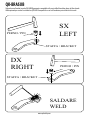
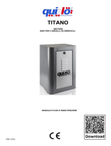
SX
LEFT
DX
RIGHT
SALDARE
WELD
STAFFA / BRACKET
PERNO / PIN
STAFFA / BRACKET
PERNO / PIN
QK-BRASUB
Optional curved bracket to make QK-SUB220 gearmotor compatible with pre-installed foundation boxes of other brands
Staa opzionale per rendere il motoriduttore QK-SUB220 compatibile con casse di fondazione preinstallate di altri marchi
www.quikoitaly.com

Quiko Italy
Via Seccalegno, 19
36040 Sossano (VI) - Italy
Tel. +39 0444 785513
Fax +39 0444 782371
info@quiko.biz
www.quikoitaly.com

I
T
A
L
I
A
N
O
m
a
n
u
a
l
e
d
’
u
s
o
e
m
a
n
u
t
e
n
z
i
o
n
e
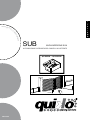
AUTOMAZIONE INTERRATA PER CANCELLI A BATTENTE
SUB
V03/2016
NUOVA VERSIONE 2016
QK-SUB24 – QK-SUB220

A
A
B
C
Centro scatola
Center box
Centro de la caja
Centre box
Drenaggio acqua
Drainage water
Drenaje de aqua
Aqua vidange
Canalizzazione
elettrica
Trunking
Alcantarilla para
Cables electricos
Egout de cables
electriques
ABC

Impianto tipo......... ............................................................................. 3
Dati tecnici .......................................................................................... 3
Dimensioni .......................................................................................... 4
Collegamento tipo e sezione cavi ...................................................... 4
Considerazione per l’installazione ...................................................... 5
Modalità’ di installazione ..................................................................... 5-6-7-8-9
Inconvenienti : cause e soluzioni....................................................... 10
Raccomandazioni, uso e manutenzione............................................. 11
www.quikoitaly.com

1- Motoriduttori
2- Fotocellula esterna
3- Lampeggiatore
4- Antenna
5- Fotocellula interna
6- Quadro di comando
7- Selettore a chiave
8- Radiocomando
5
1
1
2
2
3
4
5
6
7
8
LIMITI D’IMPIEGO
DATI TECNICI
Peso Max anta Vedi tabella limiti d’impiego
Lunghezza Max anta 3,50 mt
Alimentazione motore 24 Vdc 230 Vac
Potenza motore 50 W 280 W
Giri motore 1800 1400
Condensatore / 12,5 µF
Coppia max
Temperatura di funzionamento -30° C / +70° C
Peso 10 Kg
Grado di protezione IP 67
Tempo di apertura 90° 16 sec
Forza di spinta 100%
Assorbimento medio motore 3 A 1.4A
230V24V
50%
300N 380N
3m
2m 2,5m 3,5m
400kg
300kg
QK-SUB220 500kg
400kg
600kg
500kg
800kg
700kg
QK-SUB24
I valori mostrati in tabella possono ridursi considerevolmente in aree ventose
www.quikoitaly.com
La pagina si sta caricando...
La pagina si sta caricando...
La pagina si sta caricando...
La pagina si sta caricando...
La pagina si sta caricando...
La pagina si sta caricando...
La pagina si sta caricando...
La pagina si sta caricando...
La pagina si sta caricando...
La pagina si sta caricando...
La pagina si sta caricando...
La pagina si sta caricando...
-
 1
1
-
 2
2
-
 3
3
-
 4
4
-
 5
5
-
 6
6
-
 7
7
-
 8
8
-
 9
9
-
 10
10
-
 11
11
-
 12
12
-
 13
13
-
 14
14
-
 15
15
-
 16
16
-
 17
17
-
 18
18
-
 19
19
-
 20
20
-
 21
21
-
 22
22
-
 23
23
-
 24
24
-
 25
25
-
 26
26
-
 27
27
-
 28
28
-
 29
29
-
 30
30
-
 31
31
-
 32
32


in altre lingue
- English: quiko Sub User manual
Documenti correlati
-
 quiko Sub Manuale utente
-
 quiko SCARABEO Manuale utente
-
 quiko SCARABEO Manuale utente
-
 quiko SCARABEO Manuale utente
-
 quiko QK-CE220BATRL4 Manuale utente
-
 quiko QK-CE220RL4 Manuale utente
-
 quiko QK-CE220RLINV Manuale utente
-
 quiko EON110 Manuale utente
-
 quiko BOXTER+CE220BASC Manuale utente
-
 quiko TITANO+QK-CE220RLX(V05) Manuale utente


