

Table of Contents
PAGE II
I. ABOUT THE WIRELESS AIR VELOCITY SENSOR 1
ALTA WIRELESS SENSOR FEATURES 1
EXAMPLE APPLICATIONS 1
II. ORDER OF OPERATIONS 2
III. SETUP AND INSTALLATION 3
REGISTER THE SENSOR 3
IV. SETTING UP YOUR AIR VELOCITY SENSOR 5
INSTALLING BATTERIES 5
MOUNTING THE SENSOR 6
ANTENNA ORIENTATION 6
V. SENSOR OVERVIEW IN iMONNIT 7
MENU SYSTEM 7
VI. ACTIONS OVERVIEW 11
CREATING AN ACTION 11
VII. SECURITY 15
SENSOR TO GATEWAY 15
GATEWAYTO iMONNIT 15
iMONNIT 15
SENSOR PRINTS 15
SUPPORT 16
WARRANTY INFORMATION 16
CERTIFICATIONS 18
SAFETY RECOMMENDATIONS 20

I. ABOUT THE WIRELESS AIR VELOCITY SENSOR
The ALTA Wireless Air Velocity Sensor measures the pressure difference between two input
ports, the temperature, and altitude determines the speed at which the air is moving in a
system and transmits the measurement to iMonnit.
PAGE 1
ALTA WIRELESS SENSOR FEATURES
- Wireless range of 1,200+ feet through 12+ walls *
- Frequency-Hopping Spread Spectrum (FHSS)
- Interference immunity
- Power management for longer battery life **
- Encrypt-RF® Security (Diffie-Hellman Key Exchange + AES-128 CBC for sensor data
messages)
- Onboard data memory stores up to hundreds of readings per sensor:
- 10-minute heartbeats = 3.5 days
- 2-hour heartbeats = 42 days
- Over-the-air updates (future proof)
- Free iMonnit basic online wireless sensor monitoring and notification system to
configure sensors, view data and set alerts via SMS text and email
*Actual range may vary depending on environment.
**Battery life is determined by sensor reporting frequency and other variables. Other power options are also available.
EXAMPLE APPLICATIONS
- Building/Room Pressure
- Air Flow
- Variable Air Volume Filter Status
- Duct Pressure
- Clean Rooms
- Hospitals
- Fume Hoods
- Computer Rooms
- Additional applications
- Measurement range: -50 m/s to 50 m/s
- Calibrated and temperature compensated
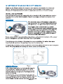
The sensor measures the pressure difference between two ports. When viewing the sensor
from the top, the right inlet port is the positive or high side pressure input. When the
pressure on this port is greater than the left port the sensor produces a negative pressure
reading. When the pressure is greater on the left port the sensor produces a positive
pressure reading. Combined with the temperature and the altitude, the sensor determines
at what rate the air is flowing in a system.

PAGE 2
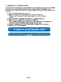
II. ORDER OF OPERATIONS
It is important to understand the order of operations for activating your sensor. If performed
out of sequence, your sensor may have trouble communicating with iMonnit. Please
perform the steps below in the order indicated to make sure you are performing your set-up
correctly.
1. Create iMonnit Account (If new user).
2. Register all sensors and gateways to a network in iMonnit.
Sensors can only communicate with gateways on the same iMonnit
network.
3. Connect/power on gateway and wait till it checks into iMonnit.
4. Power on sensor and verify it checks into iMonnit.
We recommend powering the sensor on near the gateway then moving to the
installation location, checking signal strength along the way.
5. Configure sensor for use (This can be done at any point after step 2)
6. Install sensor in final location.
Note: Device specific setup is covered in more detail in the following
sections.
Note: For information on setting up iMonnit and the gateway refer to
the iMonnit User Guide and the gateways user guide.

PAGE 3
III. SETUP AND INSTALLATION
If this is your first time using the iMonnit online portal, you will need to create a new
account. If you have already created an account, start by logging in. For instructions on how
to register and setup your iMonnit account, please consult the iMonnit User Guide.
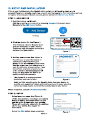
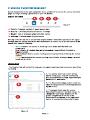
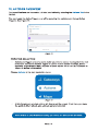
STEP 1: ADD DEVICE
1. Add the sensor on iMonnit.
Add the sensor to your account by choosing Sensors in the main menu.
Navigate to the Add Sensor button.
2. Find the device ID. See Figure 1.
The Device ID (ID) and Security Code
(SC) are necessary to add a sensor.
These can both be located on the label
on the side of your device.
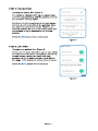
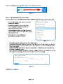
3. Adding your device. See Figure 2.
You will need to enter the Device ID
and the Security Code from your
Sensor in the corresponding text boxes.
Use the camera on your smartphone to
scan the QR code on your device. If you
do not have a camera on your phone,
or the system is not accepting the QR
code, you may enter the Device ID
and Security Code manually.
- The Device ID is a unique number
located on each device label.
- Next, you?ll be asked to enter the Security Code from your device. A
security code consists of letters and must be entered in upper case (no
numbers). It can also be found on the barcode label of your device.
When completed, select the Add Device button.
Figure 1
Figure 2
Desktop Mobile
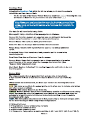
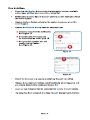
Select your use case. See Figure 3.
Unlike most sensors, choosing a use case in
Step 2 of adding this sensor does not give
you the option to customize your settings.
These will need to be adjusted in the settings
tab for your device. See page 9 for
instructions.
Select the Skip button when completed.
STEP 2: SETUP
Figure 3

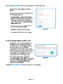
Check your signal. See Figure 4.
The validation checklist will help you ensure your
sensor is communicating with the gateway properly
and you have a strong signal.
Checkpoint 4 will only complete when your sensor
achieves a solid connection to the gateway. Once
you insert the batteries (or flip the switch on an
industrial sensor) the sensor will communicate with
the gateway every 30 seconds for the first few
minutes.
Select the Save button when completed.
STEP 3: VALIDATION
Figure 4
STEP 4: ACTIONS
Choose your actions. See Figure 5.
Actions are the alerts that will be sent to your phone
or email in the event of an emergency. Low battery
life and device inactivity are two of the most
common actions to have enabled on your device.
See page 12 for how to set actions for your sensor.
Select the Done button when completed.
Figure 5
PAGE 4

IV. SETTING UP YOUR AIR VELOCITY SENSOR
When you are finished adding the sensor to your account, the next step is to insert the
battery. The type of battery you use will depend on the category of your sensor. ALTA
Wireless Air Velocity Sensors will either be powered by a AA or an industrial battery.
PAGE 5
INSTALLING BATTERIES
ALTA commercial sensors are powered by AA or industrial 3.6V Lithium batteries supplied
from Monnit or another battery supplier. Monnit encourages customers to recycle all old
batteries.
AA Batteries
The standard version of this sensor is powered by
two replaceable 1.5 V AA sized batteries (included
with purchase). The typical battery life is 10 years.
This sensor is also available with a line power
option. The line powered version of this sensor has
a barrel power connector allowing it to be powered
by a standard 3.0?3.6 V power supply. The line
powered version also uses two standard 1.5 V AA
batteries as backup for uninterrupted operation in
the event of line power outage.
Power options must be selected at time of purchase, as the internal hardware of the sensor
must be changed to support the selected power requirements.
Place batteries in the device by first taking the sensor and sliding the battery door open.
Insert fresh AA batteries in the carriage, then shut the battery door.
Complete the process by opening up iMonnit and selecting Sensors from the main navigation
menu. Verify that iMonnit is showing the sensor has a full battery level.
Industrial Batteries
3.6V Lithium batteries for the Industrial Wireless Air
Velocity Sensor is supplied by Monnit. The ALTA
battery life for the Industrial battery is up to 7 years.
Industrial batteries should not be removed from the
device or replaced.
In order for the sensor to function properly, you will
need to attach the included antenna. Simply screw the
antenna onto the barrel connector on the top of the
device. Make sure the antenna connection is snug, but
Figure 6
Figure 7
Figure 8

Since the electronics are sealed within the sensor housing, we have added an "On/Off"
switch to the unit for your convenience. If you are not using the sensor, simply leave the
button in the off position to preserve battery life. If the sensor needs to be reset for any
reason, you can simply cycle the power by turning the switch to the "Off" position and
waiting 30 seconds before powering back on.
MOUNTING THE SENSOR
Monnit wireless sensors feature mounting flanges and can be attached to most surfaces
using the included mounting screws or double-sided tape.
PAGE 6
do not over tighten. When placing the sensor, make sure to mount the sensor with the
antenna oriented straight up (vertical) to ensure the best wireless radio signal.
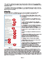
ANTENNA ORIENTATION
In order to get the best performance out of your ALTA Wireless Sensors, it is important to
note proper antenna orientation and sensor positioning. Antennas should all be oriented in
the same direction, pointing vertically from the sensor. If the sensor is mounted flat on its
back on a horizontal surface, you should bend the antenna as close to the sensor housing
as possible giving you the most amount of antenna pointing vertical. You should make the
antenna wire as straight as possible, avoiding any kinks and curving of the wire. Sensors
must be at least 3 ft. away from other sensors and the wireless gateway to function.
More Signal
Less Signal
Figure 9
Figure 10

PAGE 7
V. SENSOR OVERVIEW IN iMONNIT
Select Sensors from the main navigation menu on iMonnit to access the sensor overview
page and begin making adjustments to your Tilt Sensor .
MENU SYSTEM
A. Details - Displays a graph of recent sensor data
B. History - List of all past heartbeats and readings
C. Events - List of all events attached to this sensor
D. Settings - Editable levels for your sensor
Directly under the tab bar is an overview of your sensor. This allows you to see the signal
strength and the battery level of the selected sensor. A colored dot in the left corner of the
sensor icon denotes its status.
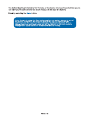
Details View
The Details View will be the first page you see upon selecting which sensor you would like
to modify.
A. The sensor overview section will be
above every page. This will consistently
display the present reading, signal strength,
battery level, and status.
B. The Recent Readings section below the
chart shows your most recent data received
by the sensor.
C. This graph charts how the sensor
fluctuates throughout a set date range. To
change the date range displayed in the
graph, navigate up to the top of the
Readings Chart section on the right-hand
corner to change the from and/or to date.
- Green indicates the sensor is checking in and within user-defined safe
parameters.
- Red indicates the sensor has met or exceeded a user-defined threshold or
triggered event.
- Gray indicates that no sensor readings are being recorded, rendering the sensor
inactive.
- Yellow indicates that the sensor reading is out of date, due to perhaps a missed
heartbeat check-in.
A
B
C
A B C D
Figure 11
Figure 12

Readings View
Selecting the Readings Tab within the tab bar allows you to view the sensor?s
data history as time stamped data.
- On the far right of the Sensor History Data is a cloud icon. ( ) Selecting this icon
will export an Excel file for your sensor into your download folder.
The data file will have the following fields:
MessageID: Unique identifier of the message in our database.
Sensor ID: If multiple sensors are exported, you can distinguish between the
sensors using this number ? even if the names are the same.
Sensor Name: The name you have given the sensor.
Date: The date the message was transmitted from the sensor.
Value: Data presented with transformations applied, but without additional
labels.
Formatted Value: Data transformed and presented as it is shown in the
monitoring portal.
Raw Data: Raw data as it is stored from the sensor.
Sensor State: Binary field represented as an integer containing information
about the state of the sensor when the message was transmitted. (See
?Sensor State? explained below.)
Alert Sent: Boolean indicating if this reading triggered a notification to be sent
from the system.
Sensor State
The value presented here is generated from a single byte of stored data.
A byte consists of 8 bits of data that we read as Boolean (True (1) / False (0))
fields.
When broken into individual bits, the State byte contains the following information:
aaaabcde
STS: This value is specific to the sensor profile and is often used to indicate error states
and other sensor conditions.
UNUSED: This sensor does not use these bits.
AWARE: Sensors become aware when critical sensor specific conditions are met. Going
aware can cause the sensor to trigger and report before the heartbeat and cause the
gateway to forward the data to the server immediately resulting in near immediate
transmission of the data.
TEST: This bit is active when the sensor is first powered on or reset and remains active
for the first 9 messages when using default configurations.
STS Specific Codes:
0 = No problems, sensor is functioning normally.
1 = Open circuit detected in lead.
2 = Short circuit detected in lead.
3 = Range error. Temperature is reading outside of -40 F and 257 F (-40 C and 125 C).
Note: Make sure you have the date range for the data you need input
in the ?From? and ?To? text boxes. This will be the previous day by
default. Only the first 2,500 entries in the selected date range will be
exported.
PAGE 8

PAGE 9
Settings View
To edit the operational settings for a sensor, choose the ?Sensor? option in the main
navigation menu then select the ?Settings? tab to access the configuration page.
A. Sensor Name is the unique name you give
the sensor to easily identify it in a list and in any
notifications.
B. Heartbeat Interval is how often the sensor
communicates with the gateway if no activity is
recorded.
C. Aware State Heartbeat is how often the
sensor communicates with the gateway while in
an Aware State.
D. Assessments Per Heartbeat is how many
times between heartbeats a sensor will check its
measurements against its thresholds to
determine whether it will enter the Aware State.
E. Below is the lowest allowable value for the
sensor.
F. Above is the highest allowable value for the
sensor.
G. Aware State Buffer is a buffer to prevent the
sensor from bouncing between Standard
Operation and Aware State when the
assessments are very close to a threshold.
H. Altitude is the set altitude of the sensor.
I. Show Temperature shows the temperature
with an air pressure reading.
J. Synchronize is a setting that in small sensor
networks synchronizes communication. The
default setting OFF allows the sensors to
randomize their communications therefore
maximizing communication robustness. Setting
this will synchronize the communication of the
sensors.
K. Failed transmissions before link mode is the number of transmissions the sensor
sends without response from a gateway before it goes to battery saving link mode. In link
mode, the sensor will scan for a new gateway and if not found will enter battery saving
sleep mode for up to 60 minutes before trying to scan again. Lower numbers will allow
sensors to find new gateways with fewer missed readings. Higher numbers will enable the
sensor to remain with its current gateway in a noisy RF environment better (Zero will cause
the sensor to never join another gateway to find a new gateway, the battery will have to be
cycled out of the sensor.)
If the user has calibrated the sensor, the Calibrate Active field is set to False (0) and the
sensor is operating inside the Min and Max Thresholds, the bits look like 00000000, this is
represented as 0.
If the sensor is using factory calibrations and it is outside the threshold, the bit values are
00010010 and are represented as 18(16+2 because both the bit in the 16 value is set and
the bit in the 2 value is set).
A
B
C
DE
F
G
H
I
JK
Figure 13

PAGE 10
Note: Be sure to select the Save button anytime you make a change to any of
the sensor parameters. All changes made to the sensor settings will be
downloaded to the sensor on the next sensor heartbeat (check-in). Once a
change has been made and saved, you will not be able to edit that sensor?s
configuration again until it has downloaded the new setting.
The default heartbeat interval is 120 minutes or two hours. It is recommended that you do
not lower your heartbeat level too much because it will drain the battery.
Finish by selecting the Save button.

VI. ACTIONS OVERVIEW
Device notifications can be created, deleted, and edited by selecting the Actions Tab in the
tab bar.
You can toggle the Action Trigger on or off by selecting the switch under Current Action
Triggers. See Figure 14.
CREATING AN ACTION
- Actions are triggers or alarms set to notify you when a sensor reading identifies that
immediate attention is needed. Types of actions include sensor readings, device
inactivity, and scheduled data. Any one of these can be set to send a notification or
trigger an action in the system.
Choose Actions in the main navigation menu.
-
-
- A list of previously created actions will display on the screen. From here, you have
the ability to filter, refresh, and add new actions to the list.
Note: If this is your first time adding an action, the screen will be blank.
Figure 14
Figure 15
PAGE 11

From the Actions page, tap Add Action in the left hand corner.
Step 1: What triggers your action?
The drop-down menu will have the following options for Action Types (See Figure 17):
- Select Sensor Reading from the drop-down menu.
- A second drop-down menu will appear. From here, you will be able to see a list of
the different type of sensors registered to your account. Choose AirSpeed in the
drop-down menu.
- Choose whether you wish to detect a Airspeed or Temperature from the "Select
Reading" dropdown menu.
- Next, you will be asked to input the trigger settings. You have the option of setting
this trigger to detect greater than or less than a desired reading.
Press the Save button.
- Sensor Reading: Set actions based on
activity or reading.
- Device Inactivity: Actions when the
device doesn?t communicate for an
extended period of time.
- Advanced: Actions based on advanced
rules, such as comparing past data points
with current ones.
- Scheduled: These actions are
performed at a time set basis.
Figure 16
Figure 17
Figure 18
PAGE 12

Step 2: Actions
- Press the Add Action button under the information header, available
action types will then be presented in a select list.
- Notification Action: Specify account users to receive notification when
this event triggers.
- System Action: Assign actions for the system to process when this
event triggers.
- Choose Notification Action from the notification list.
A. Input the subject for the notification.
See Figure 19.
B. Customize the message body
for the notification. See Figure 19.
C. Recipient list identifies who will
receive the notification.
See Figure 20.
- Select the icon next to a user to specify how they will be notified.
- Choose if you want notifications sent immediately, when triggered, or if
you want a delay before sending and press Set.
- A green icon indicates that the users that will receive the notifications.
- If a delay has been selected, the delay time will display beside the icon.
Figure 19
Figure 20
A
B
C
PAGE 13

Select System Action from the Add Action list. See Figure 21.
Acknowledge: Automatically signals
that you have been notified of an action.
When an action has been triggered,
alerts will continue processing until the
action returns to a value that no longer
triggers an action.
Full Reset: Reset your trigger so it is
armed for the next reading.
Activate: Enable an action trigger.
Deactivate: Disable an action trigger.
Figure 21
Figure 22
- Scroll down to the System Action
section.
- The Action to be done select list has
the following options:
Step 3: Action Name and Devices
- By default, the sensor(s) will not be
assigned to the action conditions
you?ve just set. To assign a sensor,
find the device(s) you want to
designate for this action and select.
Selected sensor boxes will turn green
when activated. Choose the sensor
box again to unassign the sensor
from the action. See Figure 22.
- Continue toggling the sensor(s)
corresponding to this new action until
you are satisfied with your selection.
These can be adjusted later by
returning to this page.
Press the Check-mark button to complete the process.
PAGE 14

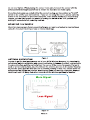
VII. SECURITY
Data security and integrity is paramount at Monnit. Each layer of the system is secured
using encryption and protocols designed to protect customer data and information. The
system consists of sensor(s), gateway(s), and iMonnit software. One or more sensors
communicate with iMonnit software through a gateway.
SENSOR TO GATEWAY
Sensor and gateway radio modules are purpose built devices with proprietary unreadable
firmware, which means the sensor cannot be physically hacked or re-purposed for
malicious purposes. This adds a strong level of inherent security even before considering
encryption. Data transmission between the sensor and gateway are secured using
Encrypt-RF Security (Diffie-Hellman Key Exchange + AES-128 CBC for sensor data
messages). Beyond the encryption, data transmissions are also structurally verified and
CRC checked before they are passed up to iMonnit or down to the sensor, this ensures the
integrity of the data itself.
GATEWAY TO IMONNIT
Data transmissions between the gateway and iMonnit software are secured using 256-bit,
bank level encryption.
iMONNIT
Access is granted through the iMonnit user interface, or an Application
Programming Interface (API) safeguarded by 256-bit Transport Layer Security (TLS 1.2)
encryption. TLS is a blanket of protection to encrypt all data exchanged between iMonnit
and you. The same encryption is available to you whether you are a Basic or Premiere user
of iMonnit. You can rest assured that your data is safe with iMonnit.
SENSOR PRINTS
Sensor prints utilize a shared key between the software and the sensor to ensure that once
the data comes to iMonnit it is guaranteed to be from the device identified by the sensor
print. If this feature is purchased for the device (via iMonnit software) the devices data
becomes impossible to spoof by any malicious device.
PAGE 15

PAGE 16
SUPPORT
For technical support and troubleshooting tips please visit our support library online at
monnit.com/support/. If you are unable to solve your issue using our online support, email
Monnit support at [email protected] with your contact information and a description of
the problem, and a support representative will call you within one business day.
For error reporting, please email a full description of the error to [email protected].
WARRANTY INFORMATION
(a) Monnit warrants that Monnit-branded products (Products) will be free from defects in
materials and workmanship for a period of one (1) year from the date of delivery with
respect to hardware and will materially conform to their published specifications for a period
of one (1) year with respect to software. Monnit may resell sensors manufactured by other
entities and are subject to their individual warranties; Monnit will not enhance or extend
those warranties. Monnit does not warrant that the software or any portion thereof is error
free. Monnit will have no warranty obligation with respect to Products subjected to abuse,
misuse, negligence or accident. If any software or firmware incorporated in any Product
fails to conform to the warranty set forth in this Section, Monnit shall provide a bug fix or
software patch correcting such non-conformance within a reasonable period after Monnit
receives from Customer (i) notice of such non-conformance, and (ii) sufficient information
regarding such non-conformance so as to permit Monnit to create such bug fix or software
patch. If any hardware component of any Product fails to conform to the warranty in this
Section, Monnit shall, at its option, refund the purchase price less any discounts, or repair
or replace nonconforming Products with conforming Products or Products having
substantially identical form, fit, and function and deliver the repaired or replacement
Product to a carrier for land shipment to customer within a reasonable period after Monnit
receives from Customer (i) notice of such non-conformance, and (ii) the non-conforming
Product provided; however, if, in its opinion, Monnit cannot repair or replace on
commercially reasonable terms it may choose to refund the purchase price. Repair parts
and replacement Products may be reconditioned or new. All replacement Products and
parts become the property of Monnit. Repaired or replacement Products shall be subject to
the warranty, if any remains, originally applicable to the product repaired or replaced.
Customer must obtain from Monnit a Return Material Authorization Number (RMA) prior to
returning any Products to Monnit. Products returned under this Warranty must be
unmodified.
Customer may return all Products for repair or replacement due to defects in original
materials and workmanship if Monnit is notified within one year of customer?s receipt of the
product. Monnit reserves the right to repair or replace Products at its own and complete
discretion. Customer must obtain from Monnit a Return Material Authorization Number
(RMA) prior to returning any Products to Monnit. Products returned under this Warranty
must be unmodified and in original packaging. Monnit reserves the right to refuse warranty
repairs or replacements for any Products that are damaged or not in original form. For
Products outside the one year warranty period repair services are available at Monnit at
standard labor rates for a period of one year from the Customer?s original date of receipt.
(b) As a condition to Monnit?s obligations under the immediately preceding paragraphs,
Customer shall return Products to be examined and replaced to Monnit?s facilities, in
shipping cartons which clearly display a valid RMA number provided by Monnit. Customer
acknowledges that replacement Products may be repaired, refurbished or tested and found
to be complying. Customer shall bear the risk of loss for such return shipment and shall
bear all shipping costs. Monnit shall deliver replacements for Products determined by
Monnit to be properly returned, shall bear the risk of loss and such costs of shipment of
repaired Products or replacements, and shall credit Customer?s reasonable costs of
shipping such returned Products against future purchases.

PAGE 17
(c) Monnit?s sole obligation under the warranty described or set forth here shall be to repair
or replace non-conforming products as set forth in the immediately preceding paragraph, or
to refund the documented purchase price for non-conforming Products to Customer.
Monnit?s warranty obligations shall run solely to Customer, and Monnit shall have no
obligation to customers of Customer or other users of the Products.
Limitation of Warranty and Remedies.
THE WARRANTY SET FORTH HEREIN IS THE ONLY WARRANTY APPLICABLE TO
PRODUCTS PURCHASED BY CUSTOMER. ALL OTHER WARRANTIES, EXPRESS OR
IMPLIED, INCLUDING BUT NOT LIMITED TO THE IMPLIED WARRANTIES OF
MERCHANTABILITY AND FITNESS FOR A PARTICULAR PURPOSE ARE EXPRESSLY
DISCLAIMED. MONNIT?S LIABILITY WHETHER IN CONTRACT, IN TORT, UNDER ANY
WARRANTY, IN NEGLIGENCE OR OTHERWISE SHALL NOT EXCEED THE PURCHASE
PRICE PAID BY CUSTOMER FOR THE PRODUCT. UNDER NO CIRCUMSTANCES
SHALL MONNIT BE LIABLE FOR SPECIAL, INDIRECT OR CONSEQUENTIAL
DAMAGES. THE PRICE STATED FOR THE PRODUCTS IS A CONSIDERATION IN
LIMITING MONNIT?S LIABILITY. NO ACTION, REGARDLESS OF FORM, ARISING OUT
OF THIS AGREEMENT MAY BE BROUGHT BY CUSTOMER MORE THAN ONE YEAR
AFTER THE CAUSE OF ACTION HAS ACCRUED.
IN ADDITION TO THE WARRANTIES DISCLAIMED ABOVE, MONNIT SPECIFICALLY
DISCLAIMS ANY AND ALL LIABILITY AND WARRANTIES, IMPLIED OR EXPRESSED,
FOR USES REQUIRING FAIL-SAFE PERFORMANCE IN WHICH FAILURE OF A
PRODUCT COULD LEAD TO DEATH, SERIOUS PERSONAL INJURY, OR SEVERE
PHYSICAL OR ENVIRONMENTAL DAMAGE SUCH AS, BUT NOT LIMITED TO, LIFE
SUPPORT OR MEDICAL DEVICES OR NUCLEAR APPLICATIONS. PRODUCTS ARE
NOT DESIGNED FOR AND SHOULD NOT BE USED IN ANY OF THESE
APPLICATIONS.

CERTIFICATIONS
United States FCC
This equipment has been tested and found to comply with the limits for a Class B digital
devices, pursuant to Part 15 of the FCC Rules. These limits are designed to provide
reasonable protection against harmful interference in a residential installation. This
equipment generates, uses, and can radiate radio frequency energy and, if not installed
and used in accordance with the instruction manual, may cause harmful interference to
radio communications. However, there is no guarantee that interference will not occur in a
particular installation. If this equipment does cause harmful interference to radio or
television reception, which can be determined by turning the equipment off and on, the
user is encouraged to try to correct the interference by one of more of the following
measures:
- Reorient or relocate the receiving antenna.
- Increase the separation between the equipment and receiver
- Connect the equipment into an outlet on a circuit different from that to which the
receiver is connected.
- Consult the dealer or an experienced radio/TV technician for help.
Warning: Changes or modifications not expressly approved by Monnit could void
the user?s authority to operate the equipment.
RF Exposure
WARNING: To satisfy FCC RF exposure requirements for mobile
transmitting devices, the antenna used for this transmitter must not be
co-located in conjunction with any antenna or transmitter.
Monnit and ALTA Wireless Sensors:
This equipment complies with the radiation exposure limits prescribed for an uncontrolled
environment for fixed and mobile use conditions. This equipment should be installed and
operated with a minimum distance of 23 cm between the radiator and the body of the user
or nearby persons.
All ALTA Wireless Sensors Contain FCC ID: ZTL-G2SC1. Approved Antennas
ALTA devices have been designed to operate with an approved antenna listed below, and
having a maximum gain of 14 dBi. Antennas having a gain greater than 14 dBi are strictly
prohibited for use with this device. The required antenna impedance is 50 ohms.
- Xianzi XQZ-900E (5 dBi Dipole Omnidirectional)
- HyperLink HG908U-PRO (8 dBi Fiberglass Omnidirectional)
- HyperLink HG8909P (9 dBd Flat Panel Antenna)
- HyperLink HG914YE-NF (14 dBd Yagi)
- Specialized Manufacturing MC-ANT-20/4.0C (1 dBi 4? whip)
PAGE 18
La pagina si sta caricando...
La pagina si sta caricando...
La pagina si sta caricando...
-
 1
1
-
 2
2
-
 3
3
-
 4
4
-
 5
5
-
 6
6
-
 7
7
-
 8
8
-
 9
9
-
 10
10
-
 11
11
-
 12
12
-
 13
13
-
 14
14
-
 15
15
-
 16
16
-
 17
17
-
 18
18
-
 19
19
-
 20
20
-
 21
21
-
 22
22
-
 23
23


in altre lingue
- English: Monnit PS-AV-AUG-01 User guide
Documenti correlati
-
Monnit Alta Long range Wireless Carbon Monoxide Sensor Guida utente
-
Monnit MNS2-4-W2-PS Series Guida utente
-
-
-
Monnit Alta Guida utente
-
-
Monnit Alta 4G LTE Cellular Gateway Guida utente