Monnit Alta 4G LTE Cellular Gateway Guida utente
- Tipo
- Guida utente

IMPORTANT!
For best results, please wait to power on your LTE Cellular Gateway until after you have
registered an account on iMonnit and added your gateway and sensors to the online
system.
ALTA 4G LTE Cellular Gateway
USER GUIDE
Remote Monitoring for Business

PAGE II
Table of Contents
I. ABOUT THE LTE CELLULAR GATEWAY 1
ALTA LTE CELLULAR GATEWAY FEATURES 1
EXAMPLE APPLICATIONS 1
II. HOW YOUR GATEWAY WORKS 2
III. GATEWAY SECURITY 3
SENSOR COMMUNICATION SECURITY 3
DATA SECURITY ON THE GATEWAY 3
SERVER COMMUNICATION SECURITY 3
IV. GATEWAY REGISTRATION 4
REGISTERING THE GATEWAY 4
V. USING THE LTE CELLULAR GATEWAY 4
USING THE POWER INTERRUPT SWITCH 4
SETTING UP AND POWERING ON THE GATEWAY 5
UNDERSTANDING THE GATEWAY LIGHTS 5
LTE CELLULAR GATEWAY SETTINGS 6
SUPPORT 8
WARRANTY INFORMATION 8
CERTIFICATIONS 10
COVERAGE MAPS 13

PAGE 1
I. ABOUT THE LTE CELLULAR GATEWAY
Monnit's ALTA LTE Cellular Gateway allows you to control your sensors' settings without
additional IT infrastructure. All you need is a power source to monitor your environment
and equipment using Monnit's industry-leading devices. The LTE Cellular Gateway
communicates with sensors and iMonnit® to deliver data alerting you to conditions in a
surrounding area. LTE Cellular Gateways operate utilizing 4G LTE CAT-M1/NB1 cellular
technology.
The LTE Cellular Gateway is a specialized device with an incredible range. This advanced
wireless IoT (Internet of Things) gateway accommodates multiple vertical IoT application
segments and remote wireless sensor management solutions. Your gateway is equipped
with a 24-hour backup battery.* Monnit Wireless ALTA Sensors will continue to
communicate with iMonnit via cellular transmission in a power outage event. The LTE
Cellular Gateway is ideal for applications without an existing wired Internet connection or
where existing infrastructure is dedicated to other resources.
ALTA LTE CELLULAR GATEWAY FEATURES
- Wireless range of 1,200+ feet through 12+ walls *
- Frequency Hopping Spread Spectrum (FHSS)
- Improved interference immunity
- Encrypt-RF® Security (Diffie-Hellman Key Exchange + AES-128 CBC for sensor data
messages)
- Up to 30,000 sensor message memory
- Over-the-air updates (future proof)
- True plug & play? no hassles for Internet configuration set-up **
- No PC required for operation
- Low-cost cellular service packages
- Local status LEDs with transmission and online status indicators
- 24-hour battery backup in event of power outage
* Actual range may vary depending on environment.
** When paired with a Monnit data plan.
EXAMPLE APPLICATIONS
- Remote Location Monitoring
- Shipping and Transportation
- Agricultural Monitoring
- Vacant Property Management
- Vacation Home Property Management
- Construction Site Monitoring
- Data Center Monitoring
* Actual time may vary depending on usage.
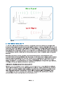
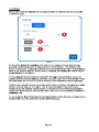
II. HOW YOUR GATEWAY WORKS
Your ALTA LTE Cellular Gateway manages communication between your sensors and
iMonnit. When running, the gateway will periodically transmit data on a heartbeat. The
gateway will store information received from sensors until its next heartbeat.
The ALTA LTE Cellular Gateway is a cellular gateway. It uses cellular towers to relay data
received from sensors to iMonnit. Sensors communicate with the gateway, then the
gateway relays information to the cloud.
For your wireless sensors to work optimally, orient all antennas for your sensor(s) and
gateway(s) the same direction (typically vertical). Sensors must also be at least three feet
away from other sensors and the wireless gateway in order to function properly.

PAGE 2
More Signal
Less Signal
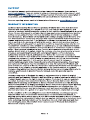
III. GATEWAY SECURITY
SENSOR COMMUNICATION SECURITY
The ALTA LTE Cellular Gateway has been designed and built to securely manage data
from sensors monitoring your environment and equipment. Hacking from botnets are in the
headlines, Monnit Corporation has taken extreme measures to ensure your data security is
handled with the utmost care and attention to detail. The same methods utilized by financial
institutions to transmit data are also used in Monnit security infrastructure. Security features
of the gateway include tamper proof network interfaces, data encryption, and bank-grade
security.
Monnit?s proprietary sensor protocol uses low transmit power and specialized radio
equipment to transmit application data. Wireless devices listening on open communication
protocols cannot eavesdrop on sensors. Packet level encryption and verification is key to
ensuring traffic isn?t altered between sensors and gateways. Paired with best-in-class
range and power consumption protocol, all data is transmitted securely from your devices.
Thereby ensuring a smooth, worry-free, experience.
Monnit sensor to gateway secure wireless tunnel is generated using ECDH-256 (Elliptic
Curve Diffie-Hellman) public key exchange to generate a unique symmetric key between
each pair of devices. Sensors and gateways use this link specific key to process packet
level data with hardware accelerated 128-bit AES encryption which minimizes power
consumption to provide industry best battery life. Thanks to this combination, Monnit
proudly offers robust bank-grade security at every level.
Figure 1

PAGE 3
DATA SECURITY ON THE GATEWAY
SERVER COMMUNICATION SECURITY
The ALTA LTE gateway is designed to prevent prying eyes from accessing the data that is
stored on the sensors. The ALTA LTE Cellular Gateway does not run on an off the shelf
multi-function OS (operating system). Instead it runs a purpose specific real-time
embedded state machine that cannot be hacked to run malicious processes. There are
also no active interface listeners that can be used to gain access to the device over the
network. The fortified gateway secures your data from attackers and secures the gateway
from becoming a relay for malicious programs.
Communication between your ALTA LTE Cellular Gateway and iMonnit is secured by
packet level encryption. Similar to the security between the sensors and gateway, the
gateway and server also establish a unique key using ECDH-256 for encrypting data. The
packet level data is encrypted end to end removing additional requirements to configure
specialized cellular VPN?s. The gateway can still operate within a VPN if it is present.
Because all traffic is initiated from the gateway there is no special IP configuration needed
for the gateway allowing it to operate with any 4G LTE CAT-M1/NB1 enabled SIM provider.
IV. GATEWAY REGISTRATION
If this is your first time using the iMonnit online portal, you will need to create a new
account. If you have already created an account, start by logging in. For instructions on
how to register for an iMonnit account, please consult the iMonnit User Guide.
REGISTERING THE GATEWAY
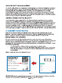
You will need to enter the Device ID and the Security Code from your LTE Cellular
Gateway in the corresponding text boxes. Use the camera on your smartphone to scan the
QR code on your Gateway. If you do not have a camera on your phone, or you are
accessing the online portal through a desktop computer, you may enter the Device ID and
Security Code manually.
- The Device ID is a unique number located on each device label.
- Next you?ll be asked to enter the Security Code (SC) on your device. A security
code will be all letters, no numbers. It can also be found on the barcode label of
your gateway.
When completed, select the ?Submit? button.
IMPORTANT: Add the gateway and all sensors to the iMonnit portal so that on boot, the
gateway can download and whitelist the sensors from the account.
Figure 2

PAGE 4
V. USING THE LTE CELLULAR GATEWAY
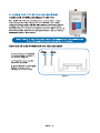
SETTING UP AND POWERING ON THE GATEWAY
1. Connect your antennas
to the gateway as seen in
the below diagram.
2. Plug the power supply
cord into an outlet.
3. After the three LED lights
switch to green, your
network is ready to use.
Figure 4
Cellular
Antenna Radio
Antenna
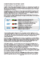
USING THE POWER INTERRUPT SWITCH
The ALTA 4G LTE Industrial Gateway comes with a power
interrupt operated by a magnetic reed switch. The power
interrupt disconnects both the main power supply and battery
backup. Use this feature if you need to force a reset of the
gateway without opening the waterproof seal. When magnetic
contact is made, gateway status lights will turn off, indicating
successful power interruption.
Note: Power is only interrupted while the magnet is on the touchpoint.
Once the magnet is removed, power is returned.
Figure 3

PAGE 5
UNDERSTANDING THE GATEWAY LIGHTS
The gateway will enter three stages as it powers on:
Power-on stage: The gateway will analyze electronics and programming. The LED lights
will flash red and green, before all becoming green for one second. In case of failure, the
light sequence will repeat after ten seconds. Please contact technical support if the lights
aren?t green after two minutes.
Connection stage: The gateway will attempt to settle all operational connections. As the
gateway first connects to the network, all other lights will be dark. A blinking green light
indicates the gateway is attempting to make a tower connection. A flashing red light is a
signal the cellular connection has encountered a problem.
Operational stage: All of the lights will remain green while powered externally, unless
there is an issue. A blinking cellular link light is a signal that the gateway has encountered
an issue in the cellular network.
Blinking Red: Cellular connection error
If your gateway is running off battery power or the device has been switched to a low
power mode, all lights are off. The sensor data light will blink green when data is received
by the gateway. The internet server light will blink every five seconds the status of the last
connection. If the light is green, the communication was good. If the light is red, the
communication failed.
Figure 5
Steady Red: Sensor communication problem.
Steady Green: Communication with sensors is OK.
Blinking Green: Active communication with sensors.
Steady Red: Last communication with Monnit?s server was
unsuccessful.
Steady Green: Last communication with Monnit?s server was OK.
Blinking Green: Active communication with Monnit?s server
Double Blinking Green: Scanning for Tower
Steady Green: Connected to the cellular network
Triple Blinking Green: Cellular Network Offline
Blinking Green / Red: Low cellular signal
Single Blinking Green: Activating Data Session
Sensor
Data
Internet
Server
Cellular
Service
On battery power or "Forced-low power" mode: If your gateway is running off battery
power or the device has been switched to a low power mode, all lights are off. The sensor
data light will blink green when data is received by the gateway. The internet server light
will blink every five seconds the status of the last connection. If the light is green, the
communication was good. If the light is red, the communication failed.
Utility button actions: The utility button can be used during the operational stage to
perform a configuration reset or a full factory reset. The configuration reset will erase all
your unique settings and return the gateway to factory default settings, while saving any
data collected by the sensors prior to the reset. The full factory reset will not only restore
default settings, but will also erase any data on the gateway.
To perform a configuration reset, the utility button is pressed for between five and ten
seconds and released as well during that window of time. After pressing the utility button
for more than five seconds, all the LEDs turn solid red and releasing the button during this
LED display will result the configuration reset.
If the utility button is held for more than ten seconds, all the LEDs will begin to blink red.
Releasing the utility button when all the LEDs are blinking red will result in a full factory
reset of the gateway, restoration of default settings, and the loss of all data in memory.

PAGE 6
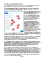
LTE CELLULAR GATEWAY SETTINGS
The LTE Cellular Gateway will receive data from all sensors assigned to the network and
within range, then return this data to the server in a series of heartbeats.
You can access gateway settings by selecting ?Gateways? in the main navigation panel.
Choose the LTE Cellular Gateway from the list of gateways registered to your account.
Select the ?Settings? tab to edit the gateway: A. The Gateway Name field is where you
assign your gateway a unique title. By
default, the gateway name will be the
type followed by the Device ID.
B. The Heartbeat Minutes configures
the interval that the gateway checks in
with the server. The default is fifteen
minutes. So every fifteen minutes your
gateway will report to the server.
C. The Global System for Mobile
Communications utilizes a fifteen digit
IMSI (International Mobile Subscriber
Identity) number as the primary mode to
identify the country, mobile network, and
subscriber. It is formatted as
MCC-MNC-MSIN. MCC is the Mobile
Country Code. MNC is the Mobile
Network Code attached to the cellular
network. MSIN is a serial number making
the IMSI unique to a subscriber.
D. The ICCID is the nineteen-digit unique
identification number corresponding to
the cellular SIM card. It is possible to change the information contained on a SIM (including
the IMSI), but the identity of the SIM itself remains the same.
E. IMEI (International Mobile Equipment Identity) is a number exclusive to your LTE Cellular
Gateway to identify the gateway to the cell tower. The Global System for Mobile
Communications network stores the IMEI numbers in their database (EIR - Equipment
Identity Register) containing all valid cellular equipment.
F. The On Aware Messages option changes the reporting behavior such that, when this
option is toggled to "Trigger Heartbeat," if the sensor(s) reach an aware state outside of the
heartbeat interval, the gateway will immediately relay that data to the server instead of
waiting the extra time it would take to reach the next heartbeat minute. If the option is
toggled to "Wait for Heartbeat," the gateway will not relay data to the server, even if
sensor(s) reach an aware state, until the next heartbeat.
G. The drop-down menu for Gateway Power Mode allows the user select between a
Standard option, a Force Low Power option, Force High Power option. When Standard is
selected, the gateway will operate in high power mode when line power is provided and low
power mode when the gateway operates on backup battery power. When Force Low
Power is selected, the gateway always operates in low power mode, even when line power
is provided, and when High Power is selected, the gateway always operates in high power
mode, even when relying on the backup battery, reducing the life of the backup battery.
H. The field for Primary Server displays the URL for the Monnit server, together with the
port used to communicate with the gateway.
Figure 6
A
B
CD
EF
G
H

PAGE 7
Commands
Choose the bullet for Commands located just under the Settings title to access the
commands page.
A. The Auto Reset field configures the interval, in number of hours, at which the
gateway automatically resets to help maintain normal function. The default is 168
hours, or one week. During an automatic reset, the sensor(s) will store all their data to
send to the gateway as soon as the reset is complete, whereupon the data is relayed
by the gateway to the server.
B. Selecting the Reform Network command will trigger the gateway to remove all
sensors from the internal whitelist, and then request a new sensor list from the server.
This command will force all sensors to reinitialize their connection with the gateway.
Reforming the network cleans up communication when multiple networks are in range
of each other so they are all in sync. This is especially useful if you must move
sensors to a new network, and would like to clear these sensors from the gateway?s
internal list. Reforming the network will place a new list of sensors that will continue to
exchange data.
C. Choosing the Reset Gateway to Factory Defaults button will erase all your unique
settings and return the gateway to factory default settings.
.
Figure 7
A
B
C

SUPPORT
WARRANTY INFORMATION
(a) Monnit warrants that Monnit-branded products (Product) will be free from defects in
materials and workmanship for a period of one (1) year from the date of delivery with
respect to hardware and will materially conform to their published specifications for a period
of one (1) year with respect to software. Monnit may resell sensors manufactured by other
entities and are subject to their individual warranties; Monnit will not enhance or extend
those warranties. Monnit does not warrant that the software or any portion thereof is error
free. Monnit will have no warranty obligation with respect to Products subjected to abuse,
misuse, negligence or accident. If any software or firmware incorporated in any Product
fails to conform to the warranty set forth in this section, Monnit shall provide a bug fix or
software patch correcting such non-conformance within a reasonable period after Monnit
receives from customer (i) notice of such non-conformance, and (ii) sufficient information
regarding such non-conformance so as to permit Monnit to create such bug fix or software
patch. If any hardware component of any Product fails to conform to the warranty in this
section, Monnit shall, at its option, refund the purchase price less any discounts, or repair
or replace nonconforming Products with conforming Products, or Products having
substantially identical form, fit, and function and deliver the repaired or replacement
Product to a carrier for land shipment to customer within a reasonable period after Monnit
receives from customer (i) notice of such non-conformance, and (ii) the non-conforming
Product provided; however, if, in its opinion, Monnit cannot repair or replace on
commercially reasonable terms it may choose to refund the purchase price. Repair parts
and replacement Products may be reconditioned or new. All replacement Products and
parts become the property of Monnit. Repaired or replacement Products shall be subject to
the warranty, if any remains, originally applicable to the Product repaired or replaced.
Customer must obtain from Monnit a Return Material Authorization Number (RMA) prior to
returning any Products to Monnit. Products returned under this warranty must be
unmodified.
Customer may return all Products for repair or replacement due to defects in original
materials and workmanship if Monnit is notified within one year of customer?s receipt of the
Product. Monnit reserves the right to repair or replace Products at its own and complete
discretion. Customer must obtain from Monnit a Return Material Authorization Number
(RMA) prior to returning any Products to Monnit. Products returned under this Warranty
must be unmodified and in original packaging. Monnit reserves the right to refuse warranty
repairs or replacements for any Products that are damaged or not in original form. For
Products outside the one year warranty period repair services are available at Monnit at
standard labor rates for a period of one year from the customer?s original date of receipt.
(b) As a condition to Monnit?s obligations under the immediately preceding paragraphs,
customer shall return Products to be examined and replaced to Monnit?s facilities, in
shipping cartons which clearly display a valid RMA number provided by Monnit. Customer
acknowledges that replacement Products may be repaired, refurbished or tested and found
to be complying. Customer shall bear the risk of loss for such return shipment and shall
bear all shipping costs. Monnit shall deliver replacements for Products determined by
Monnit to be properly returned.
PAGE 8
For technical support and troubleshooting tips please visit our support library online at
monnit.com/support/. If you are unable to solve your issue using our online support, email
Monnit support at [email protected] with your contact information and a description of
the problem, and a support representative will call you within one business day.
For error reporting, please email a full description of the error to [email protected].

(c) Monnit?s sole obligation under the warranty described or set forth here shall be to repair
or replace non-conforming Products as set forth in the immediately preceding paragraph, or
to refund the documented purchase price for non-conforming Products to customer.
Monnit?s warranty obligations shall run solely to customer, and Monnit shall have no
obligation to customers of customer or other users of the products.
Limitation of Warranty and Remedies.
THE WARRANTY SET FORTH HEREIN IS THE ONLY WARRANTY APPLICABLE TO
PRODUCTS PURCHASED BY CUSTOMER. ALL OTHER WARRANTIES, EXPRESS OR
IMPLIED, INCLUDING BUT NOT LIMITED TO THE IMPLIED WARRANTIES OF
MERCHANTABILITY AND FITNESS FOR A PARTICULAR PURPOSE ARE EXPRESSLY
DISCLAIMED. MONNIT?S LIABILITY WHETHER IN CONTRACT, IN TORT, UNDER ANY
WARRANTY, IN NEGLIGENCE OR OTHERWISE SHALL NOT EXCEED THE PURCHASE
PRICE PAID BY CUSTOMER FOR THE PRODUCT. UNDER NO CIRCUMSTANCES
SHALL MONNIT BE LIABLE FOR SPECIAL, INDIRECT OR CONSEQUENTIAL
DAMAGES. THE PRICE STATED FOR THE PRODUCTS IS A CONSIDERATION IN
LIMITING MONNIT?S LIABILITY. NO ACTION, REGARDLESS OF FORM, ARISING OUT
OF THIS AGREEMENT MAY BE BROUGHT BY CUSTOMER MORE THAN ONE YEAR
AFTER THE CAUSE OF ACTION HAS ACCRUED.
IN ADDITION TO THE WARRANTIES DISCLAIMED ABOVE, MONNIT SPECIFICALLY
DISCLAIMS ANY AND ALL LIABILITY AND WARRANTIES, IMPLIED OR EXPRESSED,
FOR USES REQUIRING FAIL-SAFE PERFORMANCE IN WHICH FAILURE OF A
PRODUCT COULD LEAD TO DEATH, SERIOUS PERSONAL INJURY, OR SEVERE
PHYSICAL OR ENVIRONMENTAL DAMAGE SUCH AS, BUT NOT LIMITED TO, LIFE
SUPPORT OR MEDICAL DEVICES OR NUCLEAR APPLICATIONS. PRODUCTS ARE
NOT DESIGNED FOR AND SHOULD NOT BE USED IN ANY OF THESE
APPLICATIONS.
PAGE 9

CERTIFICATIONS
United States FCC
This equipment has been tested and found to comply with the limits for a Class B digital
devices, pursuant to Part 15 of the FCC Rules. These limits are designed to provide
reasonable protection against harmful interference in a residential installation. This
equipment generates, uses, and can radiate radio frequency energy and, if not installed
and used in accordance with the instruction manual, may cause harmful interference to
radio communications. However, there is no guarantee that interference will not occur in a
particular installation. If this equipment does cause harmful interference to radio or
television reception, which can be determined by turning the equipment off and on, the
user is encouraged to try to correct the interference by one of more of the following
measures:
- Reorient or relocate the receiving antenna.
- Increase the separation between the equipment and receiver
- Connect the equipment into an outlet on a circuit different from that to which the
receiver is connected.
- Consult the dealer or an experienced radio/TV technician for help.
Warning: Changes or modifications not expressly approved by Monnit could void
the user?s authority to operate the equipment.
RF Exposure
Monnit and ALTA Cellular Gateways:
This equipment complies with the radiation exposure limits prescribed for an uncontrolled
environment for fixed and mobile use conditions. This equipment should be installed and
operated with a minimum distance of 23 cm between the radiator and the body of the user
or nearby persons.
PAGE 10
All ALTA Wireless Sensors and Gateways Contain FCC ID: ZTL-G2SC1.
Approved Antennas
ALTA devices have been designed to operate with an approved antenna listed below, and
having a maximum gain of 14 dBi. Antennas having a gain greater than 14 dBi are strictly
prohibited for use with this device. The required antenna impedance is 50 ohms.
- Xianzi XQZ-900E (5 dBi Dipole Omnidirectional)
- HyperLink HG908U-PRO (8 dBi Fiberglass Omnidirectional)
- HyperLink HG8909P (9 dBd Flat Panel Antenna)
- HyperLink HG914YE-NF (14 dBd Yagi)
- Specialized Manufacturing MC-ANT-20/4.0C (1 dBi 4? whip)
Monnit 4G LTE International Cellular Gateway models starting with MNG2-9-LTE-CCE
and MNG2-9-ELTE-CCE also contain module: FCC ID: XPY2AGQN4NNN
The system antenna(s) used with the device must not exceed the following levels:
- 3.67 dBi in 700 MHz, i.e. LTE FDD-12 band
- 10 dBi in 850 MHz, i.e. LTE FDD-5 band
- 6.74 dBi in 1700 MHz, i.e. LTE FDD-4 band
- 7.12 dBi in 1900 MHz, i.e. LTE FDD-2 band
WARNING: To satisfy FCC RF exposure requirements for mobile
transmitting devices, the antenna used for this transmitter must not be
co-located in conjunction with any antenna or transmitter.

Canada (IC)
English
Under Industry Canada regulations, this radio transmitter may only operate using an
antenna of a type and maximum (or lesser) gain approved for the transmitter by Industry
Canada. To reduce potential radio interference to other users, the antenna type and its gain
should be so chosen that the Equivalent Isotropically Radiated Power (E.I.R.P.) is not more
than that necessary for successful communication.
The radio transmitters (IC: 9794A-RFSC1, IC: 9794A-G2SC1, IC: 4160a-CNN0301, IC:
5131A-CE910DUAL, IC: 5131A-HE910NA, IC: 5131A-GE910 and IC: 8595A2AGQN4NNN)
have been approved by Industry Canada to operate with the antenna types listed on
previous page with the maximum permissible gain and required antenna impedance for
each antenna type indicated. Antenna types not included in this list, having a gain greater
than the maximum gain indicated for that type, are strictly prohibited for use with this
device.
This device complies with Industry Canada licence-exempt RSS standard(s). Operation is
subject to the following two conditions: (1) this device may not cause interference, and (2)
this device must accept any interference, including interference that may cause undesired
operation of the device.
French
Conformément à la réglementation d?Industrie Canada, le présent émetteur radio peut
fonctionner avec une antenne d?un type et d?un gain maximal (ou inférieur) approuvé pour
l?émetteur par Industrie Canada. Dans le but de réduire les risques de brouillage
radioélectrique à l?intention des autres utilisateurs, il faut choisir le type d?antenne et son
gain de sorte que la Puissance Isotrope Rayonnée Èquivalente (P.I.R.È) ne dépasse pas
l?intensité nécessaire à l?établissement d?une communication satisfaisante.
Le présent émetteurs radio (IC: 9794A-RFSC1, IC: 9794A-G2SC1, IC: 4160a-CNN0301,
IC: 5131A-CE910DUAL, IC: 5131A-HE910NA, IC: 5131A-GE910 et IC:
8595A2AGQN4NNN) a été approuvé par Industrie Canada pour fonctionner avec les types
d?antenne figurant sur la page précédente et ayant un gain admissible maximal et
l?impédance requise pour chaque type d?antenne. Les types d?antenne non inclus dans
cette liste, ou dont le gain est supérieur au gain maximal indiqué, sont strictement interdits
pour l?exploitation de l?émetteur.
Le présent appareil est conforme aux CNR d?Industrie Canada applicables aux appareils
radio exempts de licence. L?exploitation est autorisée aux deux conditions suivantes : (1)
l?appareil ne doit pas produire de brouillage, et (2) l?utilisateur de l?appareil doit accepter
tout brouillage radioélectrique subi, méme si le brouillage est susceptible d?en
compromettre le fonctionnement.
PAGE 11

European Union - Directive 1999/5/EC
Monnit and ALTA 2G, 3G and 4G LTE International Cellular Gateways have been evaluated
against the essential requirements of the 1999/5/EC Directive.
Hereby, Monnit Corp., declares that Monnit and ALTA International 2G, 3G and 4G LTE
International Cellular Gateways are in compliance with the essential requirements and
other relevant provisions of Directive 1999/5/EC.
In order to satisfy the essential requirements of 1999/5/EC Directive, Monnit and ALTA 2G,
3G and 4G LTE International Cellular Gateways are compliant with the following standards:
The conformity assessment procedure referred to in Article 10 and detailed in Annex IV of
Directive 1999/5/EC has been followed with the involvement of the following Testing Body.
Testing Body:
NEMKO CANADA INC
303 River Road
Ottawa, ON, Canada
Manufacturer:
Monnit Corp.
3400 South West Temple
Salt Lake City, UT 84115
There is no restriction for the commercialisation of Monnit and ALTA 868MHz and 433MHz
wireless products in all the countries of the European Union.
PAGE 12
EN 60950-1:2006 +A11:2009, +A1:2010
+A12:2011, +A2:2013/IEC 60950-1:2005
EN 62311: 2008 Electrical Safety RED Article 3.1a
EN 301 489-1 V1.9.2 (2011-09)
EMC/ RED Article 3.1b
EN 301 489-3 V1.4.1 (2002-08)
EN 301 489-7 V1.3.1
EN 301 511 V9.0.2
EMC/ RED Article 3.1b
ETSI EN 300 220-2 V3.1.1 (2017-02) RF spectrum Efficiency RED Article 3.2
WARNING: ISM and WCDMA/HSPA/GSM/GPRS/EDGE antennas are
considered integral to the Monnit International Cellular Gateway and
should remain fixed with 3 meters of the device during operation.
AT&T Verizon Telenor Hologram US Cellular Sasktel
Monnit, iMonnit and all other trademarks are property of Monnit, Corp. © 2020 Monnit Corp. All Rights Reserved.

SAFETY RECOMMENDATIONS
READ CAREFULLY
Be sure the use of this product is allowed in the country and in the environment required.
The use of this product may be dangerous and has to be avoided in the following areas:
- Where it can interfere with other electronic devices in environments such as hospitals
airports, aircrafts, etc.
- Where there is risk of explosion such as gasoline stations, oil refineries, etc.
It is responsibility of the user to enforce the country regulation and the specific environment
regulation.
Do not disassemble the product; any mark of tampering will compromise the warranty
validity. We recommend following the instructions of this user guide for correct setup and
use of the product.
Please handle the product with care, avoiding any dropping and contact with the internal
circuit board as electrostatic discharges may damage the product itself. The same
precautions should be taken if manually inserting a SIM card, checking carefully the
instruction for its use. Do not insert or remove the SIM when the product is in power saving
mode.
Every device has to be equipped with a proper antenna with specific characteristics. The
antenna has to be installed with care in order to avoid any interference with other electronic
devices and has to guarantee a minimum distance from the body (23 cm). In case this
requirement cannot be satisfied, the system integrator has to assess the final product
against the SAR regulation.
The European Community provides some Directives for the electronic equipments
introduced on the market. All the relevant information?s is available on the European
Community website: http://ec.europa.eu/enterprise/sectors/rtte/documents/
The text of the Directive 99/05 regarding telecommunication equipments is available, while
the applicable Directives (Low Voltage and EMC) are available at:
http://ec.europa.eu/enterprise/sectors/electrical
Additional Information and Support
For additional information or more detailed instructions on how to use your Monnit Wireless
Sensors or the iMonnit Online System, please visit us on the web.
Cellular Coverage Maps:
AT&T Verizon Telenor Hologram US Cellular Sasktel
LTE-IN-AUG (09/21)
Monnit, iMonnit and all other trademarks are property of Monnit, Corp. © 2020 Monnit Corp. All Rights Reserved.
Monnit Corporation
3400 South West Temple Salt Lake City, UT 84115 801-561-5555
www.monnit.com

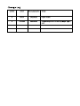
Revision Author Date (yyyy/mm/dd) Change
1 K Detro 2021/02/01 Original release.
2 S Preston 2021/09/13 Updated changes to the UI, including images. Pages 6
and 7.
Change Log
-
 1
1
-
 2
2
-
 3
3
-
 4
4
-
 5
5
-
 6
6
-
 7
7
-
 8
8
-
 9
9
-
 10
10
-
 11
11
-
 12
12
-
 13
13
-
 14
14
-
 15
15
-
 16
16


Monnit Alta 4G LTE Cellular Gateway Guida utente
- Tipo
- Guida utente
in altre lingue
Documenti correlati
Altri documenti
-
ALTA Long Range Wireless Button Press Sensor Manuale utente
-
ZyXEL LTE3202-M430 Manuale utente
-
ZyXEL LTE2566-M634 Guida utente
-
QSG TRB143 Manuale utente
-
ZyXEL LTE4506-M606 Guida utente
-
Moxa OnCell G3101-HSPA Series Manuale utente
-
-
Dell Edge Gateway 3000 Series Guida utente