Monnit ALTA International 3G Cellular Gateway Guida utente
- Tipo
- Guida utente

IMPORTANT!
For best results, please wait to power on your Cellular Gateway until after you have
registered an account on iMonnit and added your gateway and sensors to the online system.
ALTA 3G Cellular Gateway
USER GUIDE
Remote Monitoring for Business

PAGE II
Table of Contents
I. ABOUT THE 3G CELLULAR GATEWAY 1
ALTA 3G CELLULAR GATEWAY FEATURES 1
EXAMPLE APPLICATIONS 1
II. HOW YOUR GATEWAY WORKS 2
III. ORDER OF OPERATIONS 2
IV. GATEWAY REGISTRATION 3
POWERING THE 3G CELLULAR GATEWAY 4
V. INTERNATIONAL 3G CELLULAR GATEWAY SETUP 5
QUICK START - SETUP PROCESS 5
CONFIGURING THE CELLULAR GATEWAY 5
VI. GATEWAY OVERVIEW 7
MENU SYSTEM 7
VII. GATEWAY SECURITY 13
SENSOR COMMUNICATION SECURITY 13
DATA SECURITY ON THE GATEWAY 13
SERVER COMMUNICATION 13
TROUBLESHOOTING 14
SUPPORT 16
WARRANTY INFORMATION 16
CERTIFICATIONS 18
COVERAGE MAPS 23

PAGE 1
I. ABOUT THE 3G CELLULAR GATEWAY
Don't have an existing network connection where you need it most? ALTA Cellular
Gateways allow your Monnit Wireless Sensors to communicate with the iMonnit Online
Wireless Sensor Monitoring and Notification System via cellular transmission. They are
the perfect solution for remote locations, or where an existing Internet connection is not an
option.
The ALTA Cellular Gateways are based on the latest Dual-band CDMA or 3G wireless
protocols and come integrated with Monnit's wireless access point network (WAN) for use
with all Monnit wireless sensors.
The ALTA Cellular Gateway is an advanced all wireless M2M gateway that enables fast
time-to-market solutions for a wide range of M2M and partner applications as well.
Monnit's ALTA Cellular Gateway is specifically designed to respond to the increasing
market need for global technology that accommodates a variety of vertical M2M
application segments and remote wireless sensor management solutions.
ALTA 3G CELLULAR GATEWAY FEATURES
- Wireless range of 1,200+ feet through 12+ walls1
- Frequency Hopping Spread Spectrum (FHSS)
- Improved interference immunity
- Encrypt-RF® Security (Diffie-Hellman Key Exchange + AES-128 CBC for sensor data
messages)
- 50,000 sensor message memory
- Over the air updates (future proof)
- True plug & play, no hassles for Internet configuration set-up
- No PC required for operation
- Low-cost cellular service packages
- Local status LEDs with transmission and online status indicators
- AC power supply
- Optional 24 hour battery backup in event of power outage
- Tri-Band UMTS (GSM/GPRS) (850/1700/1900 MHz)
1. Actual range may vary depending on environment.
EXAMPLE APPLICATIONS
- Remote Location Monitoring
- Shipping and Transportation
- Agricultural Monitoring
- Vacant Property Management
- Vacation Home Property Management
- Construction Site Monitoring
- Data Center Monitoring
* Actual time may vary depending on usage.

PAGE 2
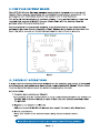
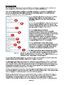
II. HOW YOUR GATEWAY WORKS
Your ALTA 3G Cellular Gateway manages communication between your sensors and
iMonnit. When running, the gateway will periodically transmit data on a heartbeat. The
gateway will store information received from sensors until its next heartbeat.
The ALTA 3G Cellular Gateway is a cellular gateway. It uses cellular towers to relay data
received from sensors to iMonnit. Sensors communicate with the gateway, then the
gateway relays information to the cloud.
For your wireless sensors to work optimally, orient all antennas for your sensor(s) and
gateway(s) the same direction (typically vertical). Sensors must also be at least three feet
away from other sensors and the wireless gateway in order to function properly.
Figure 1
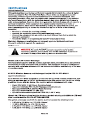
III. ORDER OF OPERATIONS
It is important to understand the order of operations for activating your sensor. If performed
out of sequence, your sensor may have trouble communicating with iMonnit. Please follow
the steps below to make sure you are performing your set-up correctly.
SET-UP STEPS
1. Register your gateway on iMonnit.
Your gateway must be registered first to verify communication between the device and
iMonnit. Any sensors or meters you wish to add onto your network must come after
the gateway.
2. Register your sensor on iMonnit.
Add your sensor to the iMonnit account (see page 3 for step-by-step directions).
3. Mount your sensor.
Place your sensor in the desired location using screws or double-sided
tape.
Note: Each step is covered in more detail in the following sections.

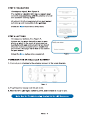
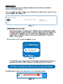
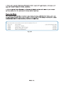
STEP 1: ADD DEVICE
1. Add the gateway on iMonnit.
Add the gateway to your account by choosing Gateways in the main menu.
Navigate to the Add Gateways button.
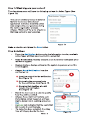
2. Find the device ID. See Figure 3.
The Device ID (ID) and Security Code
(SC) are necessary to add a sensor.
These can both be located on the label
on the side of your device.
3. Adding your device. See Figure 4.
You will need to enter the Device ID
and the Security Code from your
Sensor in the corresponding text boxes.
Use the camera on your smartphone to
scan the QR code on your device. If you
do not have a camera on your phone,
or the system is not accepting the QR
code, you may enter the Device ID
and Security Code manually.
- The Device ID is a unique number
located on each device label.
- Next, you?ll be asked to enter the Security
Code from your device. A security code consists of letters and must be entered in
upper case (no numbers). It can also be found on the barcode label of your device.
When completed, select the Add Device button.
PAGE 3
IV. GATEWAY REGISTRATION
If this is your first time using the iMonnit online portal, you will need to create a new
account. If you have already created an account, start by logging in. For instructions on
how to register and setup your iMonnit account, please consult the iMonnit User Guide.
Desktop Mobile
Figure 3
Figure 4
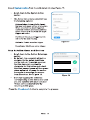
STEP 2: SETUP
Select your use case. See Figure 5.
Set your heartbeat interval and device
name. A heartbeat is how often your
gateway checks in with the iMonnit
server to send sensor readings. 60
minutes is the default setting.
Select the Skip button when completed. Figure 5
Figure 2

PAGE 4
Check your signal. See Figure 6.
The validation checklist will help you ensure your
sensor is communicating with the gateway properly
and you have a strong signal.
Checkpoint 4 will only complete when your sensor
achieves a solid connection to the gateway.
Select the Save button when completed.
STEP 3: VALIDATION
STEP 4: ACTIONS
Choose your actions. See Figure 7.
Actions are the alerts that will be sent to your
phone or email in the event of an emergency.
Low battery life and device inactivity are two of
the most common actions to have enabled on
your device. See page 12 for how to set actions
for your sensor.
Select the Done button when completed.
Figure 6
Figure 7
POWERING THE 3G CELLULAR GATEWAY
1. Connect your antennas to the gateway as seen in the below diagram.
2. Plug the power supply cord into an outlet.
3. After the three LED lights switch to green, your network is ready to use.
Figure 8
Note: See the Troubleshooting Section for the LED Sequence.

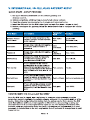
V. INTERNATIONAL 3G CELLULAR GATEWAY SETUP
QUICK START - SETUP PROCESS
1. Set up an iMonnit account and add the cellular gateway and
wireless sensors.
2. Obtain and activate a SIM card on your preferred cellular network.
3. Open the gateway by unscrewing the 4 screws and removing the top.
4. Insert the SIM card into the SIM holder (gold contacts face down - shown at right).
5. Before powering on the gateway, follow the instructions below to configure the cellular
gateway.
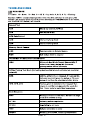
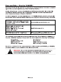
Field Name Description Parameter
Style Example
Cellular Access
Point Name This is a name assigned by the
cellular provider for their specific
m2m network. Apn: name
here; Apn:m2mkit.
telefonica.com;
Username Some data networks will require a
username and sometimes a
password User:
username; User:datauser ;
Password Some data networks will require a
password Pass:
password; Pass: 1234;
DNS setting Assigns the DNS. For Monnit?s
configuration tracking it will
overwrite both DNS fields. Dns: dns; Dns: 8.8.8.8;
Poll interval
This is specific to the cellular
network and is not the same as
Monnit?s internal poll interval for
sending commands to the Control
unit. Default is 45 min; Max is 120
min;
Poll: pollrate; Poll:30;
Host address This is where the gateway should
report to; unless a customer has
Enterprise, it will be Monnit?s host
address. Host: address; Host:sensorsgateway.com;
Host port This is where the gateway should
report to; unless a customer has
Enterprise, it will be Monnit?s host
port. Port: port; Port: 3000;
CONFIGURING THE CELLULAR GATEWAY
Once the SIM card is placed, use a cell phone to compose a text message using the
parameters below to configure the cellular gateway and send it to the mobile number of the
device. Obtain the configuration information from the cellular carrier that provided the SIM
card. Host address and host port are specific to iMonnit if you are planning on using our
cloud services or it is specific to your server if you are not. The example information from
the table below are required for those two fields, but they are pre-programmed so it is not
necessary to include them in the text, only include them if you need to change them to point
to your server.
PAGE 5

PAGE 6
1. Once the text message is composed, send it to the phone number associated with the
SIM card.
2. Attach the provided cellular gateway antennas.
3. Plug in the gateway to power it on.
The gateway will receive the configuration information via text message and store it in
memory. If the setup process is successful the gateway lights will turn green as the
gateway connects. The device will send a response text message to the phone that was
used for configuration. If unsuccessful, the lights will not turn green. If this happens, repeat
the process by unplugging the gateway, sending a new configuration text message to the
device and plugging in the
cellular gateway again.
The format of the text message must have the parameter name followed by a colon
followed by the network- specific data and ended with a semicolon.
One text message can include only one parameter or all parameters. It is recommended to
only send those parameters that need configuring and leave the rest alone. Spaces and
carriage returns are ignored. The parameters are NOT case sensitive.

VI. GATEWAY OVERVIEW
Select Gateways from the main navigation menu on iMonnit to access the
gateway overview page and begin adjusting your device.
MENU SYSTEM
A. History - List of past messages sent by the gateway
B. Actions - List of actions assigned to this gateway
C. Settings - Editable fields for your gateway
D. Sensors - Recent communication from sensors assigned to the gateway
Directly under the tab bar is an overview of your gateway. This allows you to see
the signal strength of the selected device. A colored dot in the left corner of the
icon denotes its status:
- Green indicates the gateway is checking in and is within user-defined safe
parameters.
- Red indicates the gateway has met or exceeded a user-defined threshold
or triggered event.
- Gray indicates no communication with iMonnit, rendering the gateway
inactive.
- Yellow indicates that the gateway communication is out of date, possibly
due to a missed heartbeat check-in.
History View
The History View will be the first page you see upon selecting your gateway.
See Figure 10.
ABCD
Figure 10
The Gateway Messages table lists the date, type, signal, power source, and messages
from the gateway to iMonnit.
PAGE 7
Figure 9

Actions View
Device notifications can be created, deleted, and edited by selecting the
Actions Tab in the tab bar.
You can toggle the Action Trigger on or off by selecting the switch under Current
Action Triggers. See Figure 11.
CREATING AN ACTION
- Actions are triggers or alarms set to notify you when a gateway reading
identifies that immediate attention is needed. Types of actions most used
in relation to the gateway are inactivity alerts and gateway on battery
alerts. Any one of these can be set to send a notification or trigger an
action in the system.
Choose Actions in the main navigation menu.
-
-
- A list of previously created actions will display on the screen. From here,
you have the ability to filter, refresh, and add new actions to the list.
Figure 11
Figure 12
Note: If this is your first time adding an action, the screen will be blank.
From the Actions page, tap Add Action in the left hand corner.
Figure 13
PAGE 8

Step 1: What triggers your action?
The drop-down menu will have the following options for Action Types (See
Figure 14):
Make a selection and press the Save button.
The action creation process is tailored
more to the sensor side of your
application. A Device Inactivity action
was assigned to your gateway during
the device registration process.
Choose "Advanced" for a list of actions
that may pertain to your gateway.
Figure 14
Step 2: Actions
- Press the Add Action button under the information header, available
action types will then be presented in a select list.
- Send Notification: Specify account users to receive notification when
this event triggers.
- System Action: Assign actions for the system to process when this
event triggers.
- Choose Send Notification from the
notification list.
A. Input the subject for the notification.
See Figure 15.
B. Customize the message body
for the notification. See Figure 15.
C. Recipient list identifies who will
receive the notification.
See Figure 16.
- Select the icon next to a user to specify
how they will be notified.
- Choose if you want notifications sent
immediately, when triggered, or if you
want a delay before sending and press
Set.
- A green icon indicates that the users that
will receive the notifications.
- If a delay has been selected, the delay
time will display beside the icon.
Figure 15
Figure 16
A
B
C
PAGE 9

Select System Action from the Add Action list. See Figure 17.
- Scroll down to the System Action
section.
- The Action to be done select list has
the following options:
Acknowledge: Automatically signals
that you have been notified of an action.
When an action has been triggered,
alerts will continue processing until the
action returns to a value that no longer
triggers an action.
Full Reset: Reset your trigger so it is
armed for the next reading.
Activate: Enable an action trigger.
Deactivate: Disable an action trigger.
Figure 17
Step 3: Action Name and Devices
- Scroll down to the Action Gateways
section.
- By default, the sensor(s) will not be
assigned to the action conditions
you?ve just set. To assign a sensor,
find the device(s) you want to
designate for this action and select.
Selected sensor boxes will turn green
when activated. Choose the sensor
box again to unassign the sensor
from the action. See Figure 18.
- Continue toggling the sensor(s)
corresponding to this new action until
you are satisfied with your selection.
These can be adjusted later by
returning to this page.
Press the Check-mark button to complete the process.
Figure 18
PAGE 10

PAGE 11
The 3G Cellular Gateway will receive data from all sensors assigned to the network and
within range, then return this data to the server in a series of heartbeats.
You can access gateway settings by selecting ?Gateways? in the main navigation panel.
Choose the 3G Cellular Gateway from the list of gateways registered to your account.
Select the ?Settings? tab to edit the gateway:
A. The Gateway Name field is where you assign
your gateway a unique title. By default, the
gateway name will be the type followed by the
Device ID.
B. The Heartbeat Minutes configures the interval
that the gateway checks in with the server. The
default is fifteen minutes. So every fifteen minutes
your gateway will report to the server.
C. The Global System for Mobile
Communications utilizes a fifteen digit IMSI
(International Mobile Subscriber Identity) number
as the primary mode to identify the country, mobile
network, and subscriber. It is formatted as
MCC-MNC-MSIN. MCC is the Mobile Country
Code. MNC is the Mobile Network Code attached
to the cellular network. MSIN is a serial number
making the IMSI unique to a subscriber.
D. The ICCID is the nineteen-digit unique
identification number corresponding to the cellular
SIM card. It is possible to change the information
contained on a SIM (including the IMSI), but the
identity of the SIM itself remains the same.
E. IMEI (International Mobile Equipment Identity)
is a number exclusive to your Cellular Gateway to
identify the gateway to the cell tower. The Global System for
Mobile Communications network stores the IMEI numbers in their
database (EIR - Equipment Identity Register).
F. On Aware Messages toggles the gateway to "Wait for Heartbeat" to communicate with
iMonnit when a sensor becomes aware or to "Trigger Heartbeat."
G. Gateway Power Mode grants you the option of choosing Standard, Force Low Power,
or Force High Power. Standard means your gateway will keep lights and operation active
while plugged into an outlet. Force Low Power means your gateway will power down when
not communicating with the server. Force High Power means your gateway will always
keep lights and cellular service active at all times.
H. Reform Network is a command that will trigger the gateway to remove all sensors from
the internal whitelist, and then request a new sensor list from the server. This command will
force all sensors to reinitialize their connection with the gateway.
Reforming the network cleans up communication when multiple networks are in range of
each other so they are all in sync. This is especially useful if you must move sensors to a
new network, and would like to clear these sensors from the gateway?s internal list.
Reforming the network will place a new list of sensors that will continue to exchange data.
Figure 19
A
B
C
D
E
F
G
HIJ
Settings View

I. Picking the Update Gateway Firmware button signals the gateway to download and
apply the latest firmware version available.
J. Choosing the Reset Gateway to Factory Defaults button will erase all your unique
settings and return the gateway to factory default settings.
Sensors View
The sensors view lists the sensors on your account along with their ID, Name, and Last
Communication Date. This is a good way to keep track of how many sensors are on your
account and whether there are any that are not reporting.
PAGE 12
Figure 20

VII. GATEWAY SECURITY
DATA SECURITY ON THE GATEWAY
SENSOR COMMUNICATION SECURITY
The ALTA 3G Cellular Gateway has been designed and built to securely manage data from
sensors monitoring your environment and equipment. Hacking from botnets are in the
headlines, Monnit Corporation has taken extreme measures to ensure your data security is
handled with the utmost care and attention to detail. The same methods utilized by financial
institutions to transmit data are also used in Monnit security infrastructure. Security features
of the gateway include tamper proof network interfaces, data encryption, and bank-grade
security.
SERVER COMMUNICATION SECURITY
Monnit?s proprietary sensor protocol uses low transmit power and specialized radio
equipment to transmit application data. Wireless devices listening on open communication
protocols cannot eavesdrop on sensors. Packet level encryption and verification is key to
ensuring traffic isn?t altered between sensors and gateways. Paired with best-in-class
range and power consumption protocol, all data is transmitted securely from your devices.
Thereby ensuring a smooth, worry-free, experience.
Monnit sensor to gateway secure wireless tunnel is generated using ECDH-256 (Elliptic
Curve Diffie-Hellman) public key exchange to generate a unique symmetric key between
each pair of devices. Sensors and gateways use this link specific key to process packet
level data with hardware accelerated 128-bit AES encryption which minimizes power
consumption to provide industry best battery life. Thanks to this combination, Monnit
proudly offers robust bank-grade security at every level.
The ALTA 3G Gateway is designed to prevent prying eyes from accessing the data that is
stored on the sensors. The ALTA 3G Cellular Gateway does not run on an off the shelf
multi-function OS (operating system). Instead it runs a purpose specific real-time
embedded state machine that cannot be hacked to run malicious processes. There are
also no active interface listeners that can be used to gain access to the device over the
network. The fortified gateway secures your data from attackers and secures the gateway
from becoming a relay for malicious programs.
Communication between your ALTA 3G Cellular Gateway and iMonnit is secured by packet
level encryption. Similar to the security between the sensors and gateway, the gateway and
server also establish a unique key using ECDH-256 for encrypting data. The packet level
data is encrypted end to end removing additional requirements to configure specialized
cellular VPN?s. The gateway can still operate within a VPN if it is present. Because all traffic
is initiated from the gateway there is no special IP configuration needed for the gateway
allowing it to operate with any 3G enabled SIM provider.
PAGE 13

TROUBLESHOOTING
Internal Test
AAA Check low level init, APN init
AAR APN Failed to talk
APN Com Passed
AAG Internal memory check
ARG Internal memory failed
Memory Check Passed
AGG Communication to Cellular Module
RGG Cell module failed to respond
Cell Module Communication Established
GGG 2 Seconds Boot Mode Passed Successfully. If
button is held down during this 2 seconds,
gateway enters Offline Test mode
Offline Factory Test Mode (for testing devices that are not activated on a cellular
network)
RRR Until the utility button is released. If it entered this
state and you didn't press the button or if it never
leaves all red then it's a hardware button failure.
GFR, GFR, GFR Flashes green to indicate button released then
returns to red. Not recommended for use in the
field. Power cycle to restart boot sequences.
Boot Sequence
ROO Waiting to connect to cell tower. No tower in range,
check that antenna is snug.
RF1OO Obtaining cellular registration
RF5OO Negotiating to cell tower
GOO Cellular connection to tower
GF2OO Obtaining IP Address, initializing data session
LED SEQUENCE
KEY:
A = Amber G = Green R = Red O = Off X = Any Color A, G, R, O Fx = Flashing
Example: GG5G - Communicating to the server. The first LED (top) is solid green, the
second LED (middle) blinks for half a second indicating the communication to the server,
and the third LED (bottom) will be solid.
PAGE 14

GF1OO DNS Resolving
GRF5O Communicating to server
GGRF5 Network Reforming
GGG Run Mode
Run Mode
GGG All systems online and previous server
communication successful
GF5XX AGPS/GPS being acquired
GRG All systems online and previous server
communication failed.
GF5RG Last Server communication failed and cellular data
link is attempting to reestablish.
RRG Last Server communication failed and cellular data
link was not active.
RGG Cellular service unavailable. No communication.
GGRF5 Network reforming
GGF5G Communicating to server, previous server
communication successful
GGGF5 Communication with sensor
RF1XG Negotiating to cell tower
GF2XG Obtaining IP Address, initializing data session
GF1XG DNS Resolving
Code Error
RF5 Two flashes then off for 2 seconds, repeat
SMS Message Lights
FGFGFG 20 Seconds - On reception of successful SMS
configuration message
XXX No reaction on no reception of valid text
Error Codes
FRFRFR 1 second - Cell Modem failed to start
2 seconds - Failed to extract identifiers
10 seconds - SIM locked or SIM failure, Network
locked, Illegal MS or ME, AKA not configured not
set up correctly or bad geographical location.
PAGE 15

SUPPORT
WARRANTY INFORMATION
(a) Monnit warrants that Monnit-branded products (Product) will be free from defects in
materials and workmanship for a period of one (1) year from the date of delivery with
respect to hardware and will materially conform to their published specifications for a period
of one (1) year with respect to software. Monnit may resell sensors manufactured by other
entities and are subject to their individual warranties; Monnit will not enhance or extend
those warranties. Monnit does not warrant that the software or any portion thereof is error
free. Monnit will have no warranty obligation with respect to Products subjected to abuse,
misuse, negligence or accident. If any software or firmware incorporated in any Product
fails to conform to the warranty set forth in this section, Monnit shall provide a bug fix or
software patch correcting such non-conformance within a reasonable period after Monnit
receives from customer (i) notice of such non-conformance, and (ii) sufficient information
regarding such non-conformance so as to permit Monnit to create such bug fix or software
patch. If any hardware component of any Product fails to conform to the warranty in this
section, Monnit shall, at its option, refund the purchase price less any discounts, or repair
or replace nonconforming Products with conforming Products, or Products having
substantially identical form, fit, and function and deliver the repaired or replacement
Product to a carrier for land shipment to customer within a reasonable period after Monnit
receives from customer (i) notice of such non-conformance, and (ii) the non-conforming
Product provided; however, if, in its opinion, Monnit cannot repair or replace on
commercially reasonable terms it may choose to refund the purchase price. Repair parts
and replacement Products may be reconditioned or new. All replacement Products and
parts become the property of Monnit. Repaired or replacement Products shall be subject to
the warranty, if any remains, originally applicable to the Product repaired or replaced.
Customer must obtain from Monnit a Return Material Authorization Number (RMA) prior to
returning any Products to Monnit. Products returned under this warranty must be
unmodified.
Customer may return all Products for repair or replacement due to defects in original
materials and workmanship if Monnit is notified within one year of customer?s receipt of the
Product. Monnit reserves the right to repair or replace Products at its own and complete
discretion. Customer must obtain from Monnit a Return Material Authorization Number
(RMA) prior to returning any Products to Monnit. Products returned under this Warranty
must be unmodified and in original packaging. Monnit reserves the right to refuse warranty
repairs or replacements for any Products that are damaged or not in original form. For
Products outside the one year warranty period repair services are available at Monnit at
standard labor rates for a period of one year from the customer?s original date of receipt.
(b) As a condition to Monnit?s obligations under the immediately preceding paragraphs,
customer shall return Products to be examined and replaced to Monnit?s facilities, in
shipping cartons which clearly display a valid RMA number provided by Monnit. Customer
acknowledges that replacement Products may be repaired, refurbished or tested and found
to be complying. Customer shall bear the risk of loss for such return shipment and shall
bear all shipping costs. Monnit shall deliver replacements for Products determined by
Monnit to be properly returned.
PAGE 16
For technical support and troubleshooting tips please visit our support library online at
monnit.com/support/. If you are unable to solve your issue using our online support, email
Monnit support at [email protected] with your contact information and a description of
the problem, and a support representative will call you within one business day.
For error reporting, please email a full description of the error to [email protected].

(c) Monnit?s sole obligation under the warranty described or set forth here shall be to repair
or replace non-conforming Products as set forth in the immediately preceding paragraph, or
to refund the documented purchase price for non-conforming Products to customer.
Monnit?s warranty obligations shall run solely to customer, and Monnit shall have no
obligation to customers of customer or other users of the products.
Limitation of Warranty and Remedies.
THE WARRANTY SET FORTH HEREIN IS THE ONLY WARRANTY APPLICABLE TO
PRODUCTS PURCHASED BY CUSTOMER. ALL OTHER WARRANTIES, EXPRESS OR
IMPLIED, INCLUDING BUT NOT LIMITED TO THE IMPLIED WARRANTIES OF
MERCHANTABILITY AND FITNESS FOR A PARTICULAR PURPOSE ARE EXPRESSLY
DISCLAIMED. MONNIT?S LIABILITY WHETHER IN CONTRACT, IN TORT, UNDER ANY
WARRANTY, IN NEGLIGENCE OR OTHERWISE SHALL NOT EXCEED THE PURCHASE
PRICE PAID BY CUSTOMER FOR THE PRODUCT. UNDER NO CIRCUMSTANCES
SHALL MONNIT BE LIABLE FOR SPECIAL, INDIRECT OR CONSEQUENTIAL
DAMAGES. THE PRICE STATED FOR THE PRODUCTS IS A CONSIDERATION IN
LIMITING MONNIT?S LIABILITY. NO ACTION, REGARDLESS OF FORM, ARISING OUT
OF THIS AGREEMENT MAY BE BROUGHT BY CUSTOMER MORE THAN ONE YEAR
AFTER THE CAUSE OF ACTION HAS ACCRUED.
IN ADDITION TO THE WARRANTIES DISCLAIMED ABOVE, MONNIT SPECIFICALLY
DISCLAIMS ANY AND ALL LIABILITY AND WARRANTIES, IMPLIED OR EXPRESSED,
FOR USES REQUIRING FAIL-SAFE PERFORMANCE IN WHICH FAILURE OF A
PRODUCT COULD LEAD TO DEATH, SERIOUS PERSONAL INJURY, OR SEVERE
PHYSICAL OR ENVIRONMENTAL DAMAGE SUCH AS, BUT NOT LIMITED TO, LIFE
SUPPORT OR MEDICAL DEVICES OR NUCLEAR APPLICATIONS. PRODUCTS ARE
NOT DESIGNED FOR AND SHOULD NOT BE USED IN ANY OF THESE
APPLICATIONS.
PAGE 17

CERTIFICATIONS
United States FCC
This equipment has been tested and found to comply with the limits for a Class B digital
devices, pursuant to Part 15 of the FCC Rules. These limits are designed to provide
reasonable protection against harmful interference in a residential installation. This
equipment generates, uses, and can radiate radio frequency energy and, if not installed
and used in accordance with the instruction manual, may cause harmful interference to
radio communications. However, there is no guarantee that interference will not occur in a
particular installation. If this equipment does cause harmful interference to radio or
television reception, which can be determined by turning the equipment off and on, the
user is encouraged to try to correct the interference by one of more of the following
measures:
- Reorient or relocate the receiving antenna.
- Increase the separation between the equipment and receiver
- Connect the equipment into an outlet on a circuit different from that to which the
receiver is connected.
- Consult the dealer or an experienced radio/TV technician for help.
Warning: Changes or modifications not expressly approved by Monnit could void
the user?s authority to operate the equipment.
RF Exposure
Monnit and ALTA Cellular Gateways:
This equipment complies with the radiation exposure limits prescribed for an uncontrolled
environment for fixed and mobile use conditions. This equipment should be installed and
operated with a minimum distance of 23 cm between the radiator and the body of the user
or nearby persons.
PAGE 18
All ALTA Wireless Sensors and Gateways Contain FCC ID: ZTL-G2SC1.
Approved Antennas
ALTA devices have been designed to operate with an approved antenna listed below, and
having a maximum gain of 14 dBi. Antennas having a gain greater than 14 dBi are strictly
prohibited for use with this device. The required antenna impedance is 50 ohms.
- Xianzi XQZ-900E (5 dBi Dipole Omnidirectional)
- HyperLink HG908U-PRO (8 dBi Fiberglass Omnidirectional)
- HyperLink HG8909P (9 dBd Flat Panel Antenna)
- HyperLink HG914YE-NF (14 dBd Yagi)
- Specialized Manufacturing MC-ANT-20/4.0C (1 dBi 4? whip)
Monnit 4G LTE International Cellular Gateway models starting with MNG2-9-LTE-CCE
also contain module: FCC ID: XPY2AGQN4NNN
The system antenna(s) used with the device must not exceed the following levels:
- 3.67 dBi in 700 MHz, i.e. LTE FDD-12 band
- 10 dBi in 850 MHz, i.e. LTE FDD-5 band
- 6.74 dBi in 1700 MHz, i.e. LTE FDD-4 band
- 7.12 dBi in 1900 MHz, i.e. LTE FDD-2 band
WARNING: To satisfy FCC RF exposure requirements for mobile
transmitting devices, the antenna used for this transmitter must not be
co-located in conjunction with any antenna or transmitter.
La pagina si sta caricando...
La pagina si sta caricando...
La pagina si sta caricando...
-
 1
1
-
 2
2
-
 3
3
-
 4
4
-
 5
5
-
 6
6
-
 7
7
-
 8
8
-
 9
9
-
 10
10
-
 11
11
-
 12
12
-
 13
13
-
 14
14
-
 15
15
-
 16
16
-
 17
17
-
 18
18
-
 19
19
-
 20
20
-
 21
21
-
 22
22
-
 23
23


Monnit ALTA International 3G Cellular Gateway Guida utente
- Tipo
- Guida utente
in altre lingue
Documenti correlati
Altri documenti
-
ALTA Long Range Wireless Button Press Sensor Manuale utente
-
Moxa OnCell G3101/G3201 Series Manuale utente
-
-
ZyXEL LTE3202-M430 Manuale utente
-
Pepwave Surf-SOHO Manuale utente
-
Zoom 1098 Manuale utente
-
Schneider Electric Enerlin’X IFE Ethernet Interface Guida utente