
VQT5K49
CH0314TY0 -FJ
Operating Instructions
Bedienungsanleitung
Mode d’emploi
Instrucciones de funcionamiento
Istruzioni per l’uso
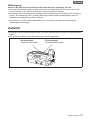
Interface Unit/Video-Interface
Unité d’interface A/V/Unidad interface
Interface Unit
Model No.
DMW-YAGHE
Please read these instructions carefully before using this product, and save
this manual for future use.
Bitte lesen Sie diese Anleitung vor der Inbetriebnahme dieses Produkts
aufmerksam durch, und bewahren Sie dieses Handbuch für spätere
Bezugnahme griffbereit auf.
Veuillez lire attentivement les présentes instructions avant d’utiliser ce
produit, et conserver ce manuel pour utilisation ultérieure.
Lea cuidadosamente estas instrucciones antes de usar este producto, y
guarde este manual para usarlo en el futuro.
Leggere attentamente queste istruzioni prima di utilizzare il presente
prodotto, e conservare questo manuale per usi futuri.
E

2
VQT5K49 (ENG)
ENGLISH
Read this first!
indicates safety information.
WARNING:
• To reduce the risk of fire, do not expose this equipment to rain or moisture.
• To reduce the risk of fire, keep this equipment away from all liquids. Use
and store only in locations which are not exposed to the risk of dripping
or splashing liquids, and do not place any liquid containers on top of the
equipment.
WARNING:
Always keep accessory (terminal cap) out of the reach of babies and small
children.
CAUTION:
Do not remove panel covers by unscrewing.
No user serviceable parts inside.
Refer servicing to qualified service personnel.
CAUTION:
In order to maintain adequate ventilation, do not install or place this unit in a
bookcase, built-in cabinet or any other confined space. To prevent risk of fire
hazard due to overheating, ensure that curtains and any other materials do
not obstruct the ventilation.
CAUTION:
To reduce the risk of fire and annoying interference, use the recommended
accessories only.
CAUTION:
Do not leave the unit in direct contact with the skin for long periods of time
when in use.
Low temperature burn injuries may be suffered if the high temperature parts of
this unit are in direct contact with the skin for long periods of time.
When using the equipment for long periods of time, make use of the tripod.

(ENG) VQT5K49
3
ENGLISH
Read this first! (continued)
The rating plate is on the underside of the unit.
EEE Yönetmeliğine Uygundur.
EEE Complies with Directive of Turkey.
CAUTION:
Do not lift the unit or the camera with a tripod attached.
The additional weight on the unit from the attached tripod may damage the
connection between the unit and the camera, and may result in injuries.
When a tripod is attached, always carry the equipment by the tripod.
indicates safety information.

4
VQT5K49 (ENG)
ENGLISH
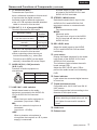
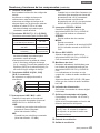
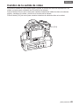
The unit is exclusively for Panasonic DMC-GH4 digital camera.
Mounting the unit to a digital camera allows you to output 4K, 3G-SDI, and HD-SDI compatible
video from the SDI terminal and perform video production with higher-quality video.
Two-channel audio input (XLR) is supported with audio level meters available.
You can also input an external timecode to be used as a reference signal.
When the unit is mounted on a digital camera, the electronic sound and electronic shutter
sound of the digital camera are disabled.
Contents
Read this first! ...............................................2
Accessories ...................................................5
Names and Functions of Components ........6
Mounting to the Digital Camera ...................8
Switching the Video Output ..........................9
Additional Menus .........................................10
Specifications ..............................................12
Handling the unit
The unit is not splash proof or dust proof.
Be careful not to allow sand, dust, or water to adhere or enter into the terminal area, digital
camera, or this unit when attaching or removing this unit.
This unit is not waterproof, so it cannot be used underwater.
Do not subject the unit to strong shocks or vibration. Doing so may result in malfunction or
damage.
When the unit is mounted on the digital camera, do not use the shoulder strap supplied with the
digital camera. Always hold both the digital camera and the unit while carrying.
Keep the unit away from insecticide sprays and other volatile substances.
If the unit is exposed to these sprays or substances, its external case may deteriorate and/or its
paint may come off.
Do not leave the unit in contact with any items made of rubber or PVC for prolonged periods of
time.
Under no circumstances should the unit be used or stored in any of the following locations
since doing so may cause trouble in operation or malfunctioning:
• In direct sunlight or on a beach in summer
• In locations with high temperatures and humidity
levels or where changes in temperature and
humidity are acute
• Where there is fire
• Near heaters, air conditioners or
humidifiers
• Where there is vibration
• Inside a vehicle
Please also read the operating instructions of your digital camera.
Panasonic will not be liable for any direct or indirect damages or losses resulting from
operation or malfunction of this product.
The design and specifications found in this document are subject to change without notice
and may differ from the actual product.
If the unit’s fan stops due to a malfunction or error and you continue to operate the unit, video
output may not be performed properly.

(ENG) VQT5K49
5
ENGLISH
Cleaning
When cleaning, wipe the unit with a dry soft cloth.
When the unit is soiled badly, it can be cleaned by wiping the dirt off with a well-wrung wet
cloth, and then with a dry cloth.
Do not use solvents such as benzine, thinner, alcohol, kitchen detergents, etc., to clean the
unit, since they may deteriorate the external case or the coating may come off.
When using a chemical cloth, be sure to follow the accompanying instructions.
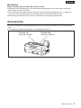
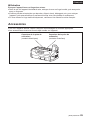
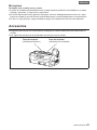
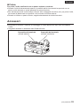
Accessories
Be sure to dispose of the packaging materials in an appropriate manner after unpacking the
unit.
The following supplied accessories come attached to the unit.
Terminal cap
(electrical contacts)
Terminal cap
(interface contacts)

6
VQT5K49 (ENG)
ENGLISH
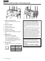
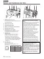
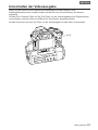
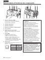
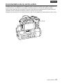
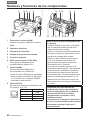
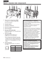
Names and Functions of Components
4 18 2 3 4 5 14141
11
8
109
1812131216 157 19617
1 HDMI connection terminal
Connects to the digital camera’s HDMI
connector.
2 Electrical contacts
3 Interface contacts
4 Camera attachment pins
5 Attachment screw
6 Screw hole (1/4-20 UNC)
Attaches to PL lens compatibility adapters,
etc.
7 HDMI terminal
HDMI Type A output terminal.
(VIERA Link is not supported.)
Use a high-speed double-shielded
4K-compatible HDMI cable (up to 2 m)
that is marked with the HDMI logo when
connecting to this terminal.
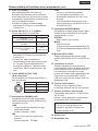
8 DC IN terminal
Connects to the DC power supply (battery:
12 V DC).
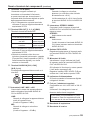
1
2
3
4
Pin no. Signal
1 GND
2, 3 —
4 12 V
CASE Frame GND
Notes on DC power supply (battery)
Verify that the output voltage matches the
unit’s voltage rating before connection.
Use a rated output current that is equal
to or higher than the unit’s input current
rating.
Use a shielded cable that is less than 2 m
in length for the DC cable connecting the
unit to the DC power supply (battery).
An inrush current is generated when the
digital camera is turned on. An insufficient
power supply capacity when the power is
turned on may result in malfunction. We
recommend using a DC power supply
(battery) that can provide at least twice the
power consumption value of the unit.
Verify the pin positions of the output
connector of the DC power supply
(battery) and the unit’s DC IN terminal,
and be sure to connect with the correct
polarities.
Connecting +12 V power to the GND
terminal may result in fire or malfunction.

(ENG) VQT5K49
7
ENGLISH
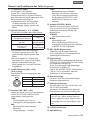
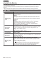
9 TC IN terminal (BNC)
Timecodes are input here.
Input a reference timecode to this terminal
to synchronise the digital camera’s
timecode to that of external equipment.
Use a 5C-FB equivalent double-shielded
cable to connect to this terminal.
10 SDI OUT [1, 2, 3, 4] terminals (BNC)
Terminals reserved for SDI output.
Resolution setting
Output
terminal
C4K, 4K
<1.5G-SDI Square Division>
1 to 4
FHD (1080/59.94p, 1080/50p)
<3G-SDI>
1, 2
(same signal)
FHD (Other than the above), HD
<1.5G-SDI>
1 to 4
(same signal)
Use a 5C-FB equivalent double-shielded
cable to connect to this terminal.
When outputting videos that do not
include timecodes (e.g., when [Rec
Format] is set to [MP4] on the digital
camera), a timecode will not be output.
11 AUDIO IN [CH1, CH2] terminals
(XLR, 3-pin)
Connects to audio equipment or
microphones.
PUSH
1
3
2
Pin no. Signal
1 GND
2 AUDIO IN (H)
3 AUDIO IN (C)
12 LINE / MIC / +48V switches
Switch these based on the audio
equipment connected to the AUDIO IN
CH1 or AUDIO IN CH2 terminal.
LINE:
When line input audio equipment is
connected. (Input level: 0 dBu)
MIC:
When an external microphone is
connected.
(Input level:
-
50 dBu)
+48V:
When a phantom microphone (a
microphone that requires a +48 V power
supply) is connected.
A power supply of +48 V will be
provided to the AUDIO IN CH1 and
AUDIO IN CH2 terminals.
13 STEREO / MONO switch
Switches the audio that is input to the
AUDIO IN CH1 and AUDIO IN CH2
terminals to stereo or monaural audio.
STEREO:
Two-channel stereo audio.
MONO:
Monaural audio.
The audio that is input to the AUDIO
IN CH1 terminal will also be input to
AUDIO IN CH2.
14 REC LEVEL dials
Adjust the audio inputs to the AUDIO
IN CH1 and AUDIO IN CH2 terminals
individually.
15 Level meters
Display individual indicators for the audio
input levels of the AUDIO IN CH1 and
AUDIO IN CH2 terminals.
The indicators light red when the audio
levels exceed 0 dB.
Adjust the REC LEVEL dials (
14) to
prevent the audio levels from exceeding
0 dB.
16 Power indicator
Lights when the connected digital camera
is turned on.
17 Tripod attachment holes
Compatible with 1/4-20 UNC and 3/8-16
UNC screws.
Use the appropriate hole according to the
diameter of the tripod screw.
The holes have a depth of 5.5 mm.
When attaching a tripod to the unit, do
not tighten the screw with excessive
force.
18 Intake vent
19 Exhaust vent
Names and Functions of Components (continued)

8
VQT5K49 (ENG)
ENGLISH
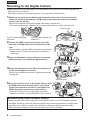
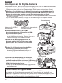
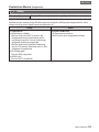
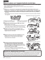
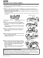
Mounting to the Digital Camera
Make sure that a DC power supply is not connected to the unit’s DC IN terminal and that the
digital camera is turned off.
(Mounting or dismounting while the power is on may result in malfunction.)
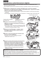
1 Remove the cover for the battery grip connector and cover for the interface unit
connector on the digital camera, and remove the electrical contact and interface
contact caps on the unit.
Store the connector covers and contact caps safely to avoid loss.
To protect the terminals, reattach the covers and caps after you finish using the unit.
Cover for the battery grip
connector
Cover for the interface unit
connector
Terminal caps
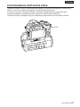
2 Loosen the HDMI connection terminal screw (A),
and slide the HDMI connection terminal out to the
side.
Do not twist or pull the HDMI connection terminal with
excessive force. Doing so may result in malfunction
or damage.
3 Align the attachment screw, contacts, and camera
attachment pins, and attach the digital camera.
4 Rotate the attachment screw (B) in the direction of
the arrow and tighten it securely.
Verify that the attachment screw is tightened securely
during use.
5 Open the terminal cover on the digital camera, slide
the HDMI connection terminal on the unit inward
(toward the camera) to connect it, and tighten the
HDMI connection terminal screw (A) securely.
Open the terminal cover on the digital camera 90
degrees, and store it in the HDMI connection terminal.
(B)
Terminal cover
90°
(A)
Dismounting from the digital camera
Make sure that a DC power supply is not connected to the unit’s DC IN terminal and that
the digital camera is turned off, and then perform the mounting procedure in reverse order
(disconnect the HDMI connection terminal before rotating the attachment screw (B)).
Performing the procedure in the incorrect order may result in damage.

(ENG) VQT5K49
9
ENGLISH
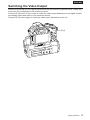
Switching the Video Output
When you mount the unit on a digital camera and set the camera to playback mode, videos and
menus will not be displayed in the camera’s monitor.
Press the [Fn3] button in such cases to switch the video output destination to the digital camera
and display videos and menus in the camera’s monitor.
Press the [Fn3] button again to switch the video output destination to the unit.
[Fn3]

10
VQT5K49 (ENG)
ENGLISH
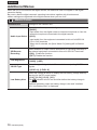
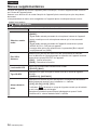
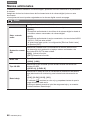
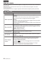
Additional Menus
When the unit is mounted on the digital camera, an additional menu will appear in the digital
camera’s display.
Be sure to read the digital camera’s operating instructions together with this document.
Menu settings are registered to the digital camera when you turn it off.
Motion Picture
Interface Unit Settings for the interface unit
Audio Input Select
Select the audio to input to the digital camera.
[BODY]:
Input audio from the digital camera’s internal microphone or from the
external microphone connected to the digital camera.
[XLR]:
Input audio from the equipment connected to this unit’s AUDIO IN
[CH1, CH2] terminals.
When this is selected, the [Lens Noise Cut] setting will be fixed at
[OFF].
SDI Remote
Recording
Select whether to output control information for recording start/stop to
the external equipment connected to this unit’s SDI OUT terminals.
[ON]: Enable the function.
[OFF]: Disable the function.
LED Brightness
Specify the brightness of the level meters.
[HIGH], [LOW]
3G-SDI Type
Select the type of signal that will be used when outputting 3G-SDI
signals.
[LEVEL A], [LEVEL B]
Low Battery Alert
Select the voltage at which to display the low battery (voltage decline)
warning for the DC power battery.
[11V], [12.5V], [13.5V], [15V]
The
indicator will turn red and blink before the battery charge is
empty.
Replace the battery when the battery charge is low and “Interface
Unit: Low Battery Alert” is displayed.

(ENG) VQT5K49
11
ENGLISH
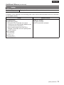
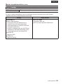
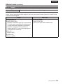
Setup
Version Disp. Display the firmware version of the unit that is added.
In addition, some settings in the following menu items will be restricted when the unit is mounted
on the digital camera.
Setup Motion Picture
TV Connection
HDMI Mode (Play):
• When [AUTO] is selected, the output
resolution is set automatically based on the
recorded format (resolution).
• When a setting other than [AUTO] is
selected, timecodes are not superimposed
on SDI outputs.
3D Playback:
Fixed at [2D].
VIERA Link:
Fixed at [OFF].
HDMI Rec Output
4K Down Convert:
[AUTO] cannot be selected.
Additional Menus (continued)

12
VQT5K49 (ENG)
ENGLISH
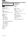
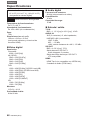
Power source:
DC 12 V (11 V – 17 V), 1.4 A (DC 12 V)
(including digital camera)
indicates safety information.
Operating temperature:
0 °C to 40 °C
Operating humidity:
10% to 80% (non-condensing)
Weight:
750 g
Dimensions (WHD):
160 mm64 mm91 mm
(excluding protrusions and HDMI connection
terminal)
Digital video
Resolution:
Cinema4K:
40962160 [24p]
4K (QFHD):
38402160 [29.97p]
38402160 [25p]
38402160 [24p]
38402160 [23.98p]
FHD:
19201080 [59.94p] (3G-SDI Level-A/B)
19201080 [50p] (3G-SDI Level-A/B)
19201080 [59.94i]
19201080 [50i]
19201080 [24PsF]
19201080 [23.98PsF]
HD:
1280720 [59.94p]
1280720 [50p]
Sampling:
Y:Cb:Cr = 4:2:2
Bit depth:
8 bit / 10 bit
Digital audio
Sampling frequency:
48 kHz (video sync)
Quantization:
16 bit
Headroom:
12 dB
Input / output
TC IN:
BNC1, 1.0 V [p-p] to 4.0 V [p-p], 10 kΩ
AUDIO IN:
XLR (3-pin)2, high impedance,
LINE/MIC/+48V (switchable)
LINE : 0 dBu
MIC :
-
50 dBu
+48V : +48 V phantom supported,
-
50 dBu
SDI OUT:
BNC4, 0.8 V [p-p], 75 Ω,
Audio output: SDI OUT 1
Embedded audio: 2 channel
Timecode output: SDI OUT 1
Embedded LTC
HDMI:
HDMI Type A (VIERA Link not supported),
2-channel audio (linear PCM)
Specifications

(ENG) VQT5K49
13
ENGLISH
Information on Disposal for Users of Waste Electrical & Electronic
Equipment (private households)
This symbol on the products and/or accompanying documents means
that used electrical and electronic products should not be mixed with
general household waste.
For proper treatment, recovery and recycling, please take these
products to designated collection points, where they will be accepted
on a free of charge basis. Alternatively, in some countries you may be
able to return your products to your local retailer upon the purchase of
an equivalent new product.
Disposing of this product correctly will help to save valuable resources and prevent
any potential negative effects on human health and the environment which could
otherwise arise from inappropriate waste handling.
Please contact your local authority for further details of your nearest designated
collection point.
Penalties may be applicable for incorrect disposal of this waste, in accordance with
national legislation.
For business users in the European Union
If you wish to discard electrical and electronic equipment, please contact your dealer
or supplier for further information.
Information on Disposal in other Countries outside the European
Union
This symbol is only valid in the European Union.
If you wish to discard this product, please contact your local authorities or dealer and
ask for the correct method of disposal.

14
VQT5K49 (GER)
DEUTSCH
Bitte lesen Sie zuerst diesen Hinweis!
ist die Sicherheitsinformation.
WARNUNG:
• Setzen Sie dieses Gerät zur Reduzierung der Brandgefahr weder Nässe
noch Feuchtigkeit aus.
• Um die Brandgefahr zu reduzieren, muss dieses Gerät von allen
Flüssigkeiten ferngehalten werden. Vermeiden sie Gebrauch und
Lagerung des Gerätes an Orten, an denen die Gefahr besteht, dass
es mit Flüssigkeiten betropft oder bespritzt wird, und stellen sie keine
Flüssigkeitsbehälter auf das Gerät.
WARNUNG:
Bewahren Sie Zubehörteile (Buchsenkappe) stets außerhalb der Reichweite
von Säuglingen und Kleinkindern auf.
VORSICHT:
Öffnen Sie nicht das Gerät durch Abschrauben von Gehäuseteilen.
Im Geräteinneren befinden sich keine Teile, die vom Benutzer gewartet
werden können.
Wartungs- und Reparaturarbeiten grundsätzlich autorisiertem
Kundendienstpersonal überlassen.
VORSICHT:
Um eine ausreichende Belüftung zu gewährleisten, dieses Gerät nicht in
einem Bücherregal, Einbauschrank oder an einem anderen engen Platz
aufstellen.
Stellen Sie sicher, dass die Ventilationsöffnungen im Gehäuse nicht durch
Vorhänge oder andere Materialien blockiert werden; anderenfalls besteht die
Gefahr von Bränden aufgrund von Überhitzung.
VORSICHT:
Verwenden Sie nur das empfohlene Zubehör, um die Gefahr von Bränden
sowie Störungen zu reduzieren.

(GER) VQT5K49
15
DEUTSCH
VORSICHT:
Die Einheit bei längerem Gebrauch nicht direkt mit der Haut berühren.
Verbrennungen durch niedrige Temperaturen sind möglich, wenn die heißen
Komponenten dieser Einheit für lange Zeit in direktem Hautkontakt stehen.
Bei längerer Verwendung der Ausrüstung das Stativ einsetzen.
Bitte lesen Sie zuerst diesen Hinweis! (fortgesetzt)
Das Typenschild befindet sich auf der Unterseite des Geräts.
VORSICHT:
Heben Sie das Gerät oder die Kamera nicht mit einem daran befestigtem
Stativ an.
Das zusätzliche Gewicht des befestigten Stativs am Gerät könnte die
Verbindung zwischen dem Gerät und der Kamera beschädigen und
Verletzungen verursachen.
Tragen Sie die Ausrüstung bei angebrachtem Stativ immer am Stativ selbst.
ist die Sicherheitsinformation.

16
VQT5K49 (GER)
DEUTSCH
Dieses Gerät ist ausschließlich für die Digital-Kamera von Panasonic DMC-GH4 bestimmt.
Durch Anbringen dieses Geräts an einer Digital-Kamera können über die SDI-Buchse mit 4K,
3G-SDI und HD-SDI kompatible Videos ausgegeben werden. Zudem lassen sich Videos mit
einer höheren Bildqualität aufnehmen.
Zwei-Kanal-Audioeingänge (XLR) werden mit verfügbaren Audiopegelanzeigen unterstützt.
Zudem kann ein externer Zeitcode als Referenzsignal eingegeben werden.
Wenn dieses Gerät an einer Digital-Kamera befestigt ist, werden elektronische
Betriebsgeräusche und der elektronische Auslöseton der Digital-Kamera deaktiviert.
Inhalt
Bitte lesen Sie zuerst diesen Hinweis! ......14
Zubehör ........................................................17
Namen und Funktionen der Teile ...............18
Anbringen an die Digital-Kamera ...............20
Umschalten der Videoausgabe ..................21
Zusätzliche Menüs.......................................22
Technische Daten ........................................24
Handhabung des Geräts
Dieses Gerät ist weder spritzwasserfest noch staubdicht.
Achten Sie darauf, dass weder Sand, Staub noch Wasser in den Bereich der Kontakte, die
Digital-Kamera oder dieses Gerät eindringen bzw. in diesen anhaften, wenn Sie dieses Gerät
anbringen oder abnehmen.
Dieses Gerät ist nicht wasserdicht und darf deshalb nicht unter Wasser benutzt werden.
Setzen Sie das Gerät keinen starken Erschütterungen oder Stößen aus. Dadurch kann es zu
Funktionsstörungen und Defekten kommen.
Wenn dieses Gerät an der Digital-Kamera befestigt ist, verwenden Sie nicht den mit dieser
Digital-Kamera mitgelieferten Schultergurt. Halten Sie beim Transport sowohl die Digital-
Kamera als auch das Gerät fest.
Halten Sie das Gerät von Insektensprays und anderen flüchtigen Substanzen fern.
Wird das Gerät solchen Sprays oder Substanzen ausgesetzt, kann seine äußere Hülle
beschädigt werden und/oder seine Farbe abblättern.
Bringen Sie das Gerät nicht über längere Zeiträume mit Gegenständen aus Gummi oder PVC
in Kontakt.
Keinesfalls sollte das Gerät unter den folgenden Bedingungen aufbewahrt werden, da dies zu
Defekten oder Funktionsstörungen führen kann:
• In direktem Sonnenlicht oder im Sommer am
Strand
• An Orten mit hohen Temperaturen und hoher
Feuchtigkeit, bzw. wo es zu starken Schwankungen
bei Temperatur und Feuchtigkeit kommt
• Bei einem Brand
• In der Nähe von Heizkörpern,
Klimaanlagen oder Luftbefeuchtern
• Wo Erschütterungen vorhanden sind
• In einem Fahrzeug
Lesen Sie bitte zudem die Bedienungsanleitung Ihrer Digital-Kamera.
Panasonic haftet für keinerlei direkte oder indirekte Schäden oder Verluste aufgrund der
Bedienung oder einer Fehlfunktion dieses Produkts.
Das Design und die Spezifikationen in diesem Dokument unterliegen Änderungen ohne
Vorankündigung und können sich möglicherweise vom tatsächlichen Produkt unterscheiden.
Wenn der Gerätelüfter aufgrund einer Fehlfunktion oder eines Fehlers seinen Betrieb einstellt
und Sie das Gerät weiterhin bedienen, kann es zu Störungen der Videoausgabe kommen.

(GER) VQT5K49
17
DEUTSCH
Reinigung
Wischen Sie das Gerät zum Reinigen mit einem weichen, trockenen Tuch ab.
Wenn das Gerät stark verschmutzt ist, kann es durch Abwischen des Schmutzes zuerst mit
einem feuchten Tuch und dann mit einem trockenen gesäubert werden.
Verwenden Sie zur Reinigung des Gerätes keine Lösungsmittel wie Waschbenzin, Verdünner,
Alkohol, Küchenreiniger usw., da diese Mittel das äußere Gehäuse beschädigen oder zum
Abblättern der Beschichtung führen können.
Wenn Sie ein mit Chemikalien getränktes Tuch verwenden, beachten Sie unbedingt die
zugehörigen Anweisungen.
Zubehör
Entsorgen Sie das Verpackungsmaterial nach dem Auspacken des Geräts auf angemessene
Weise.
Das folgende Zubehör ist bei Auslieferung am Gerät angebracht.
Buchsenkappe
(elektrische Kontakte)
Buchsenkappe
(Schnittstellenkontakte)

18
VQT5K49 (GER)
DEUTSCH
Namen und Funktionen der Teile
4 18 2 3 4 5 14141
11
8
109
1812131216 157 19617
1 HDMI-Anschlussbuchse
Zur Verbindung mit dem HDMI-Anschluss
der Digital-Kamera.
2 Elektrische Kontakte
3 Schnittstellenkontakte
4 Stifte zum Anbringen an der Kamera
5 Befestigungsschraube
6 Gewindeloch (1/4-20 UNC)
Zur Befestigung von Adaptern, die mit
PL-Objektiven kompatibel sind usw.
7 HDMI-Buchse
HDMI-Ausgangsbuchse des Typs A.
(VIERA-Link wird nicht unterstützt.)
Verwenden Sie beim Anschluss an
diese Buchse ein doppelt geschirmtes
4K-kompatibles High-Speed-HDMI-Kabel
(bis zu 2 m), das mit dem HDMI-Logo
markiert ist.
8 DC IN-Buchse
Zum Anschluss an die
Gleichstromversorgung (Akku: 12 V
Gleichstrom).
1
2
3
4
Stift-Nr. Signal
1 GND
2, 3 —
4 12 V
CASE Frame GND
Hinweise zur Gleichstromversorgung
(Akku)
Vergewissern Sie sich vor dem Anschluss,
dass die Ausgangsspannung mit der
Nennspannung des Geräts übereinstimmt.
Verwenden Sie einen Nennausgangsstrom,
der gleich oder höher ist, als der
Nenneingangsstrom des Geräts.
Verwenden Sie zum Anschluss dieses
Geräts an die Gleichstromversorgung
(Akku) ein abgeschirmtes
Gleichstromkabel, das kürzer als 2 m ist.
Wenn die Digital-Kamera eingeschaltet
wird, wird ein Einschaltstromstoß
erzeugt. Eine unzureichende
Stromversorgungskapazität beim
Einschalten kann zu einer Fehlfunktion
führen. Wir empfehlen die Verwendung
einer Gleichstromversorgung (Akku) mit
mindestens doppelter so hoher Leistung
als der Stromverbrauchswert des Geräts.
Überprüfen Sie die Stiftpositionen
der Ausgangsbuchse der
Gleichstromversorgung (Akku) und der
DC IN-Buchse des Geräts, und stellen Sie
sicher, dass der Anschluss mit richtiger
Polarität erfolgt.
Wenn der +12-V-Anschluss mit der GND-
Buchse verbunden wird, kann dies zu
einem Brand oder einer Fehlfunktion
führen.

(GER) VQT5K49
19
DEUTSCH
9 TC IN-Buchse (BNC)
Zur Eingabe von Zeitcodes.
Geben Sie in diese Buchse einen
Referenzzeitcode zur Synchronisierung
des Zeitcodes der Digital-Kamera mit dem
der externen Ausrüstung ein.
Verwenden Sie für den Anschluss
mit dieser Buchse ein mit 5C-FB
gleichwertiges doppelt geschirmtes
Kabel.
10 SDI OUT-Buchse [1, 2, 3, 4] (BNC)
Für die SDI-Ausgabe reservierte Buchse.
Auflösungseinstellung
Ausgabebuchse
C4K, 4K
<1,5G-SDI Square Division>
1 bis 4
FHD (1080/59,94p, 1080/50p)
<3G-SDI>
1, 2
(gleiches Signal)
FHD (anders als die oben
genannte), HD
<1,5G-SDI>
1 bis 4
(gleiches Signal)
Verwenden Sie für den Anschluss
mit dieser Buchse ein mit 5C-FB
gleichwertiges doppelt geschirmtes
Kabel.
Bei der Ausgabe von Videos ohne
Zeitcodes (z. B. wenn auf der Digital-
Kamera [Aufnahmeformat] auf
[MP4] gestellt ist), wird kein Zeitcode
ausgegeben.
11 AUDIO IN-Buchse [CH1, CH2]
(XLR, 3-polig)
Zum Anschluss von Audiogeräten oder
Mikrofonen.
PUSH
1
3
2
Stift-Nr. Signal
1 GND
2 AUDIO IN (H)
3 AUDIO IN (C)
12 Schalter LINE / MIC / +48V
Stellen Sie diese je nach mit den Buchsen
AUDIO IN CH1 oder AUDIO IN CH2
verbundenem Audiogerät ein.
LINE:
Bei Anschluss eines Line-in-
Audiogeräts. (Eingangspegel: 0 dBu)
MIC:
Bei Anschluss eines externen
Mikrofons.
(Eingangspegel:
-
50 dBu)
+48V:
Bei Anschluss eines Phantom-
Mikrofons (ein Mikrofon, das eine
+48-V-Stromversorgung benötigt).
Die Buchsen AUDIO IN CH1 und
AUDIO IN CH2 werden mit +48 V
versorgt.
13 Schalter STEREO / MONO
Schaltet über die Buchsen AUDIO IN
CH1 und AUDIO IN CH2 eingespeiste
Audiosignale zwischen Stereo oder
Monaural um.
STEREO:
Zwei-Kanal-Stereoaudio.
MONO:
Monaurales Audio.
Das in die Buchse AUDIO IN CH1
eingespeiste Audiosignal wird ebenfalls
in AUDIO IN CH2 eingespeist.
14 REC LEVEL-Wahlschalter
Passt die in die Buchsen AUDIO IN
CH1 und AUDIO IN CH2 eingespeisten
Audiosignale individuell an.
15 Pegelanzeige
Zeigt den Audioeingabepegel der Buchsen
AUDIO IN CH1 und AUDIO IN CH2 mithilfe
von separaten Anzeigen an.
Wenn die Audiopegel 0 dB übersteigen,
leuchten die Anzeigen rot.
Passen Sie die REC LEVEL-Wahlschalter
(
14) an, um zu verhindern, dass die
Audiopegel 0 dB übersteigen.
16 Betriebsanzeige
Leuchtet, wenn die verbundene Digital-
Kamera eingeschaltet ist.
17 Stativgewindelöcher
Mit Schrauben des Typs 1/4-20 UNC und
3/8-16 UNC kompatibel.
Verwenden Sie das Gewinde, das zum
Durchmesser der Stativschraube passt.
Die Gewindelöcher haben eine Tiefe
von 5,5 mm. Wenn an das Gerät ein
Stativ angebracht wird, ziehen Sie die
Schraube nicht mit übermäßiger Kraft
an.
18 Lufteintrittsöffnung
19 Abluftöffnung
Namen und Funktionen der Teile (fortgesetzt)

20
VQT5K49 (GER)
DEUTSCH
Anbringen an die Digital-Kamera
Vergewissern Sie sich, dass die Gleichstromversorgung nicht an die DC IN-Buchse des Geräts
angeschlossen ist, und dass die Digital-Kamera ausgeschaltet ist.
(Ein Anbringen oder Entfernen bei eingeschaltetem Gerät kann zu Fehlfunktionen führen.)
1 Entfernen Sie die Abdeckung für Akkugriff-Steckverbinder und die Abdeckung für
Steckverbinder für Video-Interface an der Digital-Kamera. Entfernen Sie dann die
Kappen der elektrischen Kontakte und der Schnittstellenkontakte am Gerät.
Bewahren Sie die Abdeckungen der Anschlüsse und die Kappen der Kontakte sicher auf, um
sie nicht zu verlieren.
Um die Anschlüsse zu schützen, bringen Sie die Abdeckungen und Kappen nach der
Verwendung des Geräts wieder an.
Abdeckung für Akkugriff-
Steckverbinder
Abdeckung für Steckverbinder
für Video-Interface
Buchsenkappen
2 Lösen Sie die Schraube (A) der HDMI-
Anschlussbuchse, und schieben Sie die HDMI-
Anschlussbuchse zur Seite.
Drehen oder ziehen Sie nicht mit übermäßiger Kraft
an der HDMI-Anschlussbuchse. Dadurch kann es zu
Funktionsstörungen und Defekten kommen.
3 Richten Sie die Befestigungsschraube, die
Kontakte und die Stifte zum Anbringen an der
Kamera richtig aus, und setzen Sie die Digital-
Kamera ein.
4 Drehen Sie die Befestigungsschraube (B) in
Pfeilrichtung, und ziehen Sie sie fest.
Vergewissern Sie sich während des Gebrauchs, dass
die Befestigungsschraube fest angezogen ist.
5 Öffnen Sie den Buchsendeckel an der Digital-
Kamera, schieben Sie die HDMI-Anschlussbuchse
am Gerät zum Anschließen nach innen (in Richtung
Kamera), und ziehen Sie die Schraube (A) der
HDMI-Anschlussbuchse fest an.
Öffnen Sie den Buchsendeckel an der Digital-Kamera
um 90 Grad, und stecken Sie sie in die HDMI-
Anschlussbuchse.
(B)
Buchsendeckel
90°
(A)
Entfernen von der Digital-Kamera
Vergewissern Sie sich, dass die Stromversorgung nicht an die DC IN-Buchse angeschlossen
ist, und dass die Digital-Kamera ausgeschaltet ist. Führen Sie dann die Vorgänge zum
Anbringen in umgekehrter Reihenfolge aus (trennen Sie die HDMI-Anschlussbuchse, bevor
Sie die Befestigungsschraube (B) drehen). Wenn dieser Vorgang in falscher Reihenfolge
vorgenommen wird, könnte dies zu einer Beschädigung führen.
La pagina sta caricando ...
La pagina sta caricando ...
La pagina sta caricando ...
La pagina sta caricando ...
La pagina sta caricando ...
La pagina sta caricando ...
La pagina sta caricando ...
La pagina sta caricando ...
La pagina sta caricando ...
La pagina sta caricando ...
La pagina sta caricando ...
La pagina sta caricando ...
La pagina sta caricando ...
La pagina sta caricando ...
La pagina sta caricando ...
La pagina sta caricando ...
La pagina sta caricando ...
La pagina sta caricando ...
La pagina sta caricando ...
La pagina sta caricando ...
La pagina sta caricando ...
La pagina sta caricando ...
La pagina sta caricando ...
La pagina sta caricando ...
La pagina sta caricando ...
La pagina sta caricando ...
La pagina sta caricando ...
La pagina sta caricando ...
La pagina sta caricando ...
La pagina sta caricando ...
La pagina sta caricando ...
La pagina sta caricando ...
La pagina sta caricando ...
La pagina sta caricando ...
La pagina sta caricando ...
La pagina sta caricando ...
La pagina sta caricando ...
La pagina sta caricando ...
La pagina sta caricando ...
La pagina sta caricando ...
La pagina sta caricando ...
La pagina sta caricando ...
La pagina sta caricando ...
La pagina sta caricando ...
-
 1
1
-
 2
2
-
 3
3
-
 4
4
-
 5
5
-
 6
6
-
 7
7
-
 8
8
-
 9
9
-
 10
10
-
 11
11
-
 12
12
-
 13
13
-
 14
14
-
 15
15
-
 16
16
-
 17
17
-
 18
18
-
 19
19
-
 20
20
-
 21
21
-
 22
22
-
 23
23
-
 24
24
-
 25
25
-
 26
26
-
 27
27
-
 28
28
-
 29
29
-
 30
30
-
 31
31
-
 32
32
-
 33
33
-
 34
34
-
 35
35
-
 36
36
-
 37
37
-
 38
38
-
 39
39
-
 40
40
-
 41
41
-
 42
42
-
 43
43
-
 44
44
-
 45
45
-
 46
46
-
 47
47
-
 48
48
-
 49
49
-
 50
50
-
 51
51
-
 52
52
-
 53
53
-
 54
54
-
 55
55
-
 56
56
-
 57
57
-
 58
58
-
 59
59
-
 60
60
-
 61
61
-
 62
62
-
 63
63
-
 64
64


Panasonic VQT5K49 Manuale del proprietario
- Tipo
- Manuale del proprietario
in altre lingue
- English: Panasonic VQT5K49 Owner's manual
- français: Panasonic VQT5K49 Le manuel du propriétaire
- español: Panasonic VQT5K49 El manual del propietario
- Deutsch: Panasonic VQT5K49 Bedienungsanleitung
Documenti correlati
Altri documenti
-
Canon EOS C300 Mark III Manuale utente
-
-
Canon EOS C200 Manuale utente
-
-
Canon EOS C300 Mark II Manuale del proprietario
-
-
Canon EOS C300 Mark II PL Manuale utente
-
Canon XA15 Manuale utente
-
Canon XA11 Manuale utente
-
Canon XF705 Manuale utente