
DUPLO CORPORATION
Instruction Manual
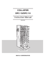
COLLATOR
DFC-12/DFC-10
[220-240V]
ILLUSTRATION : DFC-12

DECLARATION OF CONFORMITY
DUPLO CORPORATION, located at 7-6, Izumi-honcho 1-chome, Komae-shi, Tokyo 201-8666, Japan, declares that the following
product,
• Name of product : Collator
• Models : DFC-12 and DFC-12B, 100-240V 50/60Hz
DFC-10 and DFC-10B, 100-240V 50/60Hz
complies with the provisions defined by the regulations listed below.
• Regulation : Machinery Directive 98/37/EC under EN292-1(1991), EN292-2(1991), prEN1010-1(2002), prEN1010-4(2001),
EN60204-1(1997).
Low Voltage Directive 73 / 23 / EEC under IEC950 2
nd
(1991) + A1 (1992) + A2 (1993) + A3 (1995) + A4 (1996)
including EN60950 2
nd
(1992) + A1 (1993) + A2 (1993) + A3 (1995) + A4(1997) + A11 (1997) deviations.
Electromagnetic Compatibility Directive 89 / 336 / EEC under EN55011(1998) + A1 (1999) Class B, EN55014-2
(1997), EN61000-3-2 (1995) + A1 / A2 (1998) / A14 (2000), EN61000-3-3 (1995), EN61000-6-2:1999.
En
ÜBEREINSTIMMUNGSERKLÄRUNG
Die DUPLO CORPORATION mit Sitz in 7-6, Izumi honcho 1-
chome, Komae-shi, Tokyo 201-8666, Japan, versichert, daß das
folgende produkt,
• Bezeichnung des Produkts :
Zusammentragmaschine
• Modell :
DFC-12 und DFC-12B, 100-240V 50/60Hz
DFC-10 und DFC-10B, 100-240V 50/60Hz
Entspricht den Bestimmungen, wie sie durch die unten
aufgeführten Vorschriften definiert sind.
• Vorschriften :
Maschinenrichtlinie 98/37/EC nach EN292-1(1991), EN292-
2(1991), prEN1010-1(2002), prEN1010-4(2001), EN60204-
1(1997).
Niedervolt-Richtlinie 73/23/EEC nach IEC950 2
nd
(1991) + A1
(1992) + A2 (1993) + A3 (1995) + A4 (1996) und EN60950 2
nd
(1992) + A1 (1993) + A2 (1993) + A3 (1995) + A4(1997) +
A11 (1997) Abweichungen.
EMC-Richtlinie 89/336/EEC nach EN55011(1998) + A1
(1999) Class B, EN55014-2 (1997), EN61000-3-2 (1995) + A1
/ A2 (1998) / A14 (2000), EN61000-3-3 (1995), EN61000-6-
2:1999.
Ge
DECLARATION DE CONFORMITE
DUPLO CORPORATION, située à 7-6, Izumi honcho 1-chome,
Komae-shi, Tokyo 201-8666, Japon, déclare que le produit
suivant ;
• Nom du produit :
Assembleuse
• Modèle :
DFC-12 et DFC-12B, 100-240V 50/60Hz
DFC-10 et DFC-10B, 100-240V 50/60Hz
est conforme aux dispositions définies par les réglementations
suivantes ;
• Réglementations :
Directive sur les machines 98/37/EC en application de EN292-
1(1991), EN292-2(1991), prEN1010-1(2002), prEN1010-
4(2001), EN60204-1(1997)
Directive sur la basse tension 73/23/EEC en application de
IEC950 2
nd
(1991) + A1 (1992) + A2 (1993) + A3 (1995) + A4
(1996) et EN60950 2
nd
(1992) + A1 (1993) + A2 (1993) + A3
(1995) + A4(1997) + A11 (1997) derogations.
Directive de compatibilité électromagnétique 89/336/EEC
d’après EN55011(1998) + A1 (1999) Class B, EN55014-2
(1997), EN61000-3-2 (1995) + A1 / A2 (1998) / A14 (2000),
EN61000-3-3 (1995), EN61000-6-2:1999.
Fr
DICHIARAZIONE DI CONFORMITÁ
DUPLO COPRORATION sita a 7-6,Izumi-honcho 1-chome ,
Komae-shi, Tokyo 201-8666 Japan,dichiara che il seguente
prodotto,
• Nome del prodotto :
Fascicolatore
• Modello :
DFC-12 e DFC-12B, 100-240V 50/60Hz
DFC-10 e DFC-10B, 100-240V 50/60Hz
è conforme ai requisiti definiti dalle norme sotto elencate.
• Direttiva Bassa Tensione :
Direttiva sui macchinari 98/37/CE in base a EN292-1(1991),
EN292-2(1991), prEN1010-1(2002), prEN1010-4(2001),
EN60204-1(1997).
Direttiva relativa alle apparecchiature a bassa tensione 73/23/
CEE in base a IEC950 2
nd
(1991) + A1 (1992) + A2 (1993) +
A3 (1995) + A4 (1996) incluso EN60950 2
nd
(1992) + A1
(1993) + A2 (1993) + A3 (1995) + A4(1997) + A11 (1997)
deviazioni.
Direttiva EMC 89/336/CEE in base a EN55011(1998) + A1
(1999) Class B, EN55014-2 (1997), EN61000-3-2 (1995) + A1
/ A2 (1998) / A14 (2000), EN61000-3-3 (1995), EN61000-6-
2:1999.
It
DECLARACIÓN DE CONFORMIDAD
DUPLO CORPORATION, con domicilio en 7-6, Izumi honcho
1-chome, Komae-shi, Tokio 201-8666 Japan, declara que el
producto siguiente:
• Nombre del producto :
Clasificador
• Modelos :
DFC-12 y DFC-12B, 100-240V 50/60Hz
DFC-10 y DFC-10B, 100-240V 50/60Hz
Cumple las disposiciones definidas por las siguientes
reglamentaciones:
• Reglamentaciones :
Directiva 98/37/CE sobre máquinas bajo EN292-1(1991),
EN292-2(1991), prEN1010-1(2002), prEN1010-4(2001),
EN60204-1(1997).
Directiva sobre baja tensión 73/23/CEE bajo IEC950 2
nd
(1991) + A1 (1992) + A2 (1993) + A3 (1995) + A4 (1996)
incluyendo las derogaciones EN60950 2
nd
(1992) + A1 (1993)
+ A2 (1993) + A3 (1995) + A4(1997) + A11 (1997).
Directiva sobre CEM89/336/CEE bajo EN55011(1998) + A1
(1999) Class B, EN55014-2 (1997), EN61000-3-2 (1995) + A1
/ A2 (1998) / A14 (2000), EN61000-3-3 (1995), EN61000-6-
2:1999.
Sp

1
1. INTRODUCTION
Thank you for your purchase. To ensure correct usage, please read this instruction manual
thoroughly, especially the section Safety Precautions. After reading, please store this
instruction manual in a safe place for future reference.
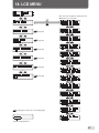
2. TABLE OF CONTENTS
1. INTRODUCTION ............................................. 1
2. TABLE OF CONTENTS .................................. 1
3. SAFETY PRECAUTIONS ................................ 2
4. USAGE PRECAUTIONS ................................. 5
5. FEATURES OF THIS MACHINE ..................... 6
6. NAMES OF PARTS ......................................... 7
7. NAMES AND FUNCTIONS OF
CONTROL PANEL PARTS .............................. 8
8. PRECAUTIONS ON LOADING PAPER .......... 9
9. OPERATIONS................................................ 10
10. LOADING PAPER ACCORDING
TO COLLATION MODE ................................. 15
10-1. Loading paper for normal mode .................... 15
10-2. Loading paper for interleaving mode ............ 16
10-3. Loading paper for alternative mode .............. 16
10-4. Loading paper for block mode....................... 17
10-5. How to load paper when downstream unit
is connected .................................................. 17
10-6. Loading paper according to paper size ......... 18
11. USING THE CONTROL PANEL .................... 19
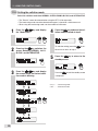
11-1. LCD window .................................................. 19
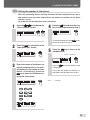
11-2. Setting the collation mode ............................ 20
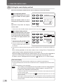
11-3. Setting the number of interleaves ................. 21
11-4. Setting the count display method .................. 22
11-5. Setting the paper receiving method .............. 23
11-6. Other settings ............................................... 24
12. CONNECTING THE DOWNSTREAM UNIT .. 27
12-1. Connecting the DBM-120 and DBM-120T .... 27
12-2. Connecting DC-S and DC-S4 ....................... 33
13. DOUBLE-FEED DETECTION FUNCTION.... 34
14. WHEN BIN ERROR LAMPS LIGHT/BLINK . 36
14-1. When an error lamp lights in green ............... 36
14-2. When an error lamp lights in red................... 36
14-3. When an error lamp blinks in green .............. 37
14-4. When an error lamp blinks in red .................. 37
15. WHEN ERROR MESSAGES
ARE DISPLAYED .......................................... 38
15-1. When "No Paper" is displayed ...................... 38
15-2. When "Tray Full" is displayed ........................ 38
15-3. When "Feed error" is displayed ..................... 39
15-4. When "Preset Error" is displayed .................. 39
15-5. When "Mis-Feed" is displayed ...................... 40
15-6. When "Double Detect" is displayed .............. 40
15-7. When "Paper Jam" is displayed .................... 41
15-8. When "Stacker Jam " is displayed ................ 41
15-9. When "Feed Cov. Open" is displayed ........... 42
15-10.When "Int. Setup Error" is displayed ............. 42
15-11.When "On-line err" is displayed .................... 43
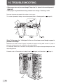
16. TROUBLESHOOTING ................................... 44
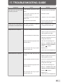
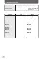
17. TROUBLESHOOTING GUIDE ...................... 45
18. LCD MENU .................................................... 47
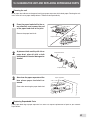
19. CLEANING THE UNIT AND REPLACING
EXPENDABLE PARTS .................................. 51
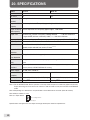
20. SPECIFICATIONS ......................................... 52
Symbols in this Manual
Following symbols are used in this manual to indicate important particulars. They have the following meanings.
Indicates attentions to be paid
in use.
Indicates the page to be referred
to for related information.
Note

2
3. SAFETY PRECAUTIONS
WARNING:
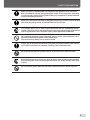
Do not place metal objects or vessels containing liquids on top of the unit. The entry of
any metal object or liquid could result in fire or electrical shock.
Do not insert any metal or easily-combustible object inside this unit. This could result in
fire or electrical shock.
Do not touch or insert foreign objects into any rotating part during operation. This could
result in injury.
Do not remove the cover or back panel. This unit contains high-voltage components that
could cause electrical shock.
Do not disassemble, modify or repair this unit. There is a danger of fire, electrical shock
or injury. Contact your dealer when repairs are necessary.
Use only the power supply voltage specified on the main nameplate. Using other
voltages could result in fire or electrical shock.
Keep this unit and the power cord away from heaters and heater vents. Excessive heat
could melt the cover or power cord covering, and result in fire or electrical shock.
Do not use flammable sprays or solvent inside or near the unit (e.g. when cleaning the
unit).
Such flammable gas or solvent may ignite and cause a fire or combustion.
Always observe the cautions and warnings given below to prevent personal injury or property
damage.
The degree of danger and damage that could occur is indicated on two levels by the
following marks.
WARNING: Ignoring this mark could result in the possibility of serious injury
or even death.
CAUTION: Ignoring this mark could result in the possibility of injury or
physical damage.
The following graphic symbols indicate the various types of action to be performed
or avoided.
This graphic symbol indicates a forbidden action.
means “Do not disassemble.”
means “Do not touch.”
This graphic symbol indicates actions that must be performed.
means “Disconnect the power plug.”

3
3. SAFETY PRECAUTIONS
Make sure that the combined power consumption of the appliances to be connected
does not exceed the capacity rating of the power outlets or plug receptacles. Exceeding
the capacity rating could cause the power outlets, plug receptacles, or power extension
cords to overheat and catch fire.
Remove any dust that accumulates on the power plug prongs and the surface of the plug
from which the prongs extend. Accumulated dust can result in fire.
If any foreign object such as metal or liquid should enter this unit, immediately turn the
unit off at the power switch and disconnect the power plug from the power outlet. Failure
to do so could result in fire or electrical shock. Contact your dealer immediately.
Do not damage the power cord or power plug. (Do not scratch, alter, bend, twist, pull or
place heavy objects on the power cord or power plug.)
This could result in damage, fire or electrical shock.
Always grip the plug when disconnecting the power plug from the power outlet. Pulling
on the power cord could cause damage, resulting in fire or electrical shock.
Do not handle the power plug with wet hands. This could result in electrical shock.
Before cleaning this unit, turn the unit off at the power switch and disconnect the power
plug from the power outlet. Accidental operation of the unit during cleaning could result
in injury.
Do not touch the power switch with wet hands. Otherwise electric hazards may occur.

4
3. SAFETY PRECAUTIONS
CAUTION:
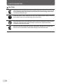
Always disconnect the power plug from the power outlet when the unit is not to be used
for an extended period. Failure to do so could result in fire due to leakage current if the
insulation should deteriorate.
Install this unit on a level, stable stand or floor, with sufficient space around it. Failure to
do so could result in the unit overturning and causing injury.
Do not install this unit in a location where there is excessive humidity or where contact
with water is possible. Poor choice of location could result in deterioration of the
insulation, fire or electrical shock.
Disconnect the power plug from the power outlet before attempting to move this unit.
Failure to do so could result in power cord damage, fire or electrical shock.

5
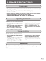
4. USAGE PRECAUTIONS
• This equipment shall be installed near the socket-outlet where the plug on the power supply
cord is easily accessible.
• Make sure the power supply used is always within the following range.
100-240V AC, 50/60Hz
• When you power other appliances from the same AC outlet, make sure that the combined
power consumption does not exceed the power supply capacity.
Rated power of this equipment : 2.8-1.2A(DFC-12) / 2.0-0.8A(DFC-10)
Operating environment
Storage conditions
Maintenance
Operate this unit in the following environment:
• where the temperature range is between
5 and 35°C,
• where the humidity range is between 20
and 85%RH (no dew condensation),
• which is not subject to direct sunlight,
• which is subject to little or no vibration,
• where there are no harmful chemicals,
• which is reasonably free from dust,
• which is free from air-borne salt, and
• where the equipment is not exposed to
water.
Store this unit in the following environment:
• where the temperature range is between
-10 and +50°C,
• where the humidity range is between 10
and 90%RH (no dew condensation),
• which is not subject to direct sunlight,
• which is subject to little or no vibration,
• where there are no harmful chemicals,
• which is reasonably free from dust,
• which is free from air-borne salt, and
• where the equipment is not exposed to
water.
To protect the special features of this unit, the customer should never apply oil or grease to
the parts.
Please contact your dealer in case of any problem.
Power supply

6
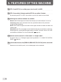
5. FEATURES OF THIS MACHINE
The DFC-12 and DFC-10 can collate paper sizes from A5 to A3SR.
The DFC-12 can collate 12 sheets and the DFC-10 can collate 10 sheets.
By connecting two DFC-12 (DFC-10) machines, up to 24 (20) sheets can be collated.
The following four collation methods are available.
Normal mode: Collates paper on the bins from the top tray in order and ejects as one set.
Interleaving mode: Inserts interleaves after every specified number of sets processed
to separate the collated sets.
Block mode: Divides the paper on the bins into the upper half block and lower half block and
collates paper.
Alternative mode: The same pages can be divided into two piles and stacked on continuing
odd and even bins, and collated taking the two bins as one bin. For details, refer to "10. LOAD-
ING PAPER ACCORDING TO COLLATION MODE" (
page 15).
Collated sets can be received in "offset mode" or "straight mode".
For details, refer to "11-5. Setting the paper receiving method" of "11. USING THE CONTROL
PANEL" (
page 23).
The optional downstream units (DBM-120, DBM-120T, DC-S, DC-S4) can be connected.
Downstream units to bind, punch, or trim collated paper can be connected.

7
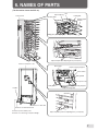
6. NAMES OF PARTS
Control panel
Vertical conveyance cover
Handle
Sliding plate
Movable guide
Paper feed ring
Bin
Fixed guide
Auxiliary paper
feed bin
Connector for other units
Paper feed pressure adjusting knob (on every bin)
Back jogger
Side guide F
Paper receiving table
Paper receiving stopper 2
Side guide B
Power switch
Port for power cord
Paper receiving stopper 1
Paper separation pressure adjusting lever (on every bin)
Connector for downstream unit
Connector port for delivery unit
Used also for connecting conveyance bridge
(The illustration shows the DFC-12)

8
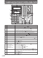
7. NAMES AND FUNCTIONS OF CONTROL PANEL PARTS
No. Name Function
1 Start key Press this key to start operating the unit. ( Page 14)
2 Stop key Press this key to stop the unit. ( Page 14)
3 Preset key Press this key before starting the first collation job. ( Page 14)
Paper for one set is sent from the paper feed bins to memorize the length
and thickness of the paper, and the number of bins used.
4 Eject key Press this key when paper jams. ( Page 41)
The motor will rotate while pressed to eject the jammed paper out.
5 Clear key (C ) Use for clearing the number entered to "0". ( Page 22)
6 Numerical keys (0 to 9) For entering the number of sets to be collated.( Page 22)
7 Scroll key Use this key to scroll the LCD menu.( Page 20)
8 Escape key Press this key to return to the standby screen after completing settings at
the menu screen.( Page 20)
9 Enter key Press this key to change the menu screen and to confirm settings. ( Page
20)
bk NO. OF SETS window Displays the number of collated sets or the number of sets remaining for
collation.( Page 22)
bl LCD window For checking the current operating status of the unit or the current collation
mode.( Page 19)
bm Bin error lamp Lights or blinks at the bin with the paper feed error. ( Page 36,37)
When lit in green: Indicates no paper. ( Page 36)
When blinking in green: Indicates Empty-feed.( Page 37)
When lit in red: Indicates paper has jammed.( Page 36)
When blinking in red: Indicates double-feed.( Page 37)
During presetting, bins with no paper will light up in green.( Page 14)
bn Mode display lamp Indicates the lamp to switch between the offset mode, straight mode, or
optional mode*. (Both lamps will be off when the straight mode is
selected.)( Page 23)
bo Select key Press this key to change the paper ejection direction and paper receiving
method.( Page 23)
*Lights up only when a downstream unit is connected.
321
654
987
C
0
bo
bn
12435
bl bm
8
9
bk
7
6
(The panel is the DFC-12)

9
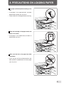
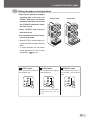
8. PRECAUTIONS ON LOADING PAPER
Fan paper sufficiently before loading on the
bin.
• If the paper is not separated well, mis-feed,
double-feed or paper jam may occur.
• Flatten folded or curled paper before stacking.
Align the lead edge of the paper stock, and
place it on the bin.
• If the paper is not loaded neatly mis-feed, or
double-feed may occur.
Make sure that ink on the paper has dried
completely.
• If not, not only will the unit become dirty, but
other problems (double-feed, mis-feed, paper
jam) may occur.

10
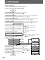
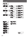
9. OPERATIONS
Flowchart of operations
The following shows the flowchart of the basic operations.
For details, refer to the text and corresponding pages.
Start
1. Turn ON the power switch
2. Adjust the paper feed pressure
3. Adjust the paper separation pressure
4. Load paper on the bin
5. Adjust the position of paper receiving stopper 1
6. Adjust the position of paper receiving stopper 2
7. Adjust the position of side guide F
8. Move the side guide B
9. Set the control panel.
9-1. Set the collation mode
9-3. Set the paper receiving method
9-2. Set the count display method
10. Check paper ejection
11. Start/stop operations
12. Turn OFF the power switch
End
Downstream unit setting
(DBM-120+DBM-120T)
Downstream unit setting
(DC-S,DC-S4)
Set the paper size
Set the binding method
Set the trimmer
Settings after clearing
paper feed error
When using the downstream unit.
( Page14)
( Page20)
• Press the Preset key.
( Page14)
( Page33)
( Page27)
( Page28)
( Page27)
( Page31)
( Page32)
( Page23)
( Page22)
( Page11)
• Set the paper feed pressure adjusting knob to the
paper size. ( Page11)
• Set the paper separation pressure adjusting lever
to the paper thickness. ( Page11)
• The method of stacking paper differs according to
the collation mode used. ( Page15~18)
• Adjust the position to the paper size.
( Page12)
• Adjust the position to the paper size.
( Page12)
• Adjust the position to the paper size.
( Page13)
• Move the side guide B according to the collation
mode offset mode or straight mode.
( Page13)
• Press the Start key.
To stop operations, press
the Stop key.( Page14)

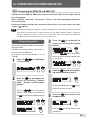
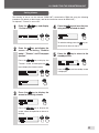
11
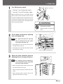
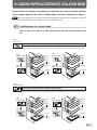
Turn ON the power switch.
• Pressing "I" turns ON the power supply.
Pressing "O" turns OFF the power supply.
When the downstream unit is connected, turning
ON the power switch of the DFC-12/10 will auto-
matically turn ON the power of the downstream unit
as well by the remote function. Be sure to wait for
more than 10 seconds when switching ON again
after having switched OFF.
1
2
WARNING
Do not touch the power
switch with wet hands.
Otherwise electric hazards may
occur.
Set the paper feed pressure adjusting
knob to the paper size.
Note As a paper feed pressure adjusting
knob is provided for each bin, adjust
each knob to the paper size.
• If the paper size is less than A3, set the knob to
the right position (normal).
• If the paper size is more than A3, set the knob to
the left position (strong).
3
Adjust the paper separation pressure
adjusting lever to the paper thickness.
Note As a separator pressure adjusting le-
ver is provided for each bin, adjust each
lever to the paper thickness.
• When using thick paper, move the lever to the
left (where the pressure is low).
• When using normal paper, move the lever to the
center.
• When using thin paper, move the lever to the
right (where the pressure is high).
9. OPERATIONS
OFF
Interruptor de alimentación
ON
Strong
Normal
Paper feed pressure adjusting knob
L
o
w
H
ig
h
Paper separation pressure
adjusting lever

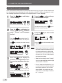
12
9. OPERATIONS
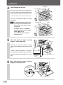
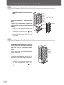
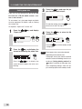
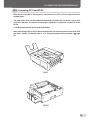
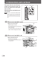
4
Load the paper on the bins.
Insert the paper along the fixed guide until it
touches the guide of the paper feed gate lightly.
• The maximum height of paper which can be
stacked is 28 mm. Be careful not to overstack.
Contact the movable guide lightly to the edge
of the paper.
Note
The method of loading paper differs
according to the normal mode, inter-
leaving mode, block mode, and alter-
native mode.
For details, refer to "10. LOADING
PAPER ACCORDING TO COLLATION
MODE" ( page 15).
Proceed to step 9 when using the
downstream unit.
5
6
Move and adjust the paper receiving
stopper 2 to the paper size.
Move and adjust the paper receiving
stopper 1 to the paper size.
The paper size scale on the paper receiving
table is at the standard position for each paper
size.
If paper is not stacked properly, or if paper is
crushed by the back jogger, adjust the knob to
move the paper receiving stopper 1 back and
forth.
Paper feed gate
Fixed guide
Paper
Movable guide
Paper
Paper receiving stopper 1
Paper receiving
stopper 1
Paper size scale
Paper size
scale
Knob
Paper receiving stopper 2
Paper receiving
stopper 2
Paper size scale

13
9. OPERATIONS
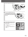
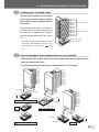
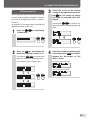
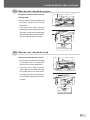
7
Adjust the side guide F to the paper size.
9
Set the collation mode, paper receiving
method, and count display method on
the control panel.
• For details, refer to "11. USING THE CONTROL
PANEL" ( page 19).
• When using the downstream unit, refer to "12.
CONNECTING THE DOWNSTREAM UNIT"
( page 27).
8
When set to the STRAIGHT mode, move
the side guide B until it touches the pa-
per receiving table. When set to the OFF-
SET mode, move it until it
touches the
side frame.
Side guide F
B5
LGL. LTR IV
A4. A5
B4. B5
11x17
Side guide F
Paper size scale
Side guide B
OFFSET mode
Side frame
Paper receiving table
STRAIGHT mode
321
654
987
C
0

14
9. OPERATIONS
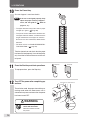
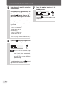
11
Press the Start key and start operations.
To stop operations, press the Stop key.
Turn OFF the power after completing op-
erations.
The collation mode, the paper size and the pro-
cessing mode when the downstream unit is
connected are preserved even after the power
has been turned OFF.
12
WARNING
Do not touch the power
switch with wet hands.
Otherwise electric hazards
may occur.
10
Interruptor de alimentación
ENCENDIDO
APAGADO
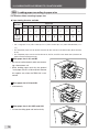
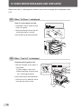
Press the Preset key.
One set of paper is sent from the bin.
Note
If the set is not aligned properly, finely
adjust the paper receiving stoppers 1
and 2, and side guide F. ( Refer to
pages 12, 13.)
• The paper feed error lamp of bins with no paper
will light up in green.( Page 36)
• This preset function differentiates between bins
with paper and those without, and memorizes the
length and thickness of the paper on each bin.
Based on this data memorized, double-feed is
detected.
• For details, refer to "13. DOUBLE-FEED DETEC-
TION FUNCTION" ( page 34).
Take the ejected set and check that the paper
has been collated properly. If not collated prop-
erly, check the location of the error on the con-
trol panel.
Stop key Start key

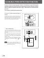
15
10. LOADING PAPER ACCORDING TO COLLATION MODE
Determine how to load paper according to the operation to be carried out after collation.
See the figures below for the order of loading paper on the bins and collation pages.
Note If using the downstream unit, whether to face the printed side up or down differs according to the process-
ing method. Refer to the instruction manual of the downstream unit.
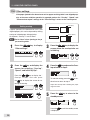
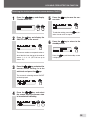
10-1. Loading paper for normal mode
Paper is fed from the top bin in order and ejected to the paper receiving table as one
set.
When paper is loaded with its printed side facing up
When paper is loaded with its printed side facing up, the printed side of the collated paper will face down.
Paper
(When loaded)
Paper
(When ejected)
Paper
(When loaded)
Paper
(When ejected)
Paper
(When loaded)
Paper
(When ejected)
Paper
(When loaded)
Paper
(When ejected)
Paper
(Non-printed side)
When paper is loaded with its printed side facing down
When paper is loaded with its printed side facing down, the printed side of the collated paper will face up.
Paper
(Printed side)
Page 12
Page 1
Page 1
Page 2
Page 3
Page 11
Page 12
Page 12
Page 1
Page 1
Page 2
Page 3
Page 11
Page 12
Page 1
Page 12
Page 12
Page 11
Page 10
Page 2
Page 1
Page 1
Page 12
Page 12
Page 11
Page 10
Page 2
Page 1

16
10. LOADING PAPER ACCORDING TO COLLATION MODE
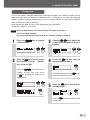
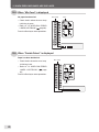
10-2. Loading paper for interleaving mode
10-3. Loading paper for alternative mode
Páginas clasificadas
Page 1
Page 2
Page 3
Page 4
Page 5
Page 6
Page 7
Page 8
Page 9
Páginas para
intercalado
Intercalado
Intercalado
Intercalado
Intercalado
Páge 1
Page 2
Page 3
Page 4
Page 5
Page 6
• Interleaves are inserted after every
specified number of sets have been col-
lated.
• Interleaves are inserted after every 200
sets maximum.
Load the interleaves at the bottommost
bin.
Load in bin 12 for the DFC-12 and in bin
10 for the DFC-10. See the right figure for
details.
• For details on the loading direction of paper
and paper ejection direction, refer to "10-1.
Loading paper for normal mode" ( page
15).
• Interleaving mode is shown as "Int. Lv." in the
LDC window.
Load the same paper on continuing even
and odd (top and bottom) bins from the
top in order (1st and 2nd bins, 3rd and
4th bins....11th and 12th bins) for colla-
tion.
Paper feed starts from either bin (odd or
even) of each pair.
If paper runs out in a bin, paper feed will
start from the other bin in the pair. By re-
plenishing paper in the empty bin, continu-
ous operations can be ensured.
• For details on the loading direction of paper
and paper ejection direction, refer to "10-1.
Loading paper for normal mode" ( page
15).

17
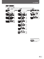
10. LOADING PAPER ACCORDING TO COLLATION MODE
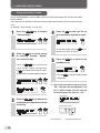
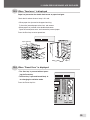
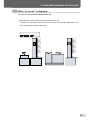
10-5. How to load paper when downstream unit is connected
• Paper ejected from the DFC-12/10 is punched, stapled, folded, and trimmed as shown
below by a downstream units.
• The interleaving mode cannot be set if a downstream unit is connected.
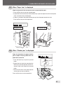
10-4. Loading paper for block mode
Page 1-a
Page 2-a
Page 3-a
Page 4-a
Page 5-a
Page 6-a
Page 1-b
Page 2-b
Page 3-b
Page 4-b
Page 5-b
Page 6-b
Group of block 1/2
Group of block 2/2
Group of block 1/2
Group of block 2/2
DC-SP
DBM-120 + DBM-120T
DC-S4
DC-S
DC-S4 (When attaching the option)
DC-S
Página 1
Page 2
Page 3
Page 4
Page 5
Page 6
Page 7
Page 8
Page 9
Page 10
Page 11
Page 12
Page 1
Page 2
Page 3
Page 4
Page 5
Page 6
Page 7
Page 8
Page 9
Page 10
Page 11
Page 12
Page 1
Page 2
Page 3
Page 4
Page 5
Page 6
Page 7
Page 8
Page 9
Page 10
Page 11
Page 12
Page 1
Page 12
Page 1
Page 12
Punched holes
Corner stapling
Corner stapling
Side stapling
Side stapling
Side stapling
Side stapling
Saddle stapling
Saddle stapling
DC-S4 (When attaching the option)
Page 1
Page 12
DBM-120
The bins can be divided into two blocks
(6 bins each) to collate paper in blocks.
For the DFC-10, bins are divided likewise
5 bins each.
Paper feed starts from bins 1 to 6 (block 1/
2). When paper on any bin of the block runs
outs, operation is stopped. Press the Start
key to switch paper feed to bins 7 to 12 (block
2/2).
• For details on the loading direction of paper
and paper ejection direction, refer to "10-1.
Loading paper for normal mode" ( page
15).

18
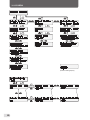
A5 A4 A3 A3SR B5 B4 LGL LTR LGR INV
%????????%
??XX? XX? X ?
10. LOADING PAPER ACCORDING TO COLLATION MODE
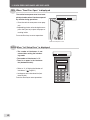
10-6. Loading paper according to paper size
The direction differs according to paper size.
● Paper loading direction available
When paper size is A5, and INV
• Be sure to load horizontally when not connect-
ing a downstream unit.
• When loading paper vertically, the optional
"small paper size kit" will be required. However
this applies only when the DBM-120 is con-
nected.
When paper size is B4 and LGL
• Load vertically.
When paper size is A3, A3SR, and LGR
• Pull out the sliding plate and load vertically.
? : Available X : Not available % : Available when DBM-120 and DBM-120T are connected
• LGL = Legal (8.5” x 14”) LTR = Letter (8.5” x 11”) INV = Invoice (8.5” x7”) LGR = Double letter (11” x
17”)
• The compatible paper sizes for the DC-S are A4, B5, B4, and LGL in the above table. (Stack vertically
for all)
• The compatible paper sizes for the DC-S4 are A5, A4, B5, and LTR in the above table. (However A5
paper cannot be loaded vertically)
Direction
Paper size
Sliding plate
⇑
⇑
La pagina sta caricando ...
La pagina sta caricando ...
La pagina sta caricando ...
La pagina sta caricando ...
La pagina sta caricando ...
La pagina sta caricando ...
La pagina sta caricando ...
La pagina sta caricando ...
La pagina sta caricando ...
La pagina sta caricando ...
La pagina sta caricando ...
La pagina sta caricando ...
La pagina sta caricando ...
La pagina sta caricando ...
La pagina sta caricando ...
La pagina sta caricando ...
La pagina sta caricando ...
La pagina sta caricando ...
La pagina sta caricando ...
La pagina sta caricando ...
La pagina sta caricando ...
La pagina sta caricando ...
La pagina sta caricando ...
La pagina sta caricando ...
La pagina sta caricando ...
La pagina sta caricando ...
La pagina sta caricando ...
La pagina sta caricando ...
La pagina sta caricando ...
La pagina sta caricando ...
La pagina sta caricando ...
La pagina sta caricando ...
La pagina sta caricando ...
La pagina sta caricando ...
La pagina sta caricando ...
La pagina sta caricando ...
-
 1
1
-
 2
2
-
 3
3
-
 4
4
-
 5
5
-
 6
6
-
 7
7
-
 8
8
-
 9
9
-
 10
10
-
 11
11
-
 12
12
-
 13
13
-
 14
14
-
 15
15
-
 16
16
-
 17
17
-
 18
18
-
 19
19
-
 20
20
-
 21
21
-
 22
22
-
 23
23
-
 24
24
-
 25
25
-
 26
26
-
 27
27
-
 28
28
-
 29
29
-
 30
30
-
 31
31
-
 32
32
-
 33
33
-
 34
34
-
 35
35
-
 36
36
-
 37
37
-
 38
38
-
 39
39
-
 40
40
-
 41
41
-
 42
42
-
 43
43
-
 44
44
-
 45
45
-
 46
46
-
 47
47
-
 48
48
-
 49
49
-
 50
50
-
 51
51
-
 52
52
-
 53
53
-
 54
54
-
 55
55
-
 56
56


Duplo DFC-10 Manuale utente
- Tipo
- Manuale utente
- Questo manuale è adatto anche per
in altre lingue
- English: Duplo DFC-10 User manual
Documenti correlati
Altri documenti
-
Panasonic Panafax UF-490 Manuale utente
-
Minolta CF 9001 Manuale utente
-
Panasonic UF4100 Istruzioni per l'uso
-
Cisco Systems AS5400XM Manuale utente
-
Konica Minolta EP1085 Manuale del proprietario
-
HP Color Inkjet cp1700 Printer series Guida utente
-
-
-