La pagina si sta caricando...

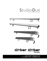
User manual
Manuale d’uso
RGBW
Monochromatic
White balance
RDM

2
rel.7.1 - 07/21 - Studio Due
INDEX
Page 3 - Mounting instructions - Istruzioni di montaggio
Page 7 - Safety informations / Informazioni di sicurezza
Page 8 - Introduction / Introduzione
Page 9 - Technical features / Caratteristiche tecniche
Page 11 - Example of connection DMX controller-xtures / Esempio di collegamento centralina DMX-fari
Page 12 - Main supply connection / Collegamento fonte di alimentazione
Page 13 - DMX signal connection / Collegamento segnale DMX
Page 14 - Setup and conguration of DRS Setup - Congurazione del DRS Setup
Page 16 - Menu list / Lista menu
Page 17 - DMX Listing / Lista dei canali DMX
Page 20 - Physical / Dimensioni
Page 21 CE standards / Certicazioni CE
Page 22 - Warranty / Garanzia

3rel.7.1 - 07/21 - Studio Due
IMPORTANT BEFORE MOUNTING / IMPORTANTE PRIMA DEL MONTAGGIO
FORMWORK
DRAINAGE
ground level
!
!Be sure to create sufficient drainage around the formwork.
fixture
DMX IN
MAIN IN
to be connected to
a waterproof box
(not included)
Assembly operations must be carried out by qualified personnel.
!NOT SUITABLE FOR VEHICLES
NON CARRABILE
!the formwork
must be earthed

4
rel.7.1 - 07/21 - Studio Due
TOP
TOP
TOP
aa
TOP
IMPORTANT
!
INSTRUCTIONS FOR THE CORRECT APPLICATION OF THE SLEEVE OF THE
FIXTURES. ALL VERSIONS.
ISTRUZIONI PER LA CORRETTA POSA IN OPERA DELLA CASSAFORMA DEGLI
APPARECCHI. TUTTE LE VERSIONI.
Position (t) and screw on the sleeve the rst adjustment plate (p1).
In the opposite position t and screw the second adjustment plate (p2) as shown in the picture (a).
The sleeve is provided with a cover (p0).
PAY ATTENTION TO THE TOP POSITIONING TOWARDS UPWARDS.
POSITION THE TWO REGISTERS IN THE POINTS MOST SUITABLE FOR ASSEMBLY.
a)
b) Insert the sleeve in the hole created to house the appliance so that the adjustment plates (p1 and p2) are at the nished installation level (f) and
in the correct position on the support surface.
Posizionare la cassaforma nel foro creato per alloggiare l’apparecchio in modo che le piastre di registro (p1 e p2) si trovino al livello nito di
installazione (f) e in posizione corretta sul piano di appoggio.
Posizionare (inserire) e avvitare sulla cassaforma il primo registro di livello terra (p1) nella posizione più idonea in base al terreno.
Nella posizione opposta, ssare e avvitare la seconda piastra di registro (p2) come mostrato nella gura (a).
La cassaforma è fornita di coperchio (p0).
FARE ATTENZIONE AL VERSO DI POSIZIONAMENTO TOP VERSO L’ALTO.
POSIZIONARE I DUE REGISTRI NEI PUNTI PIU’ IDONEI AL MONTAGGIO.
finished installation level (f)
CORRECT FIXING OF THE SLEEVE - CORRETTO FISSAGGIO DELLA CASSAFORMA
Sleeve / Cassaforma
(c)
Excavation for sleeve /
Scavo per cassaforma
(p1) (p2)
(p0)
(p2)
It is possible that the sleeve is supplied with the ARCHIBAR already assembled.
In this case, unscrew the appliance from the formwork and proceed as described in point (a).
E’ possibile che la cassaforma venga fornita con la ARCHIBAR già montata.
In questo caso svitare l’apparecchio dalla cassaforma e procedere come descritto dal punto (a).

5rel.7.1 - 07/21 - Studio Due
d) Remove the plates p1, p2 and p0. The sleeve is now correctly positioned.
Rimuovere le piastre p1, p2 e p0. La cassaforma è ora posizionata in modo corretto.
Wire and place the appliance in the sleeve and screw the supplied screws.
Cablare e posizionare l’apparecchio nella cassaforma e avvitare le viti in dotazione.
TOP
TOP
a
TOP
a
finished installation level (f)
c) The plates p1 and p2 positioned in this way, allow to cement the sleeve in the correct position with the nished
installation level (f). See picture (c).
Le piastre p1 e p2 posizionate in questo modo, consentono di cementare la cassaforma nella posizione corretta con il
livello nito di installazione (f).
Vedi immagine (c).
(p1)
(p2)
e)

6
rel.7.1 - 07/21 - Studio Due
0°
Position
0°
lens 60°
LIGHTING SURFACE
0°
0
lens 40°
lens 25°
lens 15°
lens 8°
3°
Position
3°
3°
3°
LIGHTING SURFACE
6°
Position
6°
6°
6
LIGHTING SURFACE

7rel.7.1 - 07/21 - Studio Due
IK10
IK10
eng
WARNING
!SAFETY INFORMATION (service personnel)
READ ALL CAUTIONS AND WARNINGS PRIOR TO OPERATE THIS EQUIPMENT.
INSTRUCTION TO PREVENT INJURY OR DAMAGE DUE TO ELECTRIC SHOCK, FIRE, MECHANICAL HAZARDS,
DANGEROUS MATTERS.
•PROTECTION AGAINST FIRE
1) Maintain minimum distance of 0,1 meter to lighted objects.
2) Replace fuses (if present) only with the specied type and rating.
3) Do not install the xture close to heat sources. Do not lay the connection cable on the xture when it is warm.
4) Fixture designed to be installed on normally ammable surfaces.
•PROTECTION AGAINST ELECTRIC SHOCK
1) This equipment and the formwork (sleeve) must be earthed.
2) Class I equipment. The power supply cord includes a protective earthing conductor as part of the cord.
3) Disconnect power before servicing (service personnel).
4) To replace the LEDs, contact: Studio Due Trade Srls.
5) If the external exible cable of this appliance is damaged, it must only be replaced by the manufacturer,
its assistance service, or equivalent qualied personnel, in order to avoid dangers.
•PROTECTION AGAINST MECHANICAL HAZARDS
1) The protection screens and the lenses must be replaced with genuine parts only if they are visibly damaged and
their effectiveness has been reduced, for example, by cracks or deep scratches.
2) Do not look directly into the illuminated LEDs of the product for long periods of time. LED lamps can cause eye
damage or irritation. Do not look directly into the light source using an optical instrument that focuses on
the light beams.
The device should be positioned so that there is no prolonged observation of the device at a distance
of less than 100cm. (RG1 – IEC/TR 62778:2014).
•PROTECTION AGAINST DANGEROUS MATTERS
At the end of its life, must be collected separately. It shouldn’t be thrown as urban waste and neither released in the envi-
ronment.
It must be collected from the nearest special waste collection point or consigned to your dealer that provides the service.
The incorrect waste disposal can damage the environment and the people for the presence of dangerous substances.
Sanctions are provided for an unauthorized disposal.
INFORMAZIONI DI SICUREZZA (personale di servizio)
LEGGERE ATTENTAMENTE TUTTI GLI AVVERTIMENTI PRIMA DI COMPIERE QUALUNQUE OPERAZIONE SU QUESTO
APPARECCHIO. ISTRUZIONI PER PREVENIRE LESIONI O DANNI DOVUTI AL FUOCO, ALLE SCOSSE ELETTRICHE,
AI RISCHI MECCANICI ED A SOSTANZE PERICOLOSE.
•PROTEZIONE CONTRO IL FUOCO
1) Mantenere la distanza minima di 0,1 metri dagli oggetti illuminati.
2) Sostituire i fusibili (se presenti) solo con altri dello stesso tipo e valore.
3) Non installare il faro vicino fonti di calore. Non appoggiare il cavo di connessione sul faro quando questo è caldo.
4) Questo apparecchio è adatto per il montaggio su superci normalmente inammabili.
•PROTEZIONE CONTRO SCOSSE ELETTRICHE
1) Questo apparecchio e la cassaforma necessitano di messa a terra.
2) Apparecchio di Classe I. Il conduttore di protezione deve far parte del cavo di alimentazione.
3) Disconnettere l’alimentazione prima di aprire l’apparecchio (personale di servizio).
•PROTEZIONE CONTRO RISCHI MECCANICI
1) Gli schermi di protezione e le lenti devono essere sostituiti sempre con ricambi originali
se sono visibilmente danneggiati e se la loro efcacia è stata ridotta, per esempio, da fessure o incisioni profonde.
2) Non guardare direttamente nei LED illuminati del prodotto per lunghi periodi di tempo. Le lampade a LED possono
causare danni o irritazione agli occhi. Non guardare direttamente nella sorgente luminosa utilizzando uno strumento
ottico che si concentra sui fasci di luce. L’apparecchio dovrebbe essere posizionato in modo che non sia prevista
un’osservazione prolungata dell’apparecchio ad una distanza inferiore di 100cm. (RG1 – IEC/TR 62778:2014).
IMPORTANTE
!
•PROTEZIONE CONTRO SOSTANZE PERICOLOSE
A ne vita è oggetto di raccolta separata, non gettare nei comuni cassonetti di riuti urbani, né tantomeno nell’ambien-
te. Può essere consegnato presso gli appositi centri di raccolta differenziata predisposti dalle amministrazioni comunali,
oppure presso i rivenditori che forniscono questo servizio. Lo smaltimento errato può causare danni alle persone e all’am-
biente per la possibile presenza di sostanze pericolose. Sono previste sanzioni in caso di smaltimento abusivo dei suddetti
prodotti.
ita

8
rel.7.1 - 07/21 - Studio Due
WARNING
!
Check that the fixture has not been damaged during transport. If it has been damaged or it does not work, address the
seller. Whether the fixture has been shipped to you directly, please contact the shipping company.
Only the consignee (person or company) can claim for these damages.
INTRODUCTION
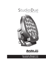
Thanks for using Archibar SL150-inground RDM.
Available in RGBW/FC and MONOCHROMATIC light source as well as in WHITE BALANCE all with manual TILT 0-6°.
INGROUND LED linear bar which combines aesthetic and resistance with ideal performanc in a versatile projector.
Waterproof and tremendously resistant. Standard 90cm. On request 60cm. and 30cm.
NOT SUITABLE FOR VEHICLES.
• Art. 204014 Archibar SL150-i RDM RGBW
• Art. 204214 Archibar SL150-i RDM WB White Balance
• Art. 204114 Archibar SL150-i RDM M Monochromatic - DIMMABLE
• Art. 204104 Archibar SL150-i M Monochromatic - PLUG-IN
To obtain the best performances and for a correct functioning of this unit for the years to come, we suggest you to read carefully this
manual before connecting or putting the xture into use. By doing so you will gain experience with its commands and connections and
you will be easily able to use it.
YOUR REFERENCE
Always remember to give the serial number and to specify the model any time you address the seller for information or assistance.
BASIC KIT
• Projector + formwork (sleeve)
• User manual
• Studio Due warranty
• CE standards
INTRODUZIONE
Vi ringraziamo per l’utilizzo del nostro Archibar SL150-inground RDM.
Disponibile in versione RGBW, MONOCROMATICA e WHITE BALANCE tutte con TILT manuale 0-6°.
Barra lineare LED INGROUND che combina estetica e resistenza con prestazioni eccezionali in un proiettore versatile.
Impermeabile e altamente resistente. Standard 90cm. A richiesta 60cm. e 30cm.
NON CARRABILE.
• Art. 204014 Archibar SL150-i RDM RGBW
• Art. 204214 Archibar SL150-i RDM WB White Balance
• Art. 204114 Archibar SL150-i RDM M Monochromatic - DIMMERABILE
• Art. 204104 Archibar SL150-i M Monochromatic - PLUG-IN
Per ottenere il meglio delle prestazioni ed un corretto funzionamento negli anni di questa unità, Vi consigliamo di leggere
attentamente questo manuale prima di collegarla e metterla in uso. In questo modo acquisirete familiarità con i suoi comandi
e collegamenti afnché possiate utilizzarla facilmente.
VOSTRA REFERENZA
Citate sempre il numero del modello e di serie ogni volta che Vi rivolgete al vostro rivenditore per informazioni o assistenza.
CONFEZIONE BASE
• Proiettore + cassaforma
• Manuale d’uso
• Garanzia Studio Due
• Dichiarazione CE
Controllate che l’apparecchio non abbia subito alcun danno durante il trasporto.
Se avesse subito dei danni o se non dovesse funzionare, rivolgetevi al vostro rivenditore.
Se l’apparecchio vi è stato spedito direttamente, rivolgetevi subito alla ditta di trasporto.
Solo il destinatario (la persona o ditta ricevente l’apparecchio) può reclamare per questo tipo di danni.
IMPORTANTE
!
eng
ita

9rel.7.1 - 07/21 - Studio Due
TECHNICAL FEATURES / CARATTERISTICHE TECNICHE
• SOURCE
n. 12 (5050-20W-RTBH) LEDs
Total out lumen: R 750, G 1800, B 250, W 1600
• OPTIC (38 mm lenses)
8°, 15°, 25°, 40°, 60° or 15°x30° beam
filters: 17°, 34°, 60°, 100°, 8°x60°
• TILT
manual 0°, 3°, 6°
• CONTROL
Standard interface: RS-485
Protocol: USITT DMX 512 / RDM
• CONNECTIONS
Signal: 3pin cable 100cm. (could be wired with 4PIN connector)
Available as accessories:
- Wireless DMX receiver
Main Power: 3pin cable 100cm. with bare ends
• SETUP AND CONFIGURATION
RDM Control/configuration or
individually by DRS (remote control device)
Dedicated DMX channel for white balance
DMX or Auto mode with Master-Slave function
Intelligent temperature control
Halogen simulation
CYM simulation
Flicker-free function
Smooth dimming function
• IP67 RATING PROTECTION
• IK10 RATING
• POWER SUPPLY
Voltage range: 100-277VAC
Frequency range: 47-63Hz
Active Power factor:
PF>0.97@230VAC
Current: 0.2A@230VAC
Power: 45W
Fuse T3,15A (inside fixture)
• DMX CHANNELS
9CH mode, 6CH mode, 5CH mode, 4CH mode
• PHYSICAL
WxDxH: 1063x182x133 mm
Weight: 15 Kg.
BGR A
WW W
warm neutral cool 2700K 6500K
• SOURCE
n. 24 warm, neutral, cool LEDs monochromatic
n. 12 (2700K) + 12 (6500K) white balance
On request: red, green, blue or amber
Total lumen: 7500 (monochromatic) - 6000 (white balance)
• OPTIC (38 mm lenses)
Monochromatic: 4° plug-in, 8°, 15°, 40°, 60°, 15°x30° beam
White balance: 8°, 15°, 40°, 60°, 15°x30° beam
filters: 17°, 34°, 60°, 100°, 8°x60° (4°x60° plug-in)
• TILT
manual 0°, 3°, 6°
• CONTROL
Standard interface: RS-485
Protocol: USITT DMX 512 / RDM
• CONNECTIONS
Signal: 3pin cable 100cm. (could be wired with 4PIN connector)
Available as accessories:
- Wireless DMX receiver
Main Power: cable 100cm. with bare ends
• SETUP AND CONFIGURATION
RDM Control/configuration or
individually by DRS (remote control device)
Dedicated DMX channel for white balance
DMX or Auto mode with Master-Slave function
Intelligent temperature control
Halogen simulation
Flicker-free function
Smooth dimming function
• IP67 RATING PROTECTION
• IK10 RATING
• POWER SUPPLY
Voltage range: 100-277VAC
Frequency range: 47-63Hz
Active Power factor:
PF>0.97/230VAC
Current: 0.2A@230VAC
Power: 50W (M) - 50W (WB) - 45W (plug-in)
Fuse T3,15A (inside fixture)
• DMX CHANNELS
4CH mode, 2CH mode, 1CH mode (white balance)
3CH mode, 1CH mode (monochromatic)
• PHYSICAL
WxDxH: 1063x182x133 mm
Weight: 15 Kg.
For PLUG IN version
- Main Power: cable 100cm.
- NO CONTROL
- NO SETUP and CONFIGURATION
- NO DMX CHANNELS
standard 90cm standard 90cm

10
rel.7.1 - 07/21 - Studio Due
TECHNICAL FEATURES / CARATTERISTICHE TECNICHE
BGR A
WW W
warm neutral cool 2700K 6500K
technical features for ARCHIBAR INGROUND 60cm
• SOURCE
n. 8 (5050-20W-RTBH) LEDs
Total out lumen: R 500, G 1200, B 170, W 1070
• OPTIC (38 mm lenses)
8°, 15°, 25°, 40°, 60° or 15°x30° beam
filters: 17°, 34°, 60°, 100°, 8°x60°
......................
• POWER SUPPLY
Voltage range: 100-277VAC
Frequency range: 47-63Hz
Active Power factor:
PF>0.97@230VAC
Current: 0.16A@230VAC
Power: 37W
Fuse T3,15A (inside fixture)
• PHYSICAL
WxDxH: 763x182x173 mm
• SOURCE
n. 16 warm, neutral, cool LEDs monochromatic
On request: red, green, blue or amber
n. 8 (2700K) + 8 (6500K) white balance
Total lumen: 5000 (monochromatic) - 4000 (white balance)
• OPTIC (38 mm lenses)
Monochromatic: 4° plug-in, 8°, 15°, 40°, 60°, 15°x30° beam
White balance: 8°, 15°, 40°, 60°, 15°x30° beam
filters: 17°, 34°, 60°, 100°, 8°x60° (4°x60° plug-in)
......................
• POWER SUPPLY
Voltage range: 100-277VAC
Frequency range: 47-63Hz
Active Power factor:
PF>0.97/230VAC
Current: 0.14A@230VAC
Power: 34W (M) - 34W (WB) - 30W (plug-in)
Fuse T3,15A (inside fixture)
• PHYSICAL
WxDxH: 763x182x173 mm
For PLUG IN version
- Main Power: cable 100cm.
- NO CONTROL
- NO SETUP and CONFIGURATION
- NO DMX CHANNELS
technical features for ARCHIBAR INGROUND 30cm
• SOURCE
n. 4 (5050-20W-RTBH) LEDs
Total out lumen: R 250, G 600, B 90, W 540
• OPTIC (38 mm lenses)
8°, 15°, 25°, 40°, 60° or 15°x30° beam
filters: 17°, 34°, 60°, 100°, 8°x60°
......................
• POWER SUPPLY
Voltage range: 100-277VAC
Frequency range: 47-63Hz
Active Power factor:
PF>0.97@230VAC
Current: 0.13A@230VAC
Power: 20W
Fuse T3,15A (inside fixture)
• PHYSICAL
WxDxH: 463x182x173 mm
technical features for ARCHIBAR INGROUND 60cm
• SOURCE
n. 8 warm, neutral, cool LEDs monochromatic
n. 4 (2700K) + 4 (6500K) white balance
On request: red, green, blue or amber
Total lumen: 2500 (monochromatic) - 2000 (white balance)
• OPTIC (38 mm lenses)
Monochromatic: 4° plug-in, 8°, 15°, 40°, 60°, 15°x30° beam
White balance: 8°, 15°, 40°, 60°, 15°x30° beam
filters: 17°, 34°, 60°, 100°, 8°x60° (4°x60° plug-in)
......................
• POWER SUPPLY
Voltage range: 100-277VAC
Frequency range: 47-63Hz
Active Power factor:
PF>0.97/230VAC
Current: 0.1A@230VAC
Power: 25W (M) - 25W (WB) - 15W (plug-in)
Fuse T3,15A (inside fixture)
• PHYSICAL
WxDxH: 463x182x173 mm
For PLUG IN version
- Main Power: cable 100cm.
- NO CONTROL
- NO SETUP and CONFIGURATION
- NO DMX CHANNELS
technical features for ARCHIBAR INGROUND 30cm

11 rel.7.1 - 07/21 - Studio Due
EXAMPLE OF CONNECTION DMX CONTROLLER - FIXTURES / ESEMPIO DI COLLEGAMENTO CENTRALINA - FARI
DMX
¿[WXUH ¿[WXUH ¿[WXUH ¿[WXUH
TL
NORMAL
$GGUHVV
VHWXSFK
&
$GGUHVV
VHWXSFK
&
$GGUHVV
VHWXSFK
=C007
$GGUHVV
VHWXSFK
&
¿[WXUH ¿[WXUH ¿[WXUH
TL
MASTER/SLAVE
6HWXS 0$67(5 VHWXS 6/$9( VHWXS 6/$9( VHWXS 6/$9(
¿[WXUH
NORMAL AND MASTER/SLAVE FUNCTIONS / FUNZIONI NORMAL E MASTER/SLAVE
Example 1/ Esempio 1
DMX
/DVW¿[WXUH
8OWLPRIDUR
7HUPLQDWLRQUHVLVWRU
7HUPLQDOHGLOLQHD
Example 2 / Esempio 2
DMX
/DVW¿[WXUH
8OWLPRIDUR
7HUPLQDWLRQUHVLVWRU
7HUPLQDOHGLOLQHD
OLQHOLQHD
7HUPLQDWLRQUHVLVWRU
7HUPLQDOHGLOLQHD
OLQHOLQHD
'0;RXW '0;RXW
&RQQHFWLRQFRQWUROOHUVSRWWR
'0;RXWSXWRYHUPWORQJ
&ROOHJDPHQWRFHQWUDOLQDVSRWDGXQDVROD
OLQHDGLXVFLWD'0;OXQJDROWUHPW
/,1(!PWZLWKPLFURSKRQLFRUDXGLRFDEOH
/,1($!PWFRQFDYRPLFURIRQLFRRDXGLR
DMX
7HUPLQDWLRQUHVLVWRU
7HUPLQDOHGLOLQHD
Example 3 / Esempio 3
6,*1$/$03/,),(5
$03/,),&$725(
',6(*1$/(
/DVW¿[WXUH
8OWLPRIDUR
/DVW¿[WXUH
8OWLPRIDUR
'0;RXW
'0;RXW
TL=
7HUPLQDO/LQH
IRUH[DPSOH¿[WXUHVHWXSDWFKDQQHOV
TL
TL
TL
TL
¿[WXUH
DSSDUHFFKLR
¿[WXUH
DSSDUHFFKLR
¿[WXUH
DSSDUHFFKLR
¿[WXUH
DSSDUHFFKLR
¿[WXUH
DSSDUHFFKLR
¿[WXUH
DSSDUHFFKLR ¿[WXUH
DSSDUHFFKLR
¿[WXUH
DSSDUHFFKLR
¿[WXUH
DSSDUHFFKLR
¿[WXUH
DSSDUHFFKLR
FRQQ
ER[
FRQQ
ER[
¿[WXUH
DSSDUHFFKLR
¿[WXUH
DSSDUHFFKLR
FRQQ
ER[
FRQQ
ER[
¿[WXUH
DSSDUHFFKLR
¿[WXUH
DSSDUHFFKLR
FRQQ
ER[
FRQQ
ER[
¿[WXUH
DSSDUHFFKLR
¿[WXUH
DSSDUHFFKLR
FRQQ
ER[
FRQQ
ER[
¿[WXUH
DSSDUHFFKLR ¿[WXUH
DSSDUHFFKLR
FRQQ
ER[ FRQQ
ER[
¿[WXUH
DSSDUHFFKLR
¿[WXUH
DSSDUHFFKLR
FRQQ
ER[
FRQQ
ER[
¿[WXUH
DSSDUHFFKLR
¿[WXUH
DSSDUHFFKLR
FRQQ
ER[
FRQQ
ER[
FRQQ
ER[
FRQQ
ER[
FRQQ
ER[
FRQQ
ER[
FRQQ
ER[
FRQQ
ER[
FRQQ
ER[

12
rel.7.1 - 07/21 - Studio Due
MAIN IN
Ingresso rete
70cm. circa
DMX IN
Ingresso DMX
about 70cm.
WATERPROOF
connection box
(not included)
DMX line
WATERPROOF
connection box
(not included)
MAINS
NOT PRESENT for
PLUG-IN version
NON PRESENTE nella
versione PLUG-IN
CONNECTION TO THE MAIN POWER / CONNESSIONE ALLA RETE ELETTRICA
This equipment must be earthed.
Class I equipment. The power supply cord includes a protective earthing conductor as part of the cord.
IMPORTANT: to ensure the IP67 protection rating, in case of replacement of the conductor cable, refer to the CONDUCTOR SIZE TABLE
Questo apparecchio necessita di messa a terra.
Apparecchio di Classe I. Il conduttore di protezione deve far parte del cavo di alimentazione.
IMPORTANTE: per garantire il grado di protezione IP67, in caso di sostituzione del cavo di alimentazione, fare riferimento alla TABELLA
SEZIONE CONDUTTORE.
eng
ita
WARNING
!
HIGH VOLTAGE!
Always disconnect the mains supply before access to the connection area.
ALTA TENSIONE!
Scollegare sempre l’alimentazione prima di aprire il vano dei collegamenti.
CONDUCTOR SIZES / SEZIONE CONDUTTORE (length /
lunghezza < 20mt.)
MAINS VOLTAGE CROSS SELECTIONAL AREAS
230V 3X1 mm2 (minimum)
POWER INPUT/
INGRESSO ALIMENTAZIONE Ø 6 - 12mm
Metal
Anti-Condensation Valve
Per accedere all’interno della
cassaforma svitare le 10 viti poste
nella angia in acciaio.
MAINS CONNECTION
FRPPHUFLDO!,3FRQQHFWLRQER[
127,1&/8'('
To access inside the formwork,
unscrew the 10 screws placed in
the steel ange.
to the xture
MAIN IN
to other xture
MAINS
Valvola anticondensa
in metallo
BROWN / 100/277Vac - 50-60Hz
BLUE / NEUTRAL
GREEN-YELLOW / GROUND
MAIN IN connection
UNIVERSAL MAIN VOLTAGE
100-277V~ / 50-60Hz

13 rel.7.1 - 07/21 - Studio Due
DMX TERMINAL LINE
The wrong connection of the terminal line or its non-connection are probably the most frequent reasons for the defective functioning of
the DMX line. The terminator is a terminal resistor tted at the end of the cable furthest from the transmitter.
The terminal resistor should have the same value as the impedance of the connection cable.
We suggest to use a terminal with a 120 Ohm resistor.
It is recommanded that all DMX 512 systems have the terminal resistor tted in the DMX output of the last xture.
TERMINALE LINEA DMX
L’incorretto o il mancato collegamento del terminale di linea è probabilmente la più comune causa del difettoso funzionamento della
linea DMX. Il terminale di linea DMX consiste in una resistenza posta alla ne della linea.
La resistenza terminale dovrebbe avere idealmente lo stesso valore dell’impedenza del cavo di collegamento.
Noi consigliamo di usare come terminale una resistenza da 120 Ohm.
E’ raccomandato per tutti i sistemi DMX 512 inserire il teminale di linea nel connettore uscita DMX dell’ultimo apparecchio collegato.
eng
ita
CONNECTION TO THE DMX SIGNAL / CONNESSIONE AL SEGNALE DMX
example of
label on the rear
of the xture
SHIELD / GND
RED / DMX -
ORANGE / DMX +
DMX connection cable
DMX CONNECTION
FRPPHUFLDO!,3FRQQHFWLRQER[
127,1&/8'('
to the xture
DMX IN
DMX DMX

14
rel.7.1 - 07/21 - Studio Due
SETUP and CONFIGURATION by DRS - DMX REMOTE SETUP
SETTAGGIO e CONFIGURAZIONE tramite DRS - DMX REMOTE SETUP
The DRS it’s a new concept of professional LED Lighting xtures suitable for outdoor permanent installations.
The LED Lighting xtures can be driven via DMX through a specic electronic device, the DRS DMX Remote Setup, that grant the
possibility to set up the scenarios and the games remotely.
These LED Lighting xtures have installed on board a series of programs including the stand alone function.
The DRS is a simple set up commander that linked with the DMX input of a LED Lighting xture allow to program all the functions of
the luminaire.
It’s than possible to assign the DMX channel or use the Master/Slave function.
The device is powered through battery.
DMX line
XLR - LLT
connector
MAIN Power
Powered through
battery
DRS è il nuovo concetto dell’illuminazione LED per uso professionale nelle installazioni esterne permanenti.
Gli apparecchi LED possono essere controllati e congurati tramite uno specico controller: il DRS, DMX Remote Setup, il quale consente
di programmare e congurare scene e giochi di luce in modalità remota.
Questi apparecchi LED hanno installati a bordo una serie di giochi che includono la funzione stand alone.
Il DRS, DMX Remote Setup, è un semplice set-up commander che collegato via DMX ad un’apparecchio consente la sua programmazione
e congurazione.
E’ possibile assegnare agli apprecchi collegati i canali DMX o utilizzazre la funzione Master/Slave.
Il DRS è alimentato a batterie.
eng
ita
5'0FRQVROH
MAINS

15 rel.7.1 - 07/21 - Studio Due
FUNZIONAMENTO DI BASE DEL DRS dedicato (DMX remote Setup)
Per effettuare la programmazione dei vari parametri di un apparecchio, è necessario procedere come segue:
• Disconnettere l’apparecchio da congurare da altri dispositivi DMX/RDM
• Collegare il cavo DMX dell’apparecchio da congurare, al programmatore DRS
• Accendere il programmatore DRS (premere qualsiasi pulsante) ed attendere che si visualizzi la scritta 8888
• Se il programmatore DRS individua un dispositivo DRS compatibile, visualizza per qualche istante la scritta
Conn e, successivamente, visualizza il nome dell’apparecchio e la relativa versione software
• Se il programmatore DRS non individua alcun dispositivo DRS compatibile o è presente qualche
malfunzionamento il display visualizzerà la scritta SCAn
• Una volta terminata la sequenza di riconoscimento, viene visualizzato il primo menu dell’apparecchio
• I pulsanti UP/DOWN permettono di scorrere la lista dei menu
• Il pulsante ENTER permettere di entrare in un menu o di confermare una opzione in caso di lampeggio del parametro
• Il pulsante ESC annulla una operazione o torna al livello di menu inferiore.
ita
Dedicated DRS (DMX Remote Setup) FUNCTIONING
To make the set-up of the various xture parameter, proceed as follow:
•Disconnect the xture to set-up from the other DMX/RDM devices
• Connect the DMX cable of the xture to the DRS commander
• Switch on the DRS commander (Press any button) and wait for the 8888 sign
• If the DRS commander detects a compatible DRS device, displays shortly the Conn written and afterwards,
displays the name of the xture and its software version.
• If the DRS commander dont’ detects any compatible DRS device or is present any
malfunction, the display shows the SCAn written
• When the detection sequence is nished, the display shows the rst menu
• The UP/DOWN buttons allow to scroll forward/backward the menu list
• The ENTER button allow to conrm the selected option (if the parameter is ashing)
• The ESC button allow to delete the operation and return to a previus menu level
eng
DRS Setup

16
rel.7.1 - 07/21 - Studio Due
Switching on the xture you can see the model and the software version. For example:
All’accensione, viene visualizzato il modello di apparecchio e la versione software. Per esempio:
--> Archibar 150 rGbU RDM --> 1_00
than it’s shown the st menu
poi viene visualizzato il primo menu
Address (Addr) Imposta l’indirizzo DMX
Set the DMX address
Auto Mode (ModE) Imposta la modalità DMX, SLAVE o MASTER
Set the DMX, SLAVE or MASTER mode
(no, SL, Pr01…Prxx)
Auto Speed (PrSP) Imposta la velocità di esecuzione dei giochi interni
Set the preset execution speed
( -400%…+400%)
Wireless enable (ULEn) Enable or disable the wireless reception
Consente o non consente la ricezione wireless (ON / OFF)
The cable reception is disabled / La ricezione via cavo viene disabilita
Wireless unlink (ULPA) Remove the link from the xture to the associated transmitter (PA?)
Elimina il link tra l’apparecchio e il trasmettitore al quale è stato associato
Wireless bridge (ULbr) If wireless is ON, enable the transmission of the received data by cable to the
other xtures / Se il wireless è attivo, consente la trasmissione dati agli altri
apprecchi collegati via cavo. (ON / OFF)
N. Channels (nChn) Imposta il numero di canali DMX dell’apparecchio
Set the DMX channels of the xture
(9, 6, 5, 4)
Flicker free function (FLcr) from 2.09 software version / dalla versione software 2.09
Select the value f1 .. f2
Selezionate il valore desidarato f1 .. f2
Smooth Dimming (SMth) Imposta il tipo di interpolazione per la funzione smooth dimming
Set the interpolation type for the smooth dimming function
(OFF, Sd1, Sd2, Sd3)
Halogen Simulation (HALS) Imposta il funzionamento della modalità simulazione lampada alogena
Set the alogen simulation function mode
(OFF, Mod1, Mod2)
CYM Emulation (CYMS) Imposta l’apparecchio per funzionare come emulatore di sistema CYM o RGB
(RGBW version ONLY) Set the xture to work in CYM or RGB emulation system
(OFF -->RGBW, On -->CYM)
Test (tESt) Abilita il test dell’apparecchio ed esegue un programma di fabbrica per
vericarne il funzionamento
Enables the test of the xture and execute a factory program to check
the right functioning
(OFF, On)
Reset (rSEt) Esegue un reset della parte elettronica
Execute a reset of the electronic section
Format (FrMt) Ripristina le impostazioni di fabbrica (Viene chiesta conferma)
Restore the factory setting (Require conrmation)
DRS MENU’ LIST
ELENCO MENU’DRS

17 rel.7.1 - 07/21 - Studio Due
DMX Channels list 9Ch / Lista dei canali DMX 9Ch
8
BIT FUNCTION 0 31 63 95 127 159 191 233 255
CH1 RED
CH2 GREEN
CH3 BLUE
CH4 WHITE
CH5 STROBE
FLASH 0,4Hz / 25Hz
2 -127
OPEN
0 - 1
RAINBOW - FLASH 0,4Hz / 25Hz
128 -255
CH6 DIMMER
CH7 LED FADE
TIME
FAST - 0,1 sec.
0 = CUT SLOW
25,5 sec.
LINEAR
CH8 RAINBOW
CH9 BALANCED
WHITE 0 - 15 NORMAL 16 - 255
WW CW
DMX Channels list 6Ch / Lista dei canali DMX 6Ch
8
BIT FUNCTION 0 31 63 95 127 159 191 233 255
CH1 RED
CH2 GREEN
CH3 BLUE
CH4 WHITE
CH5 DIMMER
CH6 RAINBOW

18
rel.7.1 - 07/21 - Studio Due
STUDIODUE light s.r.l.
str. Poggino, 100 - 01100 VITERBO ITALY - tel. +39 0761 352520 - fax +39 0761 352653
http://www.studiodue.com E-Mail: info@studiodue.com - service@studiodue.com
DMX Channels list 5Ch / Lista dei canali DMX 5Ch
8
BIT FUNCTION 0 31 63 95 127 159 191 233 255
CH1 RED
CH2 GREEN
CH3 BLUE
CH4 WHITE
CH5 DIMMER
DMX Channels list 4Ch / Lista dei canali DMX 4Ch
8
BIT FUNCTION 0 31 63 95 127 159 191 233 255
CH1 RED
CH2 GREEN
CH3 BLUE
CH4 WHITE

19 rel.7.1 - 07/21 - Studio Due
8
BIT FUNCTION 0 31 63 95 127 159 191 233 255
CH1 DIMMER
CH2 STROBE
FLASH 0,4Hz / 25Hz
2 -127
OPEN
0 - 1
RAINBOW - FLASH 0,4Hz / 25Hz
128 -255
CH3 LED FADE
TIME
FAST - 0,1 sec.
0 = CUT SLOW
25,5 sec.
LINEAR
8
BIT FUNCTION 0 31 63 95 127 159 191 233 255
CH1 DIMMER
DMX Channels list 3Ch / Lista dei canali DMX 3Ch
MONOCHROMATIC / MONOCROMATICO
8
BIT FUNCTION 0 31 63 95 127 159 191 233 255
CH1 BALANCED
WHITE 0 - 15 NORMAL 16 - 255
WW CW
CH2 DIMMER
CH3 STROBE
FLASH 0,4Hz / 25Hz
2 -127
OPEN
0 - 1
RAINBOW - FLASH 0,4Hz / 25Hz
128 -255
CH4 LED FADE
TIME
FAST - 0,1 sec.
0 = CUT SLOW
25,5 sec.
LINEAR
8
BIT FUNCTION 0 31 63 95 127 159 191 233 255
CH1 BALANCED
WHITE 0 - 15 NORMAL 16 - 255
WW CW
8
BIT FUNCTION 0 31 63 95 127 159 191 233 255
CH1 BALANCED
WHITE 0 - 15 NORMAL 16 - 255
WW CW
CH2 DIMMER
DMX Channels list 4Ch / Lista dei canali DMX 4Ch
WHITE BALANCE
DMX Channels list 1Ch / Lista dei canali DMX 1Ch
DMX Channels list 2Ch / Lista dei canali DMX 2Ch
DMX Channels list 1Ch / Lista dei canali DMX 1Ch

20
rel.7.1 - 07/21 - Studio Due
PHYSICAL / DIMENSIONI
1063,00
182,00 173,00
1/24