
MAC 500/E
user manual

© 1997 - 2000 Martin Professional A/S, Denmark.
All rights reserved. No part of this manual may be
reproduced, in any form or by any means, without
permission in writing from Martin Professional A/S,
Denmark.
Printed in Denmark.
P/N 35000016, Rev. E

3
section 1
Introduction
MAC 500/E safety information....................................................................................................................................................4
section 2
Setup
Unpacking....................................................................................................................................................................................5
Installing or changing the lamp....................................................................................................................................................5
Powering the fixture.....................................................................................................................................................................6
Rigging.........................................................................................................................................................................................6
Connecting the serial link ............................................................................................................................................................7
section 3
Operation
Martin RS-485 control.................................................................................................................................................................9
DMX-512 control.........................................................................................................................................................................9
Controllable effects....................................................................................................................................................................10
section 4
Control Panel
Menu navigation ........................................................................................................................................................................12
Personality settings ....................................................................................................................................................................13
Address and protocol selection..................................................................................................................................................14
Readouts.....................................................................................................................................................................................14
Manual control...........................................................................................................................................................................15
Stand-alone sequences ...............................................................................................................................................................15
Utilities.......................................................................................................................................................................................16
section 5
Gobos and Color Filters
Gobo specifications....................................................................................................................................................................17
Gobo orientation and positions..................................................................................................................................................17
Changing rotating gobos............................................................................................................................................................19
Changing static gobos................................................................................................................................................................19
Default color filter positions......................................................................................................................................................20
Changing color filters.................................................................................................................................................................20
section 6
Maintenance and Basic Service
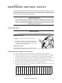
Accessing parts ..........................................................................................................................................................................21
Removing the printed circuit board ...........................................................................................................................................21
Replacing fuses..........................................................................................................................................................................22
Changing the XLR pin-out.........................................................................................................................................................22
Changing voltage and frequency settings ..................................................................................................................................22
Updating software......................................................................................................................................................................23
Changing lenses .........................................................................................................................................................................24
Replacing the lamp.....................................................................................................................................................................24
Optimizing lamp alignment .......................................................................................................................................................25
Installing the optional head shell safety wire.............................................................................................................................25
Maintenance schedule................................................................................................................................................................25
Cleaning.....................................................................................................................................................................................26
Lubrication.................................................................................................................................................................................26
section 7
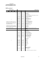
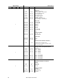
Appendices
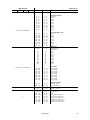
DMX protocol............................................................................................................................................................................27
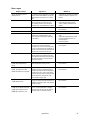
Messages....................................................................................................................................................................................31
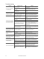
Troubleshooting ........................................................................................................................................................................32
Circuit board layout ...................................................................................................................................................................33
Specifications.............................................................................................................................................................................34

4
MAC 500/E User Manual
section 1
INTRODUCTION
Thank you for purchasing the MAC 500/E moving-head spotlight from Martin. Every detail of its construction and
programming is designed to make the MAC 500/Eextremelybright, quiet and reliable. With proper setup and mainte-
nance, it will provide years of trouble-free operation.
This manual covers the MAC 500 with magnetic ballast and the MAC 500 E with electronic ballast. “MAC 500/E”
refers to both models when describing common features and procedures. The features in software version 1.9 are
described. The latest MAC 500/E news and software is available from the Martin web site at http://www.martin.dk.
MAC 500/E safety information
WARNING!
This product is for professional use only. It is not for household use.
This product presents risks of lethal or severe injury due to fire and heat, electric shock, ultraviolet radiation, lamp
explosion, and falls. 5HD G WKLV PDQ XDO before powering or installing the fixture, follow the safety precautions listed
below and observe all warnings in this manual and printed on the fixture. If you have questions about how to operate
the fixture safely, please contact your Martin dealer or call the Martin 24-hour service hotline at +45 70 200 201.
To protect yourself and others from electric shock
• Disconnect the fixture from AC power before removing or installing the lamp, fuses, or any part, and when not in use.
• Always ground (earth) the fixture electrically.
• Use only a source of AC power that complies with local building and electrical codes and has both overload and
ground-fault protection.
• Do not expose the fixture to rain or moisture.
• Refer any service operation not described in this manual to a qualified technician.
To protect yourself and others from UV radiation and lamp explosion
• Never operate the fixture with missing or damaged lenses and/or covers.
• When replacing the lamp, allow the fixture to cool for at least 15 minutes before opening the fixture or removing
the lamp. Protect your hands and eyes with gloves and safety glasses.
• Do not stare directly into the light. Never look at an exposed lamp while it is lit.
• Replace the lamp before usage exceeds the maximum service life, or if the lamp is defective or worn out.
To protect yourself and others from burns and fire
• Never attempt to bypass the thermostatic switch or fuses. Always replace defective fuses with ones of the speci-
fied type and rating.
• Keep all combustible materials (for example fabric, wood, paper) at least 1.0 meter (39 inches) away from the
fixture. Keep flammable materials well away from the fixture.
• Do not illuminate surfaces within 1.0 meter (39 inches) of the fixture.
• Provide a minimum clearance of 0.1 meters (4 inches) around fans and air vents.
• Never place filters or other materials over the lens.
• The exterior of the fixture can reach temperatures up to 140° C (284° F). Allow the fixture to cool for at least 5
minutes before handling.
• Do not modify the fixture or install other than genuine Martin parts.
• Do not operate the fixture if the ambient temperature (Ta) exceeds 40° C (104° F).
To protect yourself and others from injury due to falls
• When suspending the fixture above ground level, verify that the structure can hold at least 10 times the weight of
all installed devices.
• Verify that all external covers and rigging hardware are securely fastened and use an approved means of second-
ary attachment such as a safety cable.
• Block access below the work area whenever installing or removing the fixture.
• Do not lift the fixture by its head.

5
Setup
section 2
SETUP
This section describes the steps required to prepare the MAC 500/E for operation.
Unpacking
The MAC 500/Epackage includes:
• 2 Fast-Lock clamp brackets
• 5-meter XLR-XLR control cable
• User manual
• 7 extra gobos
• 1 spare rotating gobo spring
The packing material is carefully designed to protect the fixture during shipment - always use it or a custom MAC 500/
600 flight case to transport the fixture.
1RWH0$&IOLJK WFDVHVSURGXFHGEHIRU H6HSWHPEHUDUHQRWGHHSHQRXJKIRUWKH0$&( These flight
cases can be identified by the outside measurements: 860 mm (34") from bottom to top, including wheels, on the out-
side. Suitable flight cases measure 894 mm (35.2") from bottom to top, including wheels.
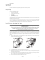
Installing or changing the lamp
WARNING!
Disconnect the fixture from AC power before proceeding. Always wear safety
goggles to protect your eyes and allow a hot lamp to cool for at least
15 minutes before removing it from the fixture.
The MAC 500/E is designed to work with the Philips MSR-575/2, Philips MSD-575, Osram HSD-575, or the Osram
HSR-575/2 discharge lamps. ,QVWDOOLQJDQ\RWKHUODPSPD\GDPDJHWKHIL[WXUHThe lamp holder is pre-adjusted at the
factory; precise alignment may be necessary due to slight variations between lamps. The procedure is described on
page 25.
1. The MAC 500/E must be cool and isolated from AC power. Remove the 2 screws holding the lamp
assembly. Gently remove the assembly.
2. If changing the lamp, remove the old lamp from the socket.
3. Holding the new lamp by its ceramic base (do not touch the glass), carefully insert it firmly and
squarely into the lamp socket.
4. Clean the glass bulb with the cloth supplied with the lamp, particularly if your fingers touch the
glass. A clean, lint-free cloth wetted with alcohol may also be used.
5. Re-insert the lamp assembly and replace the screws.

6
MAC 500/E User Manual
6. Before turning the lamp on, reset the RLAH and RLST counters. See “Readouts” on page 14.
Powering the fixture
WARNING!
For protection from dangerous electric shock, the fixture must be grounded
(earthed). The AC mains supply shall be fitted with a fuse or circuit breaker
and ground-fault protection.
Check voltage and frequency settings
7KHYROWDJHDQGIUHTXHQF\VHWWLQJVPXVWPDWFKWKHORFDO$&SRZHUVXSSO\ Operating at the incorrect setting can result
in poor light output, shortened lamp life, overheating and damage to the fixture. The settings are printed on the serial
number label on the bottom of the base: if the voltage does not match the local supply or the frequency (50/ 60 Hz) is
different, then the ballast and/or transformer must be rewired as described on page 22.
Install a plug on the power cord
You may need to install a cord cap that fits your supply on the power cable. Following the manufacturer’s instructions,
install an approved 3-prong grounding-type plug that fits your supply. Connect the wires to the pins as listed below.
The table shows some possible pin identification schemes; if the pins are not clearly identified, or if you have any
doubts about proper installation, consult a qualified electrician.
When ready to operate, connect the MAC 500/E directly to AC power.'RQR WFR QQHFWLWWR D GLPPHUV\VWHPG RLQJVR
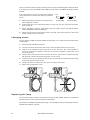
PD\GDPDJHWKHIL[WX UH To apply power, set the power switch on the base to the “I” position.
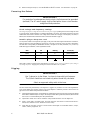
Rigging
WARNING!
Use 2 clamps to rig the fixture. Lock each clamp with both fasteners.
The 1/4-turn fasteners are locked only when turned fully clockwise.
Attach an approved safety cable to the base.
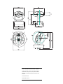
The MAC 500/E can be placed directly on the stage floor or rigged in any orientation on a truss. The integrated Fast-
Lock system enables quick and easy fastening of the clamp adapters in 4 different positions as shown below. See
page 35 for a list of suitable clamps available from Martin.
1. Verify that the rigging clamps (not included) are undamaged and can bear at least 10 times the weight
of the fixture. Bolt the clamps securely to the clamp brackets with a grade 8.8 (minimum) M12 bolt and
lock nut, or as recommended by the clamp manufacturer.
2. Tip the MAC 500/E on its side or install the clamps while the fixture is in the flight case.
3. Align a clamp with 2 mounting points. Insert the fasteners into the base and turn both levers a
full 1/4-turn clockwise to lock. Install the second clamp.
4. Verify that the structure can bear at least 10 times the weight of all installed fixtures, clamps,
cables, auxiliary equipment, etc.
Wire Pin Marking Screw (US)
brown live “L” yellow or brass
blue neutral “N” silver
yellow/green ground green

7
Setup
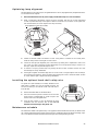
5. Working from a stable platform, hang the fixture on the truss. The front of the fixture is indicated
by the arrow on the base.
6. Install a safety wire that can bear at least 10 times the weight of the fixture. The attachment
point is designed to fit a caribiner clamp.
Never use the carrying handles for secondary attach-
ment.
7. Tighten the rigging clamps securely to the structure.
8. Verify that there are no combustible materials or surfaces to be illuminated within 1 meter of the
fixture, and that there are no flammable materials nearby.
IMPORTANT!
When rigging the fixture within 1 meter of other fixtures, avoid illuminating
one fixture with another. The intense light can melt plastic parts.
Connecting the serial link
Tips for building a serial link
1. Use shielded twisted-pair cable designed for RS-485 devices: standard microphone cable cannot
transmit DMX data reliably over long runs. For links up to 300 meters (1000 ft.) long, you can use 24
AWG, low capacitance, 85-150 ohm characteristic impedance, shielded cable with 1 or more twisted
pairs. For runs up to 500 meters (1640 ft.) use 22 AWG cable. Use an amplifier if the serial link
exceeds 500 meters.
2. Never use a “Y” connector to split the link. To split the serial link into branches use a splitter
such as the Martin 4-Channel Opto-Isolated RS-485 Splitter/Amplifier.
3. Do not overload the link. Up to 32 devices may be connected on a serial link.
4. Terminate the link by installing a termination plug in the output socket of the last fixture on the
link. The termination plug, which is simply a male XLR connector with a 120 ohm, 0.25 watt
resistor soldered between pins 2 and 3, “soaks up” the control signal so it does not reflect back
down the link and cause interference. If a splitter is used, terminate each branch of the link.
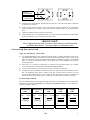
Connecting fixtures
The MAC 500/E has locking 3-pin data input and output sockets that can be configured for use with either DMX or
Martin Protocol controllers. 7K H GH IDXOWSLQRXWLVFRQILJXUHGWR WKH'0;VWDQGDUG , i.e., pin 1 to shield, pin 2
to signal (-) and pin 3 to signal (+).
safety wire
attachment point
arrow points to front
(neutral pan)
Phase-Reversing
Cable
Male Female
1
2
3
1
2
3
3-pin to 3-pin
Connections
P/N 11820006
Phase-Reversing
Cable
Male Female
1
2
3
1
2
3
4
5
3-pin to 5-pin
Connections
P/N 11820002
Phase-Reversing
Cable
Male Female
1
2
3
4
5
1
2
3
5-pin to 3-pin
Connections
P/N 11820003
Straight
Cable
Male Female
1
2
3
4
5
1
2
3
5-pin to 3-pin
Connections
P/N 11820005
Straight
Cable
Male Female
1
2
3
1
2
3
4
5
3-pin to 5-pin
Connections
P/N 11820004

8
MAC 500/E User Manual
1. Connect the controller’s data output to the MAC 500/E’s data input. For a
• DMX controller with 5-pin output: use a cable with 5-pin male and 3-pin female connectors such
as P/N 11820005. Pins 4 and 5 are not used.
• DMX controller with 3-pin output: use a cable with 3-pin male and female connectors such as the
one supplied.
• Martin RS-485 Protocol controller: use a phase-reversing cable, such as P/N 11820006, with 3-
pin male and female connectors or reconfigure the XLR output.
2. Continue the link: connect the output of the fixture closest to the controller to the input of the
next fixture. Use a phase-reversing cable when connecting a DMX-standard (pin 3 +) device to a
Martin-standard (pin 3 -) device.
3. Insert a male 120
Ω
XLR termination plug in the output of the last fixture on the link.

9
Operation
section 3
OPERATION
This section describes the MAC 500/E’s controllable effects and the options for customizing them for your application.
Option selection is described in the next section.
Martin RS-485 control
The MAC 500/E may be controlled with the Martin 3032 controller with version 2.04 or later software. To respond to
the controller, either the protocol setting (
PSET) must be set to Martin (MART) as described in the previous section,
or automatic protocol detection (
SPEC/AUTO) must be enabled. If automatic protocol detection is enabled, send a
dummy command and wait 1 second to allow the fixture to respond before sending real commands.
DMX-512 control
The MAC 500/E may be operated with USITT DMX512 controllers in 4 modes that combine tracking or tracking/vec-
tor movement with 8-bit or 16-bit pan/tilt resolution.
Tracking control
Tracking is available in all 4 DMX modes. With tracking control, the controller calculates the positions along the path
between an effect’s starting point and it’s ending point. It uses the fade time to calculate the change (delta) of each
update or refresh, which the fixture “tracks.” For smooth movement with any fade time, the MAC 500/E has a filter
algorithm that looks at several position updates (samples), and calculates the ideal speed.
This algorithm is adjustable to compensate for controllers that calculate position changes unevenly. In most cases the
default settings work well.
If movement is not satisfactory there are 2 parameters that can be adjusted. The first is the calculation method used and
is selected under
SPEC/TRAC/MOdE. MOd1, the default, calculates speed based on the absolute value of the
change in DMX; it is the best choice with controllers that calculate intermediate positions that are close to the line of
travel. MOd2 uses the real value of the DMX delta to calculate speed and is better if the intermediate positions stray
significantly from the line of travel.
The second parameter is the number of position updates used to calculate speed. The level is adjustable between 1 and
10 under SPEC/TRAC/CAL. Increasing the number of samples increases the distance over which speed is calcu-
lated, making movement smoother but less responsive to sudden changes.
The ideal settings for both parameters will vary from controller to controller: experiment for best results. The real
value algorithm (
MOd2) is recommended when using the MAC 500/E with the Martin Lighting Director system.
Vector control
With vector control, available in DMX modes 3 and 4, the fixture is given just 1 position - the end position - and a
speed, which is set on a separate channel. )RUVPRRWK PRYHPHQWWK HID GHWLPH PXVWEH VHW WR LHWK HHIIHFW³E XPSV´
RU³VQDSV´IURPRQHSRVLWLRQ WRWKHQH[W With controllers that do not have programmable fade times, vector control
provides a way to set speed. Because the end point and speed are known from the beginning, vector control results in
smooth movement regardless the fade time or the controller’s processing power.
The speed channels allow vector control to be turned off, resulting in tracking control. In addition, they offer a “black-
out speed,” described below, and overrides of the
PTSP (pan/tilt speed), MOdE (studio mode), and SCUT (short-
cuts) personality settings.
When blackout speed is enabled, effects move at full speed. The dimmer/shutter closes while the effects move to make
the transition invisible. Dimmer/shutter strobe and pulse effects, however, override the blackout command.
8-bit versus 16-bit pan/tilt resolution
With 8-bit pan/tilt resolution, the pan and tilt are divided into 256 equal increments. Finer position control and
smoother movement is provided in the 16-bit modes, which divide the full pan range into 32,768 increments and the
full tilt range into 45,567 increments.

10
MAC 500/E User Manual
Controllable effects
All moving effects are reset to a “home” position when the fixture is powered up. The fixture can also be reset via
DMX if DMX reset (
SPEC/dRES) is enabled. There is also a combination of DMX values that allows you to reset
the MAC 500/E even if this feature is disabled; see the DMX protocol for details.
An on-the-fly position correction system monitors the position of the color wheels, fixed-gobo wheel, and rotating
gobos. If an error is detected, the shutter closes and the effect is reset to its home position. Normal operation resumes
immediately thereafter. This feature can be disabled by setting effects feedback (
SPEC/EFFb) to OFF.
General operation may be optimized for speed or quietness with the studio mode setting (SPEC/MOdE). The menu
setting may be overridden via DMX using the effects speed channel in DMX modes 3 and 4.
Lamp
The MAC 500/E can be set to automatically strike the lamp within 90 seconds of being powered on by setting the
Automatic Lamp On (
SPEC/ALON) personality to ON. A delay determined by the fixture address prevents all
lamps from striking at the same time.
If Automatic Lamp On is set to off (default), the lamp remains off until a “lamp on” command is sent from the control-
ler. A peak of electric current that can be many times the operating current is drawn for an instant when striking the
lamp: striking many lamps at once may cause a voltage drop large enough to prevent lamps from striking or trip the
main circuit breaker. Avoid this by programming a “lamp on” sequence that strikes lamps one at a time at 5 second
intervals.
Power to the lamp can be turned off from the controller if the DMX Lamp Off (
SPEC/dLOF) feature is enabled.
There is also a combination of DMX values that allows you to turn off the lamp even if this feature is disabled; see the
DMX protocol. %H FDUHIXO: it is not possible to strike the lamp within 8 minutes of having switched it off. The MAC
500/E will store a “lamp on” command and strike the lamp automatically when the 8 minutes have elapsed.
With the MAC 500 E, lamp power falls to 400 watts for cooler operation and longer lamp life when the shutter is
closed for 10 seconds. Power instantly returns to full when the shutter opens. Reduced power mode can also be forced
- with the shutter open - by setting channel 1 to a DMX value from 73 to 79.
Pan and tilt
The moving head pans 440° and tilts 306°. Movement may be optimized for speed by setting the pan/tilt speed
(
PTSP) personality to FAST, or for smoothness by setting it to SLOW. The setting may be overridden on the speed
channel in vector mode. Setting the movement speed to “blackout” in vector mode causes the shutter to black out the
light while the mirror is moving. The pan and tilt channels (DMX) can be inverted and/or swapped for convenience
using the pan/tilt (
PATI) menu.
Color wheels
The MAC 500/E has 2 9-position-plus-open color wheels, yielding a total of 100 possible combinations. The 4 temper-
ature correction filters and 14 dichroic colors combine in 67 useful ways that can be called on 1 DMX channel. Both
wheels can be scrolled, allowing for split color effects, snapped to fixed positions, and continuously rotated in both
directions at different speeds. The 67 colors can be called randomly on DMX channel 4.
The Shortcuts (
SPEC/SCUT) setting determines whether the wheels take the shortest path to the next position or
turn in one direction only. The setting may be overridden on the speed channel in vector mode. Setting the color speed
to “blackout” in vector mode causes the shutter to black out the light while the wheels are moving.
Focus
The beam may be focused from 2 meters (6.5 feet) to infinity. The beam angle with the standard lenses is 17°. An
optional 23.5° wide-angle lens set is available as well. See “Accessories” on page 35.
Fixed (static) gobos
There are 2 operating modes available for the fixed-gobo wheel, which has 9 positions for metal gobos plus an open
position. In “fixed” mode (
SPEC/gMOd/FIX), the wheel steps between fixed positions and shakes at variable
speeds. In “scroll” mode (
SPEC/gMOd/SCRL), the wheel scrolls continuously, shakes at 1 speed, and rotates in
2 directions at variable speed.
Setting the fixed-gobo speed to “blackout” in vector mode causes the shutter to black out the light while the wheel
turns from one position to another.

11
Operation
The Shortcuts (SPEC/SCUT) setting determines whether the gobo wheel takes the shortest path to the next posi-
tion or turns in one direction only. The setting may be overridden on the speed channel in vector mode.
Rotating gobos
The MAC 500/E has 5 rotating positions for glass or metal gobos. Gobos may be rotated in both directions at varying
speeds or indexed to any position. The function and gobo are selected on channel 5 and the velocity or index position
are selected on channel 6. Setting the rotating-gobo speed to “blackout” in vector mode causes the shutter to black out
the light while the wheel turns from one position to another and, if indexing is selected, while the gobo rotates between
positions.
To change the gobos, see “Gobo orientation and positions” on page 17.
Iris
The iris diameter ranges from 100 to 15 percent open. There are 6 variable/random pulsating iris effects callable on
channel 9. These can be disabled by switching DMX Macros (
SPEC/dMAC) off. The iris reflection reduction set-
ting (
SPEC/IRR) closes the iris slightly from full open to eliminate a halo effect seen in very early units.
Rotating prism / variable frost
The 3-facet prism can rotate in both directions at varying speeds. There are 8 preprogrammed macros that combine the
prism with rotating gobos on channel 10. These can be disabled by switching DMX Macros (
SPEC/dMAC) off.
Setting the prism speed to “blackout” in vector mode causes the shutter to black out the light while the prism moves in
and out.
An optional frost filter may be installed in place of the rotating prism to provide a variable frost effect. If the frost filter
is installed, the fixture type personality (
SPEC / FTYP) must be set to “FROS” to enable the frost variation of the
protocol.
Dimmer / shutter
The mechanical dimmer/shutter system provides smooth, high-resolution 100 percent dimming, “instant” open and
blackout, random and variable strobe effects up to 23 Hz, and random and variable pulses in which the dimmer snaps
open and slowly dims or snaps closed and slowly opens. The pulse and random strobe effects can be disabled by
switching DMX Macros (
SPEC/dMAC) off.
The Dimmer Mode (SPEC/dMOd) setting allows you to select between linear or simulated tungsten fade curves.
The fade time must be 0 to simulate tungsten dimming.

12
MAC 500/E User Manual
section 4
CONTROL PANEL
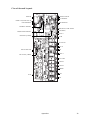
The 4-digit LED control panel on the front of the MAC 500/E allows you to set the address and personalities, read
lamp hours and other information, calibrate effects, control the fixture manually, and run stand-alone tests and demo
programs. Most of these functions may be performed remotely via the serial link with the MPBB1 Uploader
The display can be flipped for easy reading by pressing the [↑] and [↓]keys simultaneously. The intensity is adjustable
and the display can be set to go out 2 minutes after the last key-press.
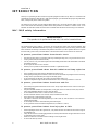
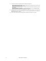
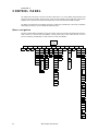
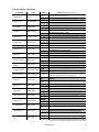
Menu navigation
The DMX or Martin address, depending on the protocol setting, and any error messages are displayed when the MAC
500/E is turned on. To enter the menu, press [MENU]. Use the [↑] and [↓]keys to move within the menu. To select a
function or submenu, press[ENTER]. To escape a function or menu, press [MENU].
dAdr
MAdr
TIME
AdJ CAL PATI VER
PSET
MAN dMXL PTSP SPEC
dEMO
Address/
Messages
Po H
RPoH
LA H
RLAH
LSTR
RLST
RST
L ON
LoFF
HEAd
PATI
P OF
T OF
C1OF
C2OF
RGOF
FGOF
d OF
SWAP
PINV
TINV
RST
L ON
SHUT
dIM
COL1
COL2
LoFF
Fgob
Rgob
IRIS
PRIS/
PAN
TILT
FOCU
FROS
STCO
SHUT
....
E SP
CPU
FEbA
dISP
FTYP
dISP
dLOF
dRES
ALON
FEbA
dINT
dFOF
UPLd
PCbT
AUTO
SCUT
IRR
dMAC
MOdE
FTST
dIM
COL1
COL2
Fgob
Rgob
FOCU
IRIS
PRIS
DEM1
PAN
TILT
FOCU
SEQ
DEM2
MINP
MAXP
MINT
MAXT
FOCU
SEQ
dFSE
FACT
CUS1
CUS2
CUS3
TEMP
bASE
HEAd
TSEQ
dMOd
EFFb
TRAC
MOdE
CAL
gMOd
FIX
SCRL
FOOF

13
Control Panel
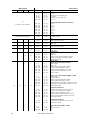
Personality settings
* Setting may be overridden via DMX. See the protocol for details.
Personality Path Options Effect (Default settings shaded.)
Pan/tilt speed PTSP
FAST
Optimize movement for speed*
SLOW
Optimize movement for smoothness*
Pan/tilt swap PATI/SWAP
ON
Map DMX pan control to tilt channel and vice versa
OFF
Normal pan and tilt control
Pan inverse PATI/PINV
ON
Reverse DMX pan control, right left
OFF
Normal pan control, left right
Tilt inverse PATI/TINV
ON
Reverse DMX tilt control, down up
OFF
Normal tilt control, up down
Fixture type SPEC/FTYP
PRIS
Operate with rotating prism
FROS
Operate with optional variable frost
Display on/off SPEC/dISP
ON
Display stays on
OFF
Display goes out 2 minutes after last key press
Display intensity SPEC/dINT
10-100
Adjust display intensity
DMX lamp off SPEC/dLOF
ON
Enable DMX lamp off command
OFF
Disable DMX lamp off command*
DMX reset SPEC/dRES
ON
Enable DMX reset command
OFF
Disable DMX reset command*
Automatic lamp on SPEC/ALON
ON
Lamp strikes automatically within 90 seconds of power on
OFF
Strike lamp from controller
Automatic protocol
detection
SPEC/AUTO
ON
Enable automatic protocol detection
OFF
Disable automatic protocol detection
Tracking algorithm SPEC/TRAC/MOdE
MOd1
Absolute delta value algorithm (for most controllers)
MOd2
Real delta value algorithm
Tracking samples SPEC/TRAC/CAL
1-10
Tracking mode sample level - default is 6. Higher levels give
smoother movement but slower acceleration.
Shortcuts SPEC/SCUT
ON
Color wheels and fixed-gobo wheel turn the shortest
direction*
OFF
Wheels turn same direction*
DMX macros SPEC/dMAC
ON
Enable DMX-selectable macros and pulsating effects
OFF
Disable DMX-selectable macros and pulsating effects
Studio mode SPEC/MOdE
NORM
Optimize effects for speed
STUd
Optimize effects for silence
Fixed gobo mode SPEC/gMOd
FIX
Static gobo wheel steps between full positions
SCRL
Static gobo wheel scrolls continuously
Dimmer mode SPEC/dMOd
NORM
Normal dimming curve
TUNG
Simulated tungsten dimming curve
Pan/tilt feedback SPEC/FEbA
ON
Enable pan/tilt position correction system
OFF
Disable pan/tilt feedback. Setting not saved
Effects feedback SPEC/EFFb
ON
Enable feedback from magnetic sensors on color
wheels, fixed-gobo wheel, and rotating-gobo index
OFF
Disable feedback from magnetic sensors
Iris reflection reduc-
tion
SPEC/IRR
ON
Iris opens 95 percent. Recommended for early units only
OFF
Iris opens 100 percent

14
MAC 500/E User Manual
Address and protocol selection
One of the operating modes shown below must be selected. Factors to consider when selecting a mode will depend on
your controller and are discussed in the previous section. Maximum flexibility is provided in mode 4.
Each fixture must be assigned its own channels to receive instructions from the controller. The address, also known as
the start channel, is the first channel used. Addresses are independent of the physical link: they may be set in any con-
venient order. Two MAC 500/Es may share the same address; however, they will receive the same instructions and
independent control will not be possible.
1. Apply power to the MAC 500/E.
2. If you want to change settings while the MAC 500/E is in a flight case, push [MENU] and
[ENTER] simultaneously to disable pan and tilt reset. The partial reset procedure can take 2 - 3
minutes and will result in error messages being displayed; this is not a fault with the fixture.
3. Press the [MENU] key and then press [↑] or [↓] until the display shows
PSET. Press [ENTER].
4. Press [↑] or [↓] until the desired protocol (Martin, or DMX mode 1, 2, 3, or 4) appears on the dis-
play. Press [ENTER] to confirm.
5. Press [↑] or [↓] until the display shows
dAdr (to set a DMX address) or MAdr (to set a Martin
address). Press [ENTER] to confirm.
6. Press [↑] or [↓] to select the address. Press [ENTER] to confirm.
7. Press [MENU] to return to the main menu. The address is displayed.
Readouts
Usage readouts (TIME)
Read the total number of power-on hours (Po H), power-on hours since last reset (RPoH), total lamp hours (LA H),
lamp hours since last reset (
RLAH), total number of lamp strikes (LSTR), and the number of lamp strikes since last
reset (
RLST).
The resettable counters may be used to track overall usage and lamp life. To reset to zero, display the readout and then
press [↑] for 5 seconds.
DMX value readouts (dMXL)
Read the DMX start code (STCO) and DMX values received for each effect. This is an easy way to check that the
DMX start code is 0 and that the fixture is receiving the expected DMX values.
Software version readouts (VER)
Read the version number of the CPU software (CPU), feedback circuit software (FeBA), and display module soft-
ware (
dISP). The CPU software version is also displayed for a moment at power up.
Temperature readouts (SPEC/TEMP)
Read temperature in the base (bASE) and head (HEAd) in Celsius. Temperatures below 25° C are shown as -25;
temperatures above 100° C are shown as
+100.
Thetemperature sensors are calibrated at the factory and adjustment should not be necessary. The following procedure
calibrates the sensors if they give no or faulty readings.
1. Allow the unit to cool to room temperature (powered off for at least 4 hours).
2. Measure the room temperature in Celsius. (To convert F° to C°, subtract 32° and then multiply
by 0.555.)
3. Power up the unit and allow it to reset.
Mode Martin DMX 1 DMX 2 DMX 3 DMX 4
Movement speed Vector Tracking Tracking and/or Vector
Pan/tilt resolution 16 bit 8 bit 16 bit 8 bit 16 bit
Channels required 2 12 14 14 16

15
Control Panel
4. Press the [MENU] and [↓] keys at the same time and hold them for 3 seconds until “25” shows in
the display.
5. Press the [↑] and [↓] keys until the display shows the temperature measured.
6. Press [ENTER] to save the setting.
Manual control
Manual control (MAN)
The manual control menu permits you to do the following without a controller:
• reset the fixture (RST)
• turn the lamp on and off (
L ON, LoFF)
• open, close, and strobe the shutter at 3 speeds (
SHUT)
• control the dimmer (
dIM)
• move the color wheels to each position and scroll them at 3 speeds (
COL1, COL2)
• move the fixed-gobo wheel to each position (
Fgob)
• move the rotating-gobo wheel to each position and rotate the gobos at 3 speeds (
Rgob)
• control the focus (
FOCU)
• control the iris (
IRIS)
• insert and rotate the prism (
PRIS) at 3 speeds, or, if a frost filter is installed, vary the frost (FROS)
• control pan and tilt (
PAN, TILT)
Adjustment (AdJ)
The adjustment menu provides manual control for making mechanical adjustments. These should be performed by a
qualified technician. The menu provides functions to reset the fixture (
RST), turn on and off the lamp (L ON,
LoFF), control all effects in the head (HEAd), and move the head to the home and extreme positions (PATI). The
HEAd submenu allows the technician to:
• open, close, and strobe the dimmer/shutter (
dIM)
• move the color and gobo wheels through their positions (
COL1, COL2, Fgob, Rgob)
• move the focus lens to its extreme positions (
FOCU)
• open and close the iris (
IRIS)
• insert and rotate the prism (
PRIS)
Stand-alone sequences
Demonstration programs (dEMO)
This menu offers 2 preprogrammed demonstrations. Demo 1 shows each effect individually and in combination with
others at a set home position. Demo 2 pans and tilts within a defined area and shows various effect combinations.
Before running demo 1, set the pan/tilt position (
PAN, TILT) to a good location for viewing the effects and then
focus (
FOCU) the beam. Select SEQ to run the demo. Demo 2 is similar but instead of defining a home position, you
define an area such as a screen or wall by setting the minimum and maximum pan and tilt positions (
MINP, MAXP,
MINT, MAXT). Focus the beam in the center of the area.
Test sequences
7HVWVHTXHQFHTSEQRun a general test of all effects.
3ULQWHGFLUFXLWERD UG WHVW
SPECPCBT This menu provides 4 tests of the circuit board for service use: TI,
T2, T3, and LEd.
)DFWRU\WHVWSPECFTST: This menu provides an effects test (ETST), a movement test (MTST), and a sensor
test (
STST) used for quality control. The sensor test includes programs for testing sensors on the color and gobo
wheels (
COL1, COL2, Rgob, and Fgob).

16
MAC 500/E User Manual
Utilities
Calibration (CAL)
The calibration menu allows you to adjust the effects to achieve total uniformity between fixtures: it is not a substitute
for mechanical adjustment. Select dimmer/shutter (
d OF), color wheels (C1OF, C2OF), rotating-gobo wheel
(
RGOF), fixed-gobo wheel (FGOF), or focus (FOOF) and adjust the effect’s offset with the arrow keys. Offsets are
adjustable from 1 to 255 for all effects except the fixed-gobo wheel, which is adjustable from 127 to 129. Press
[ENTER] to save the calibration.
Reset default offsets (SPEC/dFOF)
Reset all calibrations to their factory defaults. Select dFOF and press [ENTER] when SURE is displayed.
Reset default personality settings (SPEC/dFSE/FACT)
Return all personality settings (not calibrations) to their factory defaults. Select FACT and press [ENTER] when
LOAD is displayed.
Custom configurations (SPEC/dFSE/CUS1, CUS2, CUS3)
Save and load 3 sets of custom configurations. To save a custom configuration, adjust the settings as desired, go to
CUS1, CUS2, or CUS3 and press [ENTER] when SAVE is displayed. To load a custom setting, select it and
press [ENTER] when
LOAD is displayed.
Upload mode (UPLd)
Upload mode prepares the MAC 500/E to receive control software. It is normally engaged automatically when using
the MPBB1 or MP-2 uploaders In certain circumstances, however, you may have to set upload mode manually as
described under “Updating software” on page 23.

17
Gobos and Color Filters
section 5
GOBOS AND COLOR FILTERS
The MAC 500/E has 5 rotating positions for glass or metal gobos, 9 static positions for metal gobos, and 9 positions
for interchangeable dichroic glass color filters in special holders. This section describes how to replace these items.
Gobo specifications
For best results, MAC 500/E gobos should meet the following specifications.
Glass gobos
• Coating: ................................................................................................. dichroic or enhanced aluminum
• Material: ........................................................................................high temperature, Borofloat or better
• Thickness:............................................................................................................................. 1.1- 4.0 mm
• Outside diameter:........................................................................................................27.9 + 0 /- 0.3 mm
• Maximum image diameter:............................................................................................................23 mm
Glass gobos should be made with the artwork reversed on the coated side. This orientation gives the best focus but is
not critical. We do not recommend using chrome-coated glass gobos in the MAC 500/E. They absorb more heat than
enhanced aluminum gobos and are likely to break or oxidize. If used, their lifetime can be extended somewhat by
inserting the gobos with the coated side towards the lamp.
Metal gobos
• Material: ...................................................................................................................................aluminum
• Thickness:.....................................................................................................................................0.5 mm
• Outside diameter:........................................................................................................27.9 + 0 /- 0.3 mm
• Maximum image diameter:............................................................................................................23 mm
*Steel metal gobos may give acceptable short term performance. Gobos less than 0.5 mm thick may need to be secured
with a drop of high temperature silicone adhesive when used in the static positions.
Gobo orientation and positions
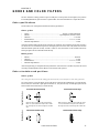
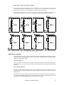
Glass gobos
1RWH*ODVVJRERVPD\EHXVHGLQWKHURWDWLQJJRERZKHHORQO\7KH\DUHWRRWKLFNIRUXVHLQWKHVWDWLFJRERZKHHO
For correct projection of text and images, the side with the true image must be installed facing in, towards the lamp.
For best focus, the coated side of glass gobos should face out, away from the lamp. Textured glass gobos must be
inserted with the smooth side facing in, towards the lamp.
Coated Glass Gobos
When an object is held up to the uncoated side,
there is a space between the object and its reflec-
tion. The edge can be seen through the uncoated
side.
Coated side towards stageUncoated side towards lamp
When an object is held up to the coated side, there
is no space between the object and its reflection.
The edge cannot be seen through the coated side.
Textured side towards stageSmooth side towards lamp
Textured Gobos

18
MAC 500/E User Manual
Metal and image gobos
The metal gobos supplied with the MAC 500/E may be used in either wheel. They are black on one side to reduce
reflections; the black side must face out, away from the lamp. For correct projection of text and images, the side with
the true image must be installed facing in, towards the lamp.
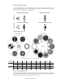
Default gobo layout
Loose rotating gobo fix
If a rotating gobo becomes a little loose and spins in the holder (losing its indexed position), remove the gobo, apply
three dots of red, high-temperature silicone (P/N 37001201) in the holder recess, and let the silicone harden before
replacing the gobo. The additional friction will keep the gobo from spinning.
Metal Gobos
Reflective side towards lamp
Bl
ac
k
s
id
e
t
owar
d
s s
t
age
Image Gobos
Correct image towards lamp Reversed image towards stage
Position123456789
Rotating
gobo wheel
Triangle Bar Fan Thin bars Grid ball - - - -
43076004 43076002 43076006 43076005 43076011
Static gobo
wheel
Cone Dots Lotus Bricks Clouds Machine Bamboo Threads Pling
43076012 43076013 43076014 43076015 43076016 43076017 43076018 43076019 43076020
R
otat
i
ng-go
b
o w
h
ee
lFi
xe
d
-go
b
o w
h
ee
l
Gobo wheels as seen from front, in open position.

19
Gobos and Color Filters
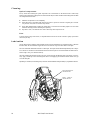
Changing rotating gobos
WARNING!
Disconnect the fixture from AC power before removing any cover.
Without tools
1. Remove the top head cover as described under “Accessing parts” on page 21.
2. Turn the gobo wheel until the easiest access to the desired gobo position is obtained. Turn the
color wheel until the open position is over the gobo position.
3. Tilt the head so the lens points down. Push the gobo and retaining spring out of the back of the
holder. Avoid letting the spring and gobo fall into the head.
4. Insert the new gobo. See below for proper gobo orientation.
5. Insert the retaining spring with the bend facing out, away from the gobo. Working through the
open position in the color wheel, push the gobo and spring all the way down into the gobo
holder.
With needlenose pliers
With a little practice, this method is faster than the above method.
1. Turn the gobo wheel until the easiest access to the desired gobo position is obtained. Turn the color
wheel until the open position is over the gobo position.
2. Turn the gobo holder until you can see the tab on the holder retaining spring.
3. Grip the tab on the retaining spring with a pair of small (needlenose) pliers. Place your index fin-
ger over the spring to prevent it from falling into the fixture. Open the spring and remove it from
the gobo holder.
4. Remove the gobo holder from the bearing by pulling it forwards towards the lens.
5. Push the gobo and gobo retaining spring out of the holder.
6. Insert the new gobo. See below for proper gobo orientation. Insert the gobo retaining spring.
The bend in the spring faces out, away from the gobo. Push the gobo and spring all the way
down into the gobo holder.
7. Replace the gobo holder in the bearing. Do not force the holder into the bearing: it will go in eas-
ily if it is installed straight.
8. Grip the retaining ring by the tab with the pliers. Place your thumb on the back of the gobo
holder to press it all the way down in the bearing and use your index finger to hold the other end
of the spring on the holder. Open the spring and place it in the groove.
Changing static gobos
1. Remove the top head cover as described under “Accessing parts” on page 21.
2. Manually turn the fixed-gobo wheel until the desired gobo is accessible. Turn the color wheel
until the open position aligns with the gobo.
3. Using your forefinger, release the gobo by pushing in back slightly towards the lamp. Grasp the
gobo by bringing your thumb to the back, and slide the gobo out of the wheel.
4. To place a gobo in the wheel, first turn the gobo so that the black side faces the front and the
reflective side faces the lamp. Then, using your thumb and forefinger, slide the gobo into posi-
tion between the spring clips on the back of the gobo wheel.
5. Verify that the gobo is fully seated in the recessed groove by gently sliding it back and forth. If
the gobo is seated correctly, you will be able to feel a tiny amount of movement.

20
MAC 500/E User Manual
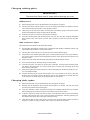
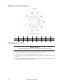
Default color filter positions
Changing color filters
WARNING!
Disconnect the fixture from AC power before removing any cover.
1. Remove the top head cover as described under “Accessing parts” on page 21.
2. Manually turn the color wheel until the desired filter is accessible.
3. Using a soft cloth or gloves, gently tilt the outside edge of the filter towards the front lens and
remove.
4. To place a filter in the wheel, insert the plastic holder between the spring clip - with the protrud-
ing tab facing the lamp - until it snaps into place.
123456789
Blue 111 Red 301 Magenta 507 Green 202 Yellow 604 Purple 502 Blue 101 Pink 312 Cyan 401
62327015 62327021 62327023 62327018 62327019 62327025 62327016 62327022 62327017
Color wheel 1
Wheel as seen from front, in open position.
La pagina si sta caricando...
La pagina si sta caricando...
La pagina si sta caricando...
La pagina si sta caricando...
La pagina si sta caricando...
La pagina si sta caricando...
La pagina si sta caricando...
La pagina si sta caricando...
La pagina si sta caricando...
La pagina si sta caricando...
La pagina si sta caricando...
La pagina si sta caricando...
La pagina si sta caricando...
La pagina si sta caricando...
La pagina si sta caricando...
La pagina si sta caricando...
La pagina si sta caricando...
La pagina si sta caricando...
-
 1
1
-
 2
2
-
 3
3
-
 4
4
-
 5
5
-
 6
6
-
 7
7
-
 8
8
-
 9
9
-
 10
10
-
 11
11
-
 12
12
-
 13
13
-
 14
14
-
 15
15
-
 16
16
-
 17
17
-
 18
18
-
 19
19
-
 20
20
-
 21
21
-
 22
22
-
 23
23
-
 24
24
-
 25
25
-
 26
26
-
 27
27
-
 28
28
-
 29
29
-
 30
30
-
 31
31
-
 32
32
-
 33
33
-
 34
34
-
 35
35
-
 36
36
-
 37
37
-
 38
38


Martin MAC 500E Manuale utente
- Categoria
- Stroboscopi
- Tipo
- Manuale utente
in altre lingue
- English: Martin MAC 500E User manual
Documenti correlati
Altri documenti
-
 DTS XR10 SPOT Manuale utente
-
 DTS XR700 SPOT Manuale utente
-
 DTS 03.MS014.EBLFP Manuale utente
-
 DTS XR2000 SPOT CMY Manuale utente
-
 DTS Synergy 5 Spot Manuale utente
-
SGM IDEA SPOT 700 Manuale utente
-
 DTS JACK Manuale utente
-
ProLights 240W moving spot Manuale utente
-
 DTS EVO Manuale utente
-


