
EW00AB*02*: Access Point, comunicazione con Terminali/Sonde wireless del sistema Easy Way / Access Point, communication with EasyWay system wireless Terminals/Sensors
+050001310 - rel. 1.0 date 13.09.2007
Caratteristiche generali
L’Access Point, controllo elettronico che fa parte del sistema “Easy Way” permette la comunicazione tra
dispositivi in protocollo CAREL (pCO sistema, plantVisor) e terminali (EW**T*), sensori (EW**S*) o
altri ripetitori (EW**R*) wireless.
Il prodotto può essere commercializzato in tutti i paesi della Comunità Europea.
Per tutti gli altri paesi si verifichi la Normativa vigente in relazione alle caratteristiche radio.
Installazione
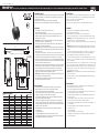
• Fissare alla parete L’Access Point con il pressacavo verso il basso;
• collegare la rete RS485 al morsetto (4);
• avvitare l’antenna nell’apposito alloggio (2), orientarla in modo verticale rispetto al pavimento;
• collegare l’alimentazione al morsetto (1), facendo attenzione alle polarità indicate, nel caso di
alimentazione a tensione continua;
ATTENZIONE: Se si condivide la stessa alimentazione per più macchine, connettere lo stesso filo
del trasformatore sul morsetto “–“ dell’alimentazione (1);
• Il dip switch (3) seleziona l’indirizzo per il supervisore della macchina. Si veda la tabella 1 per la
scelta dell’indirizzo e si imposti l’indirizzo desiderato;
ATTENZIONE: è possibile impostare l’indirizzo soltanto in questa fase. Qualsiasi modifica, quando è
impostato il canale, verrà ignorata. È possibile modificare l’indirizzo solo dopo aver re-inizializzato il
dispositivo (stato F Tab. 2);
• Acceso lo strumento si prema il tasto T1, si accendono L1 e L2, lo strumento sta ricercando un
canale libero per la comunicazione. Attendere circa una decina di secondi e L1 inizia a lampeggiare,
lo strumento è configurato ed è pronto all’accettazione di nuovi terminali, sensori o ripetitori;
• Per associare un nuovo strumento si prema il tasto T1 i 3 led iniziano a lampeggiare simultaneamente,
l’Access Point è pronto per l’associazione di nuovi strumenti. Si consulti la documentazione degli altri
strumenti per conoscerne le modalità di associazione;
• quando viene associato un nuovo strumento come terminale o sensore i led si accendono in sequenza,
questo significa che l’associazione è andata a buon fine e lo strumento è associato all’Access Point;
• Se i led non lampeggiano come indicato nelle fasi precedenti, oppure si sono eseguite delle
operazioni errate, si prema il tasto T1 per qualche secondo e l’Access Point viene re-inizializzato.
A questo punto si ripetano le operazioni descritte nelle fasi precedenti.
ATTENZIONE: Se lo strumento viene re-inizializzato tutti gli strumenti associati a lui vengono persi e
sarà necessaria una nuova annessione degli strumenti.
• Copia della dichiarazione di conformità può essere trovata al seguente indirizzo: http://www.carel.
com/carelcom/web/eng/mercati/condizionamento.tsp
Avvertenze generali
• Fissare il terminale nel posto desiderato tenendo in considerazione che si sta installando
un’apparecchiatura radio per cui sono necessari i seguenti semplici accorgimenti:
- Evitare di racchiudere l’apparecchiatura tra due pareti metalliche;
- L’efficienza della trasmissione radio si riduce in presenza di ostacoli o in presenza di scaffalature
metalliche, o quant’altro possa ostacolare la ricezione dei segnali radio;
- Se il prodotto viene installato a muro, fissarlo su una parete murale piuttosto di una metallica,
questo permette una maggiore portata del segnale;
- Si tenga conto che la migliore posizione dell’Access Point è quella in cui è “visibile” dagli altri
dispositivi. Si consiglia quindi di posizionarlo in modo tale da ridurre il più possibile gli ostacoli;
- Come qualsiasi apparecchiatura radio, evitare di fissare l’Access Point in vicinanza di altri apparecchi
elettronici in modo da evitare interferenze;
• Evitare l’installazione dello strumento in ambienti che presentino le seguenti caratteristiche:
- forti vibrazioni o urti;
- esposizione a getti d’acqua;
- esposizione all’irraggiamento solare diretto e agli agenti atmosferici in genere;
- Qualora l’apparecchio venisse utilizzato in un modo non specificato dal costruttore, le protezioni
previste dall’apparecchio potrebbero essere compromesse.
94
102
40
108
190
13
DIP: 1 2 3 4
+ +
G
- -
1 4
3
2
Rx- Rx+ GND
L1
L2 L3
50
70
Fori di fissaggio
Mounting holes
Dimensioni (mm)/Dimensions (mm)
Fig. 1
Indirizzi per il supervisore
DIP 1 DIP 2 DIP 3 DIP 4 Indirizzo seriale
Off Off Off Off non valido
On Off Off Off 1
Off On Off Off 2
On On Off Off 3
Off Off On Off 4
On Off On Off 5
Off On On Off 6
On On On Off 7
Off Off Off On 8
On Off Off On 9
Off On Off On 10
On On Off On 11
Off Off On On 12
On Off On On 13
Off On On On 14
On On On On 15
Tab. 1
General features
The Access Point, an electronic controller that is part of the “Easy Way” system, ensures communi-
cation between devices with the CAREL protocol (pCO sistema, PlantVisor) and wireless terminals
(EW**T*), sensors (EW**S*) or other repeaters (EW**R*).
The product may be sold in all EU countries.
For all other countries, check the legislation in force with regards to the radio specifications.
Installation
• Fasten the Access Point to the wall with the cable gland facing downwards;
• connect the RS485 network to terminal (4);
• tighten the antenna in the special housing (2), position it vertically to the floor;
• connect the power supply to terminal (1), ensuring the polarity indicated for DC power supply;
IMPORTANT: If the same power supply is shared by more than one unit, connect the same wire
from the transformer to the “–“ terminal of the power supply (1);
• The dipswitch (3) selects the unit supervisor address. See Table 1 for the selection and setting of the
address;
IMPORTANT: the address can only be set at this time. Any changes, when the channel has been
set, will be ignored. The address can only be changed after having re-initialised the device (status
F, Table 2);
• Once the device has been switched on, press button T1; L1 and L2 will come on, the device sear
ches for a free communication channel. Wait around ten seconds, then L1 starts flashing, the
device is configured and is ready to accept new terminals, sensors or repeaters;
• To connect a new instrument, press button T1; the 3 LEDs start flashing together, the Access Point is
ready for the connection of new instruments. See documents on the other instruments for details on
the connection procedure;
• when a new instrument (terminal or sensor) is connected, the LEDs come on in sequence, meaning
the connection procedure has been successful and the instrument is connected to the Access Point;
• If the LEDs do not flash as described in the previous points, or incorrect operations have been per
formed, press button T1 for a few seconds to re-initialise the Access Point. Then repeat the opera
tions described in the previous points.
IMPORTANT: If the device is re-initialised, all the connections will be lost and the instruments will
need to be connected again.
• A copy of the declaration of conformity is available at http://www.carel.com/carelcom/web/eng/
mercati/condizionamento.tsp
General warnings
• Fasten the unit in the desired position, considering that as the device being installed is a radio
device, the following simple rules must be observed:
- Avoid enclosing the appliance between two metal walls;
- The efficiency of radio transmission is reduced when there are obstacles, metal shelving or other
objects that may block the reception of the radio signals;
- If the product is wall-mounted, fasten it to a masonry wall rather than a metal wall, to improve
the range of the signal;
- Remember that the best position for the Access Point is one where it is “visible” to the other
devices. It should be positioned in such a way as to minimise any obstacles;
- Like all radio equipment, avoid installing the Access Point near other electronic appliances, so as
to avoid interference;
• Do not install the instruments in environments with the following characteristics:
- strong vibrations or knocks;
- exposure to water sprays;
- exposure to direct sunlight or the elements in general;
- If the appliance is used in a way that is not described by the manufacturer, the specified level of
protection may be affected.

+050001310 - rel. 1.0 date 13.09.2007
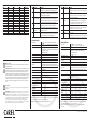
Meaning of the LEDs
Status Status of the LED MEANING
A L1 always on The device has been switched on for the first time or has been
re-initialised. Press button T1 to configure the channel and make it
operational.
B L1 and L2 always on The device is searching for the best transmission channel. Wait 10
seconds for the Access Point to end the search procedure and be
ready to accept new instruments.
C L1 Flashing
(operation)
The Access Point is operating and is communicating with the
connected instruments (terminals or sensors), sending data to the
supervisor. During communication with the instruments, L2 and L3
come on briefly; this should be considered normal.
D L1, L2 and L3 flashing The device is accepting new instruments. These instruments need to
be configured for connection to the Access Point. See the documents
on the instruments for the corresponding settings.
E L1 L2 and L3 flashing
in sequence
A new instrument has been recognised and has been connected to
the Access Point.
F L1 L2 L3 always on T1 has been pressed for 6 seconds and the Access Point will be
re-initialised. All the connected terminals, sensors or repeaters have
been cancelled and the device is ready to be reconfigured (Status A).
Tab. 2
Technical specifications
Power supply 24 V ±10 % (class 2 from distribution line)
24 V ±10 % -15 % 2 VA (class 2 safety transformer)
Power input 1 VA
Radio frequency specifications Frequency: selectable, from 2405 to 2480 MHz (by parameter
or automatic, see the table of supervisor parameters)
Power transmitted: 0 dBm
Wireless protocol: ZigBee
RS485 transmission speed 19200 Kb/s
CAREL protocol conformity Ver. 3 and higher
Max. no. of instruments that can
be connected
24 sensors/terminals; 8 repeaters
Operating conditions 0T50°C, <80% RH non-condensing
Storage conditions -20T70°C, <80% RH non-condensing
Connections - screw terminals for
power supply
-Power supply terminal: removable cables max size 1.5 mm²
-LAN 485 communication terminal: removable cables max size
1.5 mm² (use shielded cable with shield connected to GND)
Type of cable Shielded cable, max length 1000 m (RS485), 100 m (Power
supply)
Assembly wall-mounted by screws
Display/Configuration Read and write parameters via RS485 with CAREL master
protocol
Index of protection IP55 (Note 1)
Classification according to protec-
tion against electric shock
can be integrated in class 1 and 2 equipment
Environmental pollution normal
PTI of insulating materials 250V
Period of stress across the
insulating parts
Long
Category of resistance to heat
and fire
category D (box and cover)
Immunity against voltage surges category 2
Software class and structure Class A
Disposal observe local legislation for the disposal of electrical material
Tab. 3
Note 1: The index of protection is maintained only if a single cable is used for power and RS485
communication with an outside cross-section of less than 8 mm.
Note 2: for further information (list of supervisor models,...) see the corresponding manual
+030220840.
Supervisor addresses
DIP 1 DIP 2 DIP 3 DIP 4 Serial address
Off Off Off Off not valid
On Off Off Off 1
Off On Off Off 2
On On Off Off 3
Off Off On Off 4
On Off On Off 5
Off On On Off 6
On On On Off 7
Off Off Off On 8
On Off Off On 9
Off On Off On 10
On On Off On 11
Off Off On On 12
On Off On On 13
Off On On On 14
On On On On 15
Tab. 1
Significato dei led
Stato Stato dei LED SIGNIFICATO
A L1 sempre acceso Lo strumento è acceso per la prima volta oppure è stato re-inizializzato.
Premere il tasto T1 per configurare il canale e renderlo operativo.
B L1 e L2 sempre accesi Lo strumento sta ricercando il migliore canale di trasmissione.
Attendere un tempo di 10s perché l’Access Point concluda la ricerca e
sia pronto ad accettare nuovi strumenti.
C L1 Lampeggiante
(funzionam. operativo)
L’Access Point è operativo e sta comunicando con gli strumenti
(terminali o sensori) ad esso associati e invia i dati al supervisore.
Durante la comunicazione con gli strumenti L2 e L3 si accendono per
qualche istante, questo comportamento è da ritenersi normale.
D L1, L2 e L3 lampeg-
gianti
Lo strumento accetta nuovi strumenti. E’ necessario predisporre
anche questi per l’associazione con l’Access Point. Si veda la
documentazione relativa agli strumenti per la loro impostazione.
E L1 L2 e L3 lampeggianti
in sequenza
Visualizza che un nuovo strumento è stato riconosciuto ed è stato
associato all’Access Point.
F L1 L2 L3 sempre accesi Si è premuto T1 per un tempo di 6S e l’Access Point sta per essere re-
inizializzato. Tutti i terminali sensori o ripetitori ad esso associati sono
stati rimossi ed è pronto per essere riconfigurato (Stato A).
Tab. 2
Caratteristiche tecniche
Alimentazione 24 V ±10 % (classe II rispetto alla linea di distribuzione)
24 V ±10 % -15 % 2 VA (trasformat. di sicurezza Classe II
Potenza assorbita 1 VA
Caratteristiche radio frequenza Frequenza: selezionabile da 2405 a 2480Mhz (tramite parame-
tro o in automatico, si veda tabella parametri per il supervisore)
Potenza trasmessa: 0 dBm
Protocollo radio: ZigBee
Velocità trasmissione RS485 19200 Kb/s
Conformità protocollo CAREL Ver. 3 e succ.
Max. num. Di strumenti associabili 24 sonde/terminali; 8 ripetitori
Condizioni di funzionamento 0T50°C, <80% UR non condensante
Condizioni di immagazzinamento -20T70°C, <80% UR non condensante
Connessioni - morsetti a vite per
alimentaz.
-Morsetto per alimentazione: estraibile cavi sez. max 1,5 mm
-Morsetto per comunicazioni LAN 485: estraibile cavi sez. max
1,5 mm² (utilizzare cavo schermato con schermo collegato a GND)
Tipo cavo Cavo schermato lunghezza max 1000 m (RS485), 100 m
(Alimentazione)
Montaggio a muro tramite viti
Visualizzazione/Configurazione Lettura e scrittura parametri via RS485 con protocollo CAREL
master
Grado di protezione IP55 (Nota 1)
Classific. secondo la protezione
contro le scosse elettiche
integrabili in apparecchiature di Classe I e II
Inquinamento ambientale normale
PTI dei materiali di isolamento 250V
Periodo delle sollecitazioni
elettriche delle parti isolanti
Lungo
Categoria di resistenza al
calore e al fuoco
categoria D (per scatola e coperchio)
Immunità contro le sovratens. categoria 2
Classe e struttura del software Classe A
Smaltimento seguire le norme locali per lo smaltimento di materiale elettrico
Tab. 3
Nota 1: Il grado di protezione viene mantenuto soltanto se si utilizza un cavo unico per l’alimentazione
e comunicazione RS-485 con sezione esterna inferiore a 8 mm.
Nota 2: Per maggiori informazioni consultare il relativo manuale +030220840.
Smaltimento del prodotto
L’apparecchiatura (o il prodotto) deve essere oggetto di raccolta separata in conformità alle vigenti normative
locali in materia di smaltimento
AVVERTENZE IMPORTANTI: Il prodotto CAREL è un prodotto avanzato, il cui funzionamento è specificato nella
documentazione tecnica fornita col prodotto o scaricabile, anche anteriormente all’acquisto, dal sito internet
www.Carel.com. Il cliente (costruttore, progettista o installatore dell’equipaggiamento finale) si assume ogni
responsabilità e rischio in relazione alla fase di configurazione del prodotto per il raggiungimento dei risultati
previsti in relazione all’installazione e/o equipaggiamento finale specifico. La mancanza di tale fase di studio, la
quale è richiesta/indicata nel manuale d’uso, può generare malfunzionamenti nei prodotti finali di cui CAREL
non potrà essere ritenuta responsabile. Il cliente finale deve usare il prodotto solo nelle modalità descritte nella
documentazione relativa al prodotto stesso. La responsabilità di CAREL in relazione al proprio prodotto è
regolata dalle condizioni generali di contratto CAREL editate nel sito www.Carel.com e/o da specifici accordi
con i clienti.
Disposal of the product
The appliance (or the product) must be disposed of separately in compliance with the local standards in force
on waste disposal.
IMPORTANT WARNINGS: The CAREL product is a state-of-the-art device, whose operation is specified in the
technical documentation supplied with the product or can be downloaded, even prior to purchase, from the
website www.carel.com. The customer (manufacturer, developer or installer of the final equipment) accepts all
liability and risk relating to the configuration of the product in order to reach the expected results in relation to
the specific installation and/or equipment. The failure to complete such phase, which is required/indicated in
the user manual, may cause the final product to malfunction; CAREL accepts no liability in such cases.
The customer must use the product only in the manner described in the documentation relating to the
product. The liability of CAREL in relation to its products is specified in the CAREL general contract conditions,
available on the website www.carel.com and/or by specific agreements with customers.
-
 1
1
-
 2
2


in altre lingue
Documenti correlati
-
Carel WS01VB2M10 Guida Rapida
-
-
-
-
-
-
-
-
-