
Product Manual
Manuel d’utilisation
Producthandleiding
Manual del producto
Manuale del prodotto
Gebrauchsanleitung
PIG19-16412
Basic In-Ground Fence
™
System
Clôture anti-fugue avec fil standard
Basis Omheiningssysteem
met draad
Limitador de zona con
cable básico
Sistema antifuga base con filo
Standard Rückhaltesystem
mit Draht
Please read this entire product manual before beginning
Veuillez lire ce manuel dʼutilisation dans son intégralité avant de commencer
Gelieve deze producthandleiding volledig door te lezen voordat u begint
Por favor, lea detenidamente este manual del producto antes de empezar
Prima di iniziare, leggere per intero il manuale del prodotto
Bitte vor Gebrauch diese Gebrauchsanleitung durchlesen
BATTERY 6V
RFA-67

petsafe.com2
ENFRES
NL
IT
DE
Welcome
You and your pet were made for each other. Our aim is to help you have the best companionship and the
most memorable moments together. Your Basic In-Ground Fence
™
System is designed to give your pet more
freedom while keeping him safe.
We know that safe pets make happy owners. Before getting started, please have your utilities marked, and
take a moment to read through the important safety information. If you have any questions, please don’t
hesitate to contact us.
Hereinafter Radio Systems Corporation, Radio Systems PetSafe Europe Ltd., Radio Systems Australia Pty
Ltd. and any other affiliate or brand of Radio Systems Corporation may be referred to collectively as “We”
or “Us.”
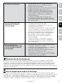
Important Safety Information
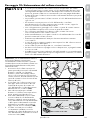
Explanation of attention words and symbols used in this product manual
This is the safety alert symbol. It is used to alert you to potential personal injury hazards. Obey all
safety messages that follow this symbol to avoid possible injury or death.
WARNING indicates a hazardous situation which, if not avoided, could result in
death or serious injury.
CAUTION, used with the safety alert symbol, indicates a hazardous situation
which, if not avoided, could result in minor or moderate injury.
CAUTION, used without the safety alert symbol, indicates a hazardous situation
which, if not avoided, could result in harm to your pet.
NOTICE is used to address practices not related to personal injury.
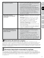
• Do not use this product if your pet is prone to aggressive behaviour. Aggressive pets can cause severe
injury or death to their owners and others. If you are not sure that this product is right for your pet, please
talk to your veterinarian or a certified trainer.
• Underground cables can carry high voltage. Have all underground cables marked before you dig to
bury your wire. In most areas this is a free service. Avoid these cables when you dig.
• Do not attempt to cut into or pry open the battery. Be sure to discard any used battery properly.
• Never incinerate, puncture, deform, short-circuit or charge with an inappropriate charger. Fire,
explosion, property damage or bodily harm may occur if this warning is not followed.
• There is a risk of explosion if a battery is replaced by an incorrect type. Do not short circuit, mix old and
new batteries, dispose of in fire or expose to water. When batteries are stored or disposed, they must be
protected from shorting.
• Follow all safety instructions for your power tools. Be sure to always wear your safety goggles.
• Do not install, connect or remove your system during a lightning storm. If the storm is close enough for
you to hear thunder, it is close enough to create hazardous surges.
• To avoid electric shock, use the fence transmitter indoors in a dry location only.

petsafe.com 3
DEITNL
ES
FR
EN
• Wire on top of the ground may be a trip hazard. Be careful when placing wires and testing the system.
• This product is not a toy. Keep it away from the reach of children.
• This PetSafe
®
Basic In-Ground Fence
™
System is NOT a solid barrier. It is designed to act as a deterrent
to remind pets to remain within the established boundary by use of static stimulation. It is important that
you reinforce training with your pet on a regular basis. Since the tolerance level to static stimulation
varies from pet to pet, Radio Systems Corporation CANNOT guarantee that the system will, in all cases,
keep a pet within the established boundary. Not all pets can be trained to avoid crossing the boundary!
Therefore, if you have reason to believe that your pet may pose a danger to others or harm himself if
he is not kept from crossing the boundary, you should NOT rely solely upon this system to confine your
pet. Radio Systems Corporation shall NOT be liable for any property damage, economic loss or any
consequential damages sustained as a result of any animal crossing the boundary.
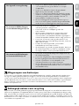
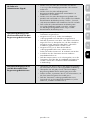
• Proper fit of the receiver collar is important. A receiver collar worn for too long or made too tight on the
pet’s neck may cause skin damage, ranging from redness to pressure ulcers; this condition is commonly
known as bed sores.
• Avoid leaving the receiver collar on the pet for more than 12 hours per day.
• When possible reposition the receiver collar on the pet’s neck every 1 to 2 hours.
• Regularly recheck the fit to prevent excessive pressure; follow the instructions in this product manual.
• Never connect a lead to the receiver collar. It will cause excessive pressure on the contact points.
• When connecting a lead to a separate collar, do not allow it to put pressure on the receiver collar.
• Wash the pet’s neck area and the contact points of the receiver collar weekly with a damp cloth.
• Examine the contact area daily for signs of a rash or a sore.
• If a rash or sore is found, discontinue use of the receiver collar until the skin has healed.
• If the condition persists beyond 48 hours, see your veterinarian.
• For additional information on bed sores and pressure necrosis, please visit our website.
• You may need to trim the hair in the area of the contact points. However, never shave the pet’s neck; this
may lead to a rash or infection.
• The boundary width of the system must be tested whenever an adjustment is made to the pet area to
prevent unintended stimulations to your pet.
• Always remove your pet’s receiver collar before performing any transmitter testing or adjustments. This
will prevent unintended static stimulations.
• If possible, do not use an outlet protected with a residual current device (RCD) or a ground fault circuit
interrupter (GFCI). The fence system will function, but in rare cases, nearby lightning strikes may cause
the RCD or GFCI to trip. Without power, your pet may be vulnerable to escape. You will have to reset the
RCD or GFCI to restore power to the system.
• Proper training of your pet is essential to successfully using the system. During the first 2 weeks of
training, do not use the system without direct supervision of your pet.
• Before you begin installing the boundary wire, unplug the fence transmitter.
• Avoid damaging the insulation of the loop wire; damage may cause areas of weak signal and lead to
failure of the boundary.
• Use care when mowing or trimming your grass not to cut the boundary wire.
• To protect the transmitter, disconnect the boundary wire and unplug the power adaptor from the outlet
when the system will not be used for long periods of time or prior to thunderstorms. This will prevent
power surges from damaging the transmitter.

petsafe.com4
ENFRES
NL
IT
DE
Table of Contents
In the Box ........................................................................................................................................................................5
You May Also Need ......................................................................................................................................................5
How the System Works .................................................................................................................................................5
Key Definitions ...............................................................................................................................................................6
Operating Guide ..................................................................................................................................................7
Step 1: Have Your Utilities Marked ...................................................................................................................... 7
Step 2: Install the Fence Transmitter ..................................................................................................................... 7
Step 3: Design Your Boundary Zone ...................................................................................................................9
Step 4: Position, Twist and Splice the Boundary Wire ..................................................................................... 12
Step 5: Connect the Boundary Wire to the Fence Transmitter ........................................................................ 13
Step 6: Prepare the Receiver Collar ...................................................................................................................14
Step 7: Set the Boundary Width and Test the Receiver Collar .......................................................................16
Step 8: Bury the Boundary Wire ........................................................................................................................18
Step 9: Place the Boundary Flags ......................................................................................................................19
Step 10: Fit the Receiver Collar ..........................................................................................................................20
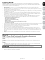
Training Guide .....................................................................................................................................................22
Phase 1: Day 1—Tone-Only Training for Boundary Awareness ....................................................................22
Phase 2: Days 2 Through 4—Boundary Awareness with Static Stimulation .................................................23
Phase 3: Days 5 Through 8—Distraction Phase ...............................................................................................24
Phase 4: Days 9 Through 14—Supervision Off the Lead ................................................................................25
Phase 5: Days 15 to 30—Pet Monitoring ..........................................................................................................25
Taking Your Pet Out of the Pet Area ........................................................................................................................... 25
System Test ....................................................................................................................................................................26
Wire Break Location Test ............................................................................................................................................27
Troubleshooting ...........................................................................................................................................................28
Battery Disposal ...........................................................................................................................................................29
Important Recycling Advice .......................................................................................................................................29
Terms of Use and Limitation of Liability ....................................................................................................................30
Compliance ..................................................................................................................................................................30
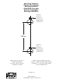
Warranty ....................................................................................................................................................................... 31
Mounting Template ................................................................................................................................................... 184

petsafe.com 5
DEITNL
ES
FR
EN
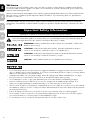
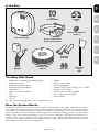
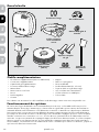
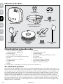
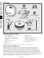
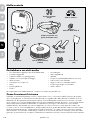
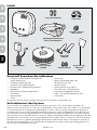
In the Box
You May Also Need
• Additional wire and flags (Part #PRFA-500)
• Additional wire nuts
• Additional gel-filled capsules
• Drill and mounting hardware
• Tape measure
• Small cross-head screwdriver
• Pliers
• Staple gun
• Scissors
• Lighter
• Shovel or lawn edger
• Wire stripping pliers
• Waterproofing compound (e.g. silicone caulk)
• PVC pipe or hose pipe
• Circular saw with masonry blade
• Non-metallic collar and lead
• Electrical tape
For setup and training help please visit www.petsafe.com.
How the System Works
The PetSafe
®
Basic In-Ground Fence
™
System has been proven safe, comfortable, and effective for pets
over 3.6 kg. The system works by producing a radio signal from the fence transmitter through up to 610 m
of boundary wire. The boundary wire is buried or attached to a fixed object to enclose the pet area. You
temporarily define this pet area with boundary flags for a visual aid in training your pet. Your pet wears a
receiver collar with contact points that touch his neck, and once trained, is allowed to roam freely in the
pet area. When your pet reaches the warning zone, the receiver collar gives a warning beep. If your pet
continues into the static stimulation zone, a safe stimulation will be delivered through the contact points to
get his attention until he returns to the pet area.
Test Light
Tool
Gel-filled
Capsules
Receiver Collar with
Short Contact Points
PetSafe
®
RFA-67D-11
Battery
Fence Transmitter
Boundary
Flags
(50)
Power
Adaptor
Boundary Wire
(150 m) Wire Nuts
Long
Contact Points

petsafe.com6
ENFRES
NL
IT
DE
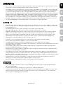
Key Definitions
Fence Transmitter: Transmits the signal through the
boundary wire.
Pet Area: The area within your garden where your pet can
roam freely.
Warning Zone: The outer edge of the pet area where your
pet’s receiver collar begins to beep, warning him not to go
into the static stimulation zone.
Static Stimulation Zone: The zone beyond the warning
zone where your pet’s receiver collar will emit a static
stimulation, signalling him to return to the pet area.
Boundary Width: The combination of the warning zone
and the static stimulation zone.
Receiver Collar: Receives the radio signal from the
boundary wire.
Stimulation Level Button: Adjusts the level of static
stimulation your pet receives in the static stimulation zone.
Receiver Indicator Light: Indicates the level of stimulation
at which the receiver collar is set. This light also indicates
battery status.
Contact Points: Deliver the safe static stimulation when your
pet moves into the static stimulation zone.
Power Jack: Where the power adaptor plugs into the
fence transmitter.
Boundary Wire Terminals: Where the boundary wires
connect to the fence transmitter in order to complete a
continuous loop.
Loop Indicator Light: Indicates that the boundary
wire makes a complete loop, enabling the signal to
be transmitted.
Boundary Width Control: Adjusts the width of the
warning and static stimulation zones. Note: Adjusting this
knob does not change the level of static stimulation on the
receiver collar.
Static
Stimulation
Zone
Warning
Zone
Pet Area
Boundary
Width
Boundary
Width
Control
Power
Light
Power
Jack
Loop
Indicator
Light
Boundary Wire
Terminals
Receiver
Indicator Light
Battery
Contact Points
Stimulation
Level Button
Receiver Collar
Fence Transmitter

petsafe.com 7
DEITNL
ES
FR
EN
Operating Guide
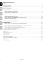
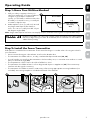
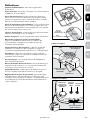
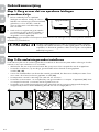
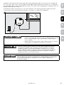
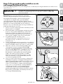
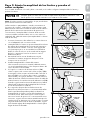
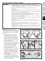
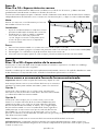
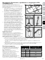
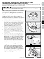
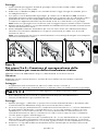
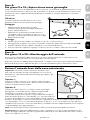
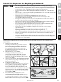
Step 1: Have Your Utilities Marked
1. Call your utility company to have your
utility lines marked. If you have neighbours
using an in-ground pet containment
system, you will want to ask them where the
boundary is located. Trust us, you really do
not want to skip this step.
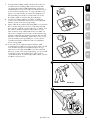
2. Make a plan for how you will work around
any large metal objects (like sheds) or
wires. You can cross utility lines but only at
90-degree angles (1A).
Note: Large metal objects and wires can amplify and/or modulate radio signals in unpredictable ways.
Underground cables can carry high voltage. Have all underground cables marked
before you dig to bury your wire. In most areas, this is a free service. Avoid these
cables when you dig.
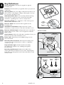
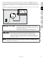
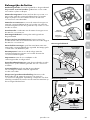
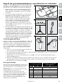
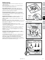
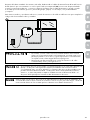
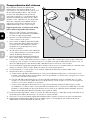
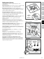
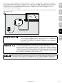
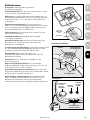
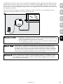
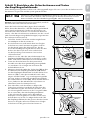
Step 2: Install the Fence Transmitter
Find a place to install the fence transmitter. There are a few things to consider when choosing an outlet for
your transmitter:
• We recommend using an outlet at least 10 m from the breaker box.
• The transmitter should be indoors, in a dry, ventilated and protected area (2A, 2B).
• You will need to run wire from the transmitter to the boundary wire, so it must be near window or a wall
that you can drill through (2A).
• The temperatures of the location should not fall below -23°C.
• The transmitter should be at least 1 m from large metal objects or appliances (2C). These items may
interfere with the signal consistency.
• The transmitter should be secured to a stationary surface using appropriate mounting hardware (not
included). A mounting template is included in the back of this manual.
90°
3 m
Buried Cable
Boundary
Wire
3 m
1A
1 m
1 m
2B 2C2A

petsafe.com8
ENFRES
NL
IT
DE
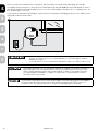
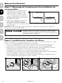
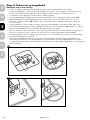
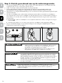
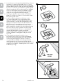
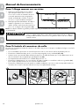
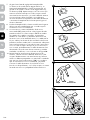
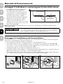
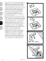
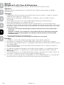
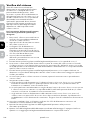
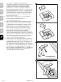
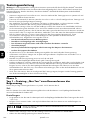
Once you have mounted the fence transmitter, the boundary wire must exit the building. This can be
accomplished via a window or through a hole drilled through the wall (2D). Ensure the drill path is clear of
any utilities. Make sure the boundary wire is not cut off or pinched by a window, door, or garage door, as
this can damage it over time.
To prevent fires and electrical hazards, install the fence transmitter in buildings that are in accordance with
state and local electrical codes.
• Do not install, connect or remove your system during a lightning storm. If the
storm is close enough for you to hear thunder, it is close enough to create
hazardous surges.
• To avoid electric shock, use the fence transmitter indoors in a dry location only.
If possible, DO NOT use an outlet protected with a residual current device (RCD) or
a ground fault circuit interrupter (GFCI). The fence system will function, but in rare
cases, nearby lightning strikes may cause the RCD or GFCI to trip. Without power,
your pet may be vulnerable to escape. You will have to reset the RCD or GFCI to
restore power to the system.
To protect the transmitter, disconnect the boundary wire and unplug the power adaptor
from the outlet when the system will not be used for long periods of time or prior to
thunderstorms. This will prevent power surges from damaging the transmitter.
2D

petsafe.com 9
DEITNL
ES
FR
EN
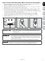
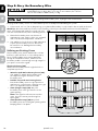
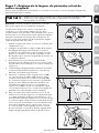
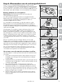
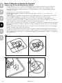
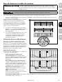
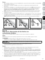
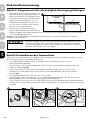
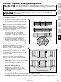
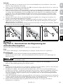
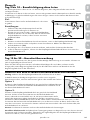
Step 3: Design Your Boundary Zone
Basic Planning Tips
• Always design your layout, position the boundary wire and test the system as outlined in this product
manual before burying the boundary wire. You do not want to find out after burying the wire that there is
a problem with your layout or a loose connection somewhere.
• Sample layouts are provided in this section.
• The boundary wire must start at the fence transmitter and make a continuous loop back (3A).
• Always use gradual turns at the corners with a minimum of 1 m radius to produce a more consistent
boundary (3B). Do not use sharp turns; this will cause gaps in your boundary.
• Create areas in your garden that allow your pet to safely cross over the boundary wire without static
stimulation by twisting the boundary wires together 30 times per m (3C). This cancels the signal and
allows your pet to safely cross over that area.
• To properly contain your pet, we recommend setting a boundary width for the warning and static
stimulation zones to approximately 4 m–6 m (2 m to 3 m on each side of the wire).
• Avoid making passageways too narrow for your pet to move about freely (e.g., along the sides of
a house).
• The receiver collar can be activated inside the house if the boundary wire runs along the outside wall
of the house. If this occurs, remove your pet’s receiver collar before bringing him inside, decrease the
range using the boundary width control knob or consider an alternate layout.
3A
3B

petsafe.com10
ENFRES
NL
IT
DE
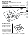
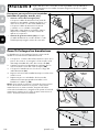
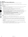
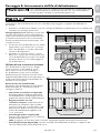
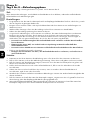
Single or Double Loop Layout
The containment area can be created by using either a single boundary wire that is placed around the entire
property (3C) or by doubling the boundary wire along the same path (3E).
Single Loop Boundary
• To create a containment area for the entire property
• For exclusion areas around flower gardens, landscaping, or pools
With a single loop layout, the boundary wire starts at the fence transmitter, advances out to the garden,
continues all the way around the perimeter of the property and connects back to the fence transmitter. This
forms a boundary zone with a single wire.
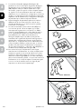
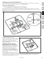
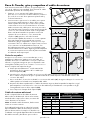
Sample 1: Perimeter Loop (3C) The
perimeter loop is the most common layout.
This will allow your pet to freely and safely
roam your entire property. It can also protect
flower gardens, pools, and landscaping.
Sample 2: Full Perimeter Loop Using
Existing Fence (3D) This layout allows you
to include your existing fence as part of your
layout and keep your pet from jumping out
or digging under your existing fence. This
layout also greatly reduces the installation
time since most of the wire will not need to
be buried.
Run the wire from the fence transmitter to
point A, then to point B and so on (B to
C to D to E) all the way around the entire
property until back to point A again.
The wires from point A will then need to be twisted and connected back to the fence transmitter inside
your home.
D
E
A
C
B
3D
3C
Wire
Splices
Place
Transmitter
Inside
Pets Can
Safely Cross
Twisted Wires
Pets Can
Safely Cross
Twisted Wires
30 Twists/m

petsafe.com 11
DEITNL
ES
FR
EN
Double Loop Boundary
• To section off only one boundary area or one
section of your garden (e.g., front property
only, or waterfront property)
• The 2 parallel sections of the double
boundary wire must be separated by a
minimum of approximately 1.5 m from
each other in order to avoid cancelling out
the signal as well as provide an adequate
boundary width (3E)
• A double loop layout requires twice as
much wire as a single loop layout because it
doubles back along the same path
With a double loop layout, the boundary wire
starts at the fence transmitter, advances out to the
garden and continues to form a boundary zone in
one section of your property (e.g., front property
only). Then the wire makes a U-turn back along
the same path and connects back to the fence
transmitter. This forms a boundary zone with a
double wire.
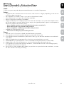
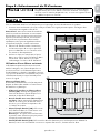
Sample 3: Front Property or Back Property
Only (3E)
From the fence transmitter, run the wire to point A,
then to point B and so on (B to C to D to E to F).
Next, make a U-turn and follow your path all the
way back to point G, keeping the wire separated
by at least 1.5 m. When you get back to the house
(G), make a sharp turn along the side of the house
back to point A. Finally, twist the wires from point
A and connect them back to the fence transmitter.
Sample 4: Front Boundary Only (3F)
From the fence transmitter, run the wire to point
A, then to point B. Make a U-turn and follow your
path back to point A, keeping the wire separated
by at least 1.5 m. Then twist the wires from point A
and connect them back to the fence transmitter.
Sample 5: Waterfront Property (3G)
From the fence transmitter, run the wire to point
A, then to point B. Make a U-turn and follow your
path to C, then to D, then to E. Next, make another
U-turn and follow the same path all the way back
to point A, keeping the wire separated by at least
1.5 m. Finally, twist the wires from point A and
connect them back to the fence transmitter.
Sample 6: Wire Loop Attached to Existing
Fence (3H)
This layout allows you to include your existing
fence as part of your layout and keep your pet
from jumping out or digging under your existing
fence. It reduces the amount of wire which will
need to be buried. From the fence transmitter run
the wire to point A, then to point B and so on (B to
C to D to E to F). Next, make a U-turn and follow
your path all the way back to point A, keeping the
wire separated by at least 1.5 m. Finally, twist the
wires from point A back to the fence transmitter.
A
C
D
E
B
1.5 m
3E
3F
3G
3H
A
C
D
E
F
B
1.5 m
A
B
1.5 m
E
F
B
Place Transmitter Inside
A
A
G
G
D
C
1.5 m

petsafe.com12
ENFRES
NL
IT
DE
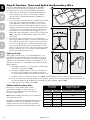
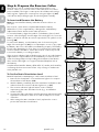
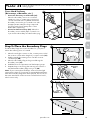
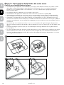
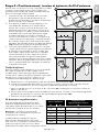
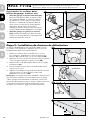
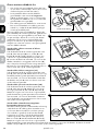
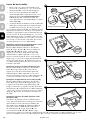
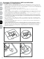
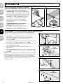
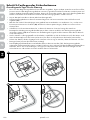
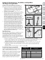
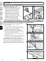
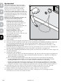
Step 4: Position, Twist and Splice the Boundary Wire
Once you have designed your layout, the next step is
to position the wire along your property. Hold off on
burying the wire until you have tested the system first.
1. Start with one end of the wire at the transmitter, but
do not plug it in yet. Run the wire outdoors all the
way around your planned perimeter and back to
the transmitter.
2. You will need to twist the 2 wires together for the area
running from the transmitter inside your home out
to the garden so that your pet can cross this section
without a stimulation. Twisting both ends of the wire
together 30 times per metre cancels the signal. Keep
in mind that crossover areas will only work when set
up within the containment area. Straight crossover
breaks along the perimeter, such as across driveways
(4A), cannot be created and the signal will not be
cancelled.
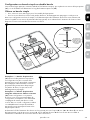
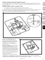
3. The fastest way to twist 2 wires is to cut 2 pieces a
little longer than the length you need, twist them, and
then “splice” in that section. Anchor one end of the 2
wires to something secure, and insert the other end
into a power drill. Pull the wire taut and then use the
drill to slowly twist the wire. Follow the splicing guide
below to learn how to reconnect this twisted portion
back to the main boundary wire.
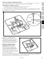
Splicing Guide
Although not required, it is recommended that you cut
and splice the wire between each twisted section. Your
Basic In-Ground Fence
™
System comes with 2 gel-filled
capsules to ensure that your splices are waterproof. You
can give us a call if you would like to purchase more gel-
filled capsules.
a. Strip approximately 1 cm of insulation off the ends
of the wires to be spliced (4B).
b. Insert the stripped ends into the wire nut and twist
the wire nut around the wires. Make sure there is
no copper exposed beyond the end of the wire nut.
c. Tie a knot 7.5 cm–10 cm from the wire nut (4C). Ensure that the wire nut is secure on the wire splice.
d. Once you have securely spliced the wires together, open the lid of the gel-filled capsule and insert the
wire nut as deeply as possible into the waterproof gel inside the capsule (4D).
e. Snap the lid of the capsule shut (4E).
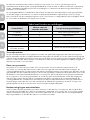
Additional Boundary Wire
Extra spools of boundary wire can be
purchased in lengths of 150 m per spool
where you purchased the kit or through the
Customer Care Centre.
Note: When adding boundary wire, it must act
as a continuous loop.
The table on the right indicates the approximate
length of boundary wire needed for a square,
single loop layout. The length will vary due to
the amount of twisted wire and the layout used.
1cm
}
1cm
}
4B
4C
4D
4E
4A
Area to be
enclosed
Approximate wire
length required
Ar Ac M
10
1
⁄4
127
13
1
⁄3
146
20
1
⁄2
180
40 1 255
80 2 360
200 5 570

petsafe.com 13
DEITNL
ES
FR
EN
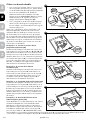
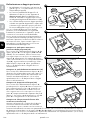
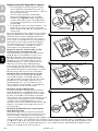
Step 5: Connect the Boundary Wire to the Fence Transmitter
1. Run the boundary wire through a window, under a door, through a crawl space vent, or any other
appropriate available access. You can also drill a hole through your wall.
2. Strip 1 cm of insulation from the ends of the boundary wire.
3. Press the red tabs on the fence transmitter and insert the twisted wire into the boundary wire terminals
(5A). Make sure wires do not touch each other at the terminals.
4. Turn the boundary width control knob to 10. This will set the boundary width at the maximum width.
5. Connect the power adaptor to the transmitter at the power jack and plug the power adaptor into a
working outlet. The power adaptor comes with the North American plug installed and additional plugs
for the UK, Europe, and Australia. To change the plug:
a. Push in the tab on the power adaptor and remove the plug by sliding it off as shown (5B).
b. Slide the proper plug for your electrical outlet onto the power adaptor as shown (5C).
6. The power light and loop indicator light should come on. If this does not happen, check out our
troubleshooting section.
• Do not install, connect, or remove your system during a lightning storm. If the
storm is close enough for you to hear thunder, it is close enough to create
hazardous surges.
• To avoid electric shock, use the fence transmitter indoors in a dry location only.
• If possible, do not use an outlet protected with a residual current device (RCD) or
a ground fault circuit interrupter (GFCI). The fence system will function, but in rare
cases, nearby lightning strikes may cause the RCD or GFCI to trip. Without power,
your pet may be vulnerable to escape. You will have to reset the RCD or GFCI to
restore power to the system.
• Before you begin installing the boundary wire, unplug the fence transmitter.
To protect the transmitter, disconnect the boundary wire and unplug the power adaptor
from the outlet when the system will not be used for long periods of time or prior to
thunderstorms. This will prevent power surges from damaging the transmitter.
5A
5B 5C

petsafe.com14
ENFRES
NL
IT
DE
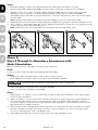
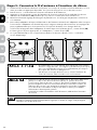
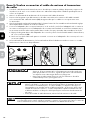
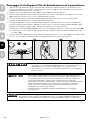
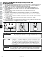
Step 6: Prepare the Receiver Collar
There are two sets of contact points that can be used on your
receiver collar. Your receiver collar comes with the short contact
points installed. The longer contact points should be used on dogs
with long hair. Tighten the contact points using test light tool (6A)
one-half turn beyond finger tight. Check the tightness weekly.
To Insert and Remove the Battery
Note: Do not install the battery while the receiver collar is on
your pet.
This receiver collar utilises a replaceable PetSafe
®
battery
(R FA - 67 D -11). This unique battery is designed to make battery
replacement easier and increase water protection.
To insert the battery, align the symbols on the battery (arrow) and
receiver collar (triangle). Use the edge of the test light tool to turn the
battery clockwise until the arrow lines up with the lock symbol on the
housing (6B).
To remove the battery, turn the battery anti-clockwise using the
edge of the test light tool (6C). Do not attempt to cut into or pry open
the battery. Be sure to discard the used battery properly. The battery
life will vary depending on how often your pet tests the system and
receives a static stimulation. Check the receiver collar every month
to ensure the battery is working properly.
If the receiver indicator light is flashing every 4 to 5 seconds, battery
replacement is required. Remove the old battery from the receiver
collar. Discharge all power by holding the stimulation level button
down until the LED light is no longer illuminated. Replace with a
new battery.
A replacement PetSafe
®
battery (RFA - 67 D -11) can be purchased by
contacting the Customer Care Centre or by visiting our website at
www.petsafe.com.
To Set the Static Stimulation Level
Read all steps before attempting to set the static stimulation level.
1. Remove the clear plastic cover with the test light tool to expose
the stimulation level button (6D).
2. With the battery installed, press the stimulation level button and
release when the receiver indicator light turns on (6E).
3. The receiver indicator light will emit a series of flashes
representing the static stimulation level (e.g., 4 red flashes
means level 4).
4. Increase the static stimulation level by pressing and releasing the
stimulation level button within 5 seconds of the previous series
of flashes.
5. After setting the static stimulation level, replace the cover to
protect the stimulation level button.
6A
6B
6C
6D
6E

petsafe.com 15
DEITNL
ES
FR
EN
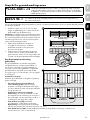
The static stimulation levels increase in strength from 1 to 5. Pressing the stimulation level button while
the receiver collar is on level 5 will cause the receiver collar to revert to level 1. Refer to the function and
response table to choose the static stimulation level that best fits your pet.
The receiver collar is equipped to automatically increase the level of static stimulation the longer your pet
remains in the static stimulation zone if the collar is set at level 2 or above.
The receiver indicator light acts as a low battery indicator, flashing every 4 to 5 seconds when replacement
is required.
Function and Response Table
Indicator Light Static Stimulation Level Receiver Collar Function
1 red flash 1 None—tone only
2 red flashes 2 Low stimulation
3 red flashes 3 Medium stimulation
4 red flashes 4 Medium-high stimulation
5 red flashes 5 High stimulation
Flashes once every
4 to 5 seconds
– Indicates low battery
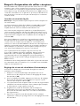
Anti-Linger Prevention
The anti-linger prevention feature keeps your pet from staying in the warning zone for long periods of
time and draining the receiver collar battery. Your pet will hear a warning tone when he reaches the
warning zone. If your pet does not return to the pet area after 2 seconds, he will receive a continuous static
stimulation until he returns to the pet area.
Run-Through Prevention
This system includes a unique run-through prevention feature so that your pet cannot “run through” the pet
area without receiving an increased level of static stimulation. The receiver collar automatically increases
the static stimulation when your pet continues more than 20% of the way through the pet fencing boundary
width. For example, if the signal is detected 3 m from the wire and your pet enters the static stimulation zone,
this feature is activated when he is approximately 2.5 m from the boundary wire. Your pet will then receive
a static stimulation that is at an increased level corresponding to the static stimulation level setting on the
receiver collar. The receiver collar is equipped to automatically increase the level of static stimulation the
longer your pet remains in the static stimulation zone if the collar is set at level 2 or above. The run-through
prevention sound is an intermittent tone.
Over-Stimulation Protection
In the unlikely event that your pet “freezes” in the static stimulation zone, this feature limits the static
stimulation duration to a maximum of 15 seconds. After 15 seconds, the static stimulation will stop and the
green indicator light will stay on for 10 seconds. The receiver collar remains locked out until your pet leaves
the static stimulation zone.

petsafe.com16
ENFRES
NL
IT
DE
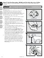
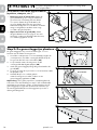
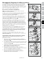
Step 7: Set the Boundary Width and Test the Receiver Collar
With the boundary wire in place and properly connected, it is time to set the boundary width and test
the system.
Always remove your pet’s receiver collar before performing any transmitter testing
or adjustments. This will prevent unintended static stimulations.
Note: The receiver collar is waterproof, which can make the
tone hard to hear.
The flashing test light, when held to the contact points,
indicates that the receiver collar is delivering static
stimulation. To best utilize the automatic run-through
prevention feature, the containment boundary width should
extend at least 2 m to 3 m on each side of the boundary
wire (total boundary width of 4 m to 6 m).
1. Apply power to the fence transmitter with the supplied
power adaptor.
2. The boundary width is adjusted by using the
transmitter’s boundary width control knob. Turn the
knob anti-clockwise until the loop indicator light is no
longer lit. Turn the knob clockwise and increase by 2
numbers. The light should turn on.
3. To identify the warning and static stimulation zones
make sure the static stimulation on the receiver collar is
set at level 5.
4. Test the boundary width of the system by selecting a
section of straight boundary wire that is at least 15 m long.
Start inside the centre of the pet area.
5. Place the test light tool contacts (7A) against the
receiver collar contact points (7B). Hold the receiver
collar at your pet’s neck height (7C) with the contact
points pointing up and the PetSafe
®
logo facing the
boundary wire. Slowly walk toward the boundary wire
until you hear the warning tone (7D). When you hear
the warning tone, you have identified the boundary
width distance (static stimulation zone).
6. Two seconds after the warning tone, the test light
will begin to flash. This flashing light can aid you in
identifying the boundary width if you have difficulty
hearing the tone. To prevent the receiver collar from
going into over-stimulation protection mode, walk
back into the pet area until the toning stops.
If the
receiver collar does not tone at the desired range,
adjust the boundary width control knob to obtain the
desired range.
Test Light Contacts
7A
7B
7C
Boundary
Wire
7D

petsafe.com 17
DEITNL
ES
FR
EN
7. Turning the boundary width control knob clockwise
increases the boundary width, while turning it anti-
clockwise decreases
it (7E). Repeat this activity as
needed until the receiver collar tones between 2 m to
3 m from the boundary wire. If using a double loop
layout, you may need to increase the separation of
the boundary wire and/or increase the size of the
boundary width to achieve the desired range.
8. Test the boundary width in a number of different
locations around the pet area until you are satisfied
that the system is functioning properly.
9. Next, walk all around the pet area (7F) to ensure there
are no areas where the receiver collar may activate
from signals coupled onto buried wires or cables. Test
the collar in and around the inside of the house as
well. As mentioned, cable and wires from cable TV,
electrical or telephone lines may conduct pet fencing
signals inside and outside the house that can activate
the pet’s collar accidentally. While rare, if this occurs,
your boundary wire is probably too close to these
outside lines and should be moved or modified as
shown in figure1A.
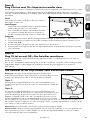
10. To test the run-through prevention feature, walk
towards the boundary wire. The receiver collar should
tone and the test light should flash brighter as you
enter the run through area (7G). If you are satisfied
that your system is functioning properly, you are ready
to start burying the boundary wire. If the receiver
collar did not tone or the test light did not flash, see the
troubleshooting section.
Boundary Wire
Pet Area
7F
7G
5
2 8
4
10
3
9
1
7
0
6
5
2 8
4
10
3
9
1
7
0
6
7E

petsafe.com18
ENFRES
NL
IT
DE
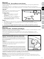
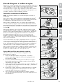
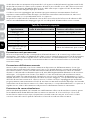
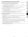
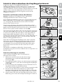
Step 8: Bury the Boundary Wire
Underground cables can carry high voltage. Have all underground cables
marked before you dig to bury your wire. In most areas, this is a free
service. Avoid these cables when you dig.
Before you begin installing the boundary wire, unplug the fence transmitter.
Burying the boundary wire is recommended to protect it and prevent disabling the system.
1. Cut a trench 2.5 cm–7.6 cm deep along your planned boundary. It only needs to be as wide as the wire.
Quick Tip: We have tried lots of tools. Lawn trenchers, which you can often rent from a local hardware
store, work great and make for a quick job. You
can also use a flat shovel, like a trenching shovel.
2. Place the boundary wire into the trench
maintaining some slack to allow it to expand
and contract with temperature variations.
3. Use a blunt tool such as a wooden paint stick
to push the boundary wire into the trench.
Be careful not to damage the boundary
wire insulation.
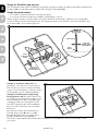
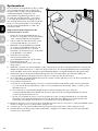
Utilizing an Existing Fence
The boundary wire can be attached to a chain
link fence, split rail fence or a wooden privacy
fence. The boundary wire can be attached
as high as needed. However, make sure the
boundary width is set at a high enough range for
your pet to receive the signal.
Chain Link Fence (8A):
Weave the boundary wire through the links or
use plastic quick ties.
• Wooden Split Rail orPrivacy Fence (8A):
Use staples to attach the boundary wire.
Avoid puncturing the insulation of the
boundary wire.
• Double Loop with an Existing Fence:
Run the boundary wire on top of the fence
and return it on the bottom of the fence to get
the 1.5 m separation that is needed.
• Gate (Single Loop) (8B): Bury the
boundary wire in the ground across the
gate opening.
Note: The signal is still active across the
gate. Your pet cannot pass through an
open gate.
• Gate (Double Loop) (8B): Bury both
boundary wires across the gate opening while
keeping them 1.5 m apart.
Single Loop
Double Loop
1.5 m 1.5 m
8B
8A
Weave Wire Into Fence
Staple Wire Into Fence

petsafe.com 19
DEITNL
ES
FR
EN
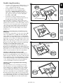
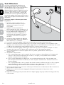
Follow all safety instructions for your power tools. Be sure to always wear your
safety goggles.
Cross Hard Surfaces
(driveways, sidewalks, etc.)
• Concrete Driveway or Sidewalk (8C):
Place the boundary wire in a convenient
expansion joint or create a groove using a
circular saw and masonry blade. Place the
boundary wire in the groove and cover with
an appropriate waterproofing compound.
For best results, brush away dirt or other
debris before patching.
• Gravel or Dirt Driveway (8D): Place the
boundary wire in a PVC pipe or water hose
to protect the boundary wire before burying.
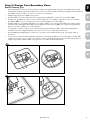
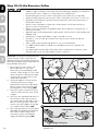
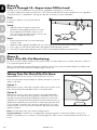
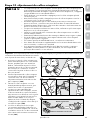
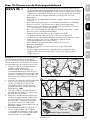
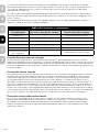
Step 9: Place the Boundary Flags
The boundary flags are visual reminders for your pet of
where the warning zone is located.
1. Place the test light contacts on the contact points. Hold
the receiver collar at the height of your pet’s neck (9A).
2. Walk towards the warning zone until the receiver
collar beeps (9B).
3. Place the boundary flag in the ground along the
boundary wire
(9C).
4. Walk back into the pet area until the beeping stops.
5. Repeat this process along the warning zone until it is
marked with boundary flags every 3 m
(9D)
.
Note: If you cannot hear the beep, refer to the test light
instructions in Step 7. To prevent an unintended stimulation,
after the boundary flags have been placed, be sure to set
the static stimulation on the receiver collar back to level 1,
which is tone only.
8C
8D
3 m
Boundary
Wire
Boundary
Wire
9A
9B
9C
9D

petsafe.com20
ENFRES
NL
IT
DE
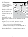
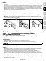
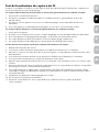
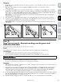
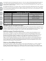
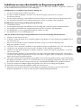
Step 10: Fit the Receiver Collar
• Proper fit of the receiver collar is important. A receiver collar worn for too long or
made too tight on the pet’s neck may cause skin damage, ranging from redness to
pressure ulcers; this condition is commonly known as bed sores.
• Avoid leaving the receiver collar on the pet for more than 12 hours per day.
• When possible reposition the receiver collar on the pet’s neck every 1 to 2 hours.
• Regularly recheck the fit to prevent excessive pressure; follow the instructions in
this product manual.
• Never connect a lead to a collar with contact points. It will cause excessive
pressure on the contact points.
• When connecting a lead to a separate collar, do not allow it to put pressure on
the receiver collar.
• Wash the pet’s neck area and the contact points of the receiver collar weekly with
a damp cloth.
• Examine the contact area daily for signs of a rash or a sore.
• If a rash or sore is found, discontinue use of the receiver collar until the skin
has healed.
• If the condition persists beyond 48 hours, see your veterinarian.
• For additional information on bed sores and pressure necrosis, please visit
our website.
• You may need to trim the hair in the area of the contact points. However, never
shave the pet’s neck; this may lead to a rash or infection.
Important: The proper fit and placement
of your receiver collar is important for
effective training. The contact points must
have direct contact with your pet’s skin on
the underside of his neck.
1. Be sure the receiver collar is off
before placing it on your pet.
Then with your pet standing, fit the
receiver collar snugly onto your pet’s
neck so that the contact points make
contact with your pet’s skin on the
underside of his neck.
2. Check the tightness of the receiver
collar by inserting one finger
between the end of a contact point
and your pet’s neck. The fit should
be snug but not constricting (10A).
3. Allow your pet to wear the receiver
collar for a few minutes, then check
it again.
4. Once you are satisfied with the fit of
the receiver collar, remove it from
your pet and trim it, but make sure to
allow room for growth or a thicker
winter coat. Use a lighter to seal the
cut so that it will not fray (10B).
5. The collar will slip if it is not properly
threaded. The slide buckle prevents
the collar from becoming loose
around your pet’s neck and the
ridges must be facing up (10C).
Slide Buckle
Ridges facing up
10C
10B
10A
La pagina si sta caricando...
La pagina si sta caricando...
La pagina si sta caricando...
La pagina si sta caricando...
La pagina si sta caricando...
La pagina si sta caricando...
La pagina si sta caricando...
La pagina si sta caricando...
La pagina si sta caricando...
La pagina si sta caricando...
La pagina si sta caricando...
La pagina si sta caricando...
La pagina si sta caricando...
La pagina si sta caricando...
La pagina si sta caricando...
La pagina si sta caricando...
La pagina si sta caricando...
La pagina si sta caricando...
La pagina si sta caricando...
La pagina si sta caricando...
La pagina si sta caricando...
La pagina si sta caricando...
La pagina si sta caricando...
La pagina si sta caricando...
La pagina si sta caricando...
La pagina si sta caricando...
La pagina si sta caricando...
La pagina si sta caricando...
La pagina si sta caricando...
La pagina si sta caricando...
La pagina si sta caricando...
La pagina si sta caricando...
La pagina si sta caricando...
La pagina si sta caricando...
La pagina si sta caricando...
La pagina si sta caricando...
La pagina si sta caricando...
La pagina si sta caricando...
La pagina si sta caricando...
La pagina si sta caricando...
La pagina si sta caricando...
La pagina si sta caricando...
La pagina si sta caricando...
La pagina si sta caricando...
La pagina si sta caricando...
La pagina si sta caricando...
La pagina si sta caricando...
La pagina si sta caricando...
La pagina si sta caricando...
La pagina si sta caricando...
La pagina si sta caricando...
La pagina si sta caricando...
La pagina si sta caricando...
La pagina si sta caricando...
La pagina si sta caricando...
La pagina si sta caricando...
La pagina si sta caricando...
La pagina si sta caricando...
La pagina si sta caricando...
La pagina si sta caricando...
La pagina si sta caricando...
La pagina si sta caricando...
La pagina si sta caricando...
La pagina si sta caricando...
La pagina si sta caricando...
La pagina si sta caricando...
La pagina si sta caricando...
La pagina si sta caricando...
La pagina si sta caricando...
La pagina si sta caricando...
La pagina si sta caricando...
La pagina si sta caricando...
La pagina si sta caricando...
La pagina si sta caricando...
La pagina si sta caricando...
La pagina si sta caricando...
La pagina si sta caricando...
La pagina si sta caricando...
La pagina si sta caricando...
La pagina si sta caricando...
La pagina si sta caricando...
La pagina si sta caricando...
La pagina si sta caricando...
La pagina si sta caricando...
La pagina si sta caricando...
La pagina si sta caricando...
La pagina si sta caricando...
La pagina si sta caricando...
La pagina si sta caricando...
La pagina si sta caricando...
La pagina si sta caricando...
La pagina si sta caricando...
La pagina si sta caricando...
La pagina si sta caricando...
La pagina si sta caricando...
La pagina si sta caricando...
La pagina si sta caricando...
La pagina si sta caricando...
La pagina si sta caricando...
La pagina si sta caricando...
La pagina si sta caricando...
La pagina si sta caricando...
La pagina si sta caricando...
La pagina si sta caricando...
La pagina si sta caricando...
La pagina si sta caricando...
La pagina si sta caricando...
La pagina si sta caricando...
La pagina si sta caricando...
La pagina si sta caricando...
La pagina si sta caricando...
La pagina si sta caricando...
La pagina si sta caricando...
La pagina si sta caricando...
La pagina si sta caricando...
La pagina si sta caricando...
La pagina si sta caricando...
La pagina si sta caricando...
La pagina si sta caricando...
La pagina si sta caricando...
La pagina si sta caricando...
La pagina si sta caricando...
La pagina si sta caricando...
La pagina si sta caricando...
La pagina si sta caricando...
La pagina si sta caricando...
La pagina si sta caricando...
La pagina si sta caricando...
La pagina si sta caricando...
La pagina si sta caricando...
La pagina si sta caricando...
La pagina si sta caricando...
La pagina si sta caricando...
La pagina si sta caricando...
La pagina si sta caricando...
La pagina si sta caricando...
La pagina si sta caricando...
La pagina si sta caricando...
La pagina si sta caricando...
La pagina si sta caricando...
La pagina si sta caricando...
La pagina si sta caricando...
La pagina si sta caricando...
La pagina si sta caricando...
La pagina si sta caricando...
La pagina si sta caricando...
La pagina si sta caricando...
La pagina si sta caricando...
La pagina si sta caricando...
La pagina si sta caricando...
La pagina si sta caricando...
La pagina si sta caricando...
-
 1
1
-
 2
2
-
 3
3
-
 4
4
-
 5
5
-
 6
6
-
 7
7
-
 8
8
-
 9
9
-
 10
10
-
 11
11
-
 12
12
-
 13
13
-
 14
14
-
 15
15
-
 16
16
-
 17
17
-
 18
18
-
 19
19
-
 20
20
-
 21
21
-
 22
22
-
 23
23
-
 24
24
-
 25
25
-
 26
26
-
 27
27
-
 28
28
-
 29
29
-
 30
30
-
 31
31
-
 32
32
-
 33
33
-
 34
34
-
 35
35
-
 36
36
-
 37
37
-
 38
38
-
 39
39
-
 40
40
-
 41
41
-
 42
42
-
 43
43
-
 44
44
-
 45
45
-
 46
46
-
 47
47
-
 48
48
-
 49
49
-
 50
50
-
 51
51
-
 52
52
-
 53
53
-
 54
54
-
 55
55
-
 56
56
-
 57
57
-
 58
58
-
 59
59
-
 60
60
-
 61
61
-
 62
62
-
 63
63
-
 64
64
-
 65
65
-
 66
66
-
 67
67
-
 68
68
-
 69
69
-
 70
70
-
 71
71
-
 72
72
-
 73
73
-
 74
74
-
 75
75
-
 76
76
-
 77
77
-
 78
78
-
 79
79
-
 80
80
-
 81
81
-
 82
82
-
 83
83
-
 84
84
-
 85
85
-
 86
86
-
 87
87
-
 88
88
-
 89
89
-
 90
90
-
 91
91
-
 92
92
-
 93
93
-
 94
94
-
 95
95
-
 96
96
-
 97
97
-
 98
98
-
 99
99
-
 100
100
-
 101
101
-
 102
102
-
 103
103
-
 104
104
-
 105
105
-
 106
106
-
 107
107
-
 108
108
-
 109
109
-
 110
110
-
 111
111
-
 112
112
-
 113
113
-
 114
114
-
 115
115
-
 116
116
-
 117
117
-
 118
118
-
 119
119
-
 120
120
-
 121
121
-
 122
122
-
 123
123
-
 124
124
-
 125
125
-
 126
126
-
 127
127
-
 128
128
-
 129
129
-
 130
130
-
 131
131
-
 132
132
-
 133
133
-
 134
134
-
 135
135
-
 136
136
-
 137
137
-
 138
138
-
 139
139
-
 140
140
-
 141
141
-
 142
142
-
 143
143
-
 144
144
-
 145
145
-
 146
146
-
 147
147
-
 148
148
-
 149
149
-
 150
150
-
 151
151
-
 152
152
-
 153
153
-
 154
154
-
 155
155
-
 156
156
-
 157
157
-
 158
158
-
 159
159
-
 160
160
-
 161
161
-
 162
162
-
 163
163
-
 164
164
-
 165
165
-
 166
166
-
 167
167
-
 168
168
-
 169
169
-
 170
170
-
 171
171
-
 172
172


Petsafe PIG19-16412 Manuale utente
- Categoria
- Cura degli animali
- Tipo
- Manuale utente
in altre lingue
- français: Petsafe PIG19-16412 Manuel utilisateur
- español: Petsafe PIG19-16412 Manual de usuario
- Deutsch: Petsafe PIG19-16412 Benutzerhandbuch
- Nederlands: Petsafe PIG19-16412 Handleiding
Documenti correlati
-
Petsafe PIG20-11041 Manuale del proprietario
-
-
-
Petsafe 3003698 Guida utente
-
Petsafe PPA11-10709 Manuale utente
-
-
-
-
-
Altri documenti
-
Num'axes CANIFUGUE Mix Manuale utente
-
SURE petcare iCWS Series Guida utente
-
-
Worx WG546E.9 Manuale utente
-
Kerbl 291130 Electric Slug Fence Starter Kit Manuale utente
-
-
Greenworks OPTIMOW Manuale del proprietario
-
Kerbl 1790 Guida utente
-
Gallagher G50405 Manuale utente
-
 Staywell 400 Series Magnetic Manuale utente
