
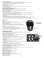
RM20
7)'.BSJOF3BEJP
( EN )
( DE )
( FR )
( IT )
( ES )

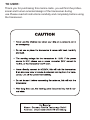
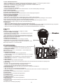
Thank you for purchasing this marine radio. you will find rhe profes-
sional and human oriented design of the transceiver during
use.Please read all instructions carefully and completely before using
the transceiver.
TO USER:

CONTENTS
PREPARATION
Supplied accessories
Transceiver mounting
Antenna connection
Connections
Dimensions
PANEL DESCRIPTIO
Front panel
Microphone
Function display
BASIC OPERATION
Power ON / OFF
Receiving and transmitting
Channel group selection
Channel selection
Call channel programming
Channel comments
Microphone lock function
Display backlighting
Vibration water draining function
SCAN OPERATIO
Scan types
Setting TAG channels
Starting a scan
DUAL-WATCH/TRI-WATCH
Description
Operation
DSC OPERATION
MMSI code programming
MMSI code check
DCS address ID
Distress call
Individual call
Group call
All Ships call
Geographical Area call
GPS Position indication
SET MODE
Set mode programming
Set mode items
CHANNEL LIST
SPECIFICATIONS
TROUBLESHOOTING
WARNING
EN(1-26)
DE(27-33)
ES(34-50)
FR(51-67)
IT(68-84)
.................................................................................................................................... 01
............................................................................................................................ 01
........................................................................................................................... 01
.............................................................................................................................. 01
........................................................................................................................................... 02
............................................................................................................................................ 02
......................................................................................................................... 02
............................................................................................................................................. 02
............................................................................................................................................ 03
.................................................................................................................................... 03
........................................................................................................................... 04
...................................................................................................................................... 04
................................................................................................................... 04
...................................................................................................................... 04
.................................................................................................................................. 04
................................................................................................................... 04
.............................................................................................................................. 05
.................................................................................................................... 05
............................................................................................................................. 05
....................................................................................................... 05
.............................................................................................................................. 05
............................................................................................................................................ 05
.......................................................................................................................... 05
....................................................................................................................................... 06
............................................................................................................ 06
........................................................................................................................................... 06
............................................................................................................................................... 06
.............................................................................................................................. 06
..................................................................................................................... 06
.................................................................................................................................. 06
..................................................................................................................................... 07
.......................................................................................................................................... 07
....................................................................................................................................... 08
............................................................................................................................................... 08
....................................................................................................................................... 09
......................................................................................................................... 09
....................................................................................................................... 09
............................................................................................................................................ 10
........................................................................................................................ 10
...................................................................................................................................... 11
...................................................................................................................................... 11
.................................................................................................................................. 12
......................................................................................................................... 13
.............................................................................................................................................. 14

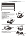
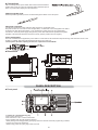
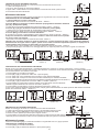
PREPARATION
Ŷ6XSSOLHGDFFHVVRULHV
The following accessories are supplied:
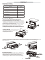
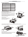
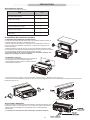
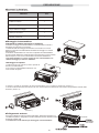
Ŷ7UDQVFHLYHUPRXQWLQJ
Ƈ8VLQJWKHVXSSOLHGPRXQWLQJEUDFNHW
The universal mounting bracket supplied with your transceiver allows
overhead or dashboard mounting.
1.Fix the mounting bracket to shelf or dashboard with the supplied screws
and mount the transceiver to the mounting bracket with the knob bolts.
2.Mount the transceiver so that the face of the transceiver is at 90"to your
line of sight when operating it and tighten the knob bolts so that the
transceiver Is securely mounted.
• You may use a spongy cushion between the transceiver and
mounting bracket to reduce the vibration.
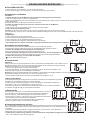
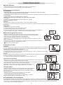
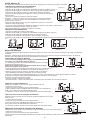
Ƈ(PEHGGHGPRXQWLQJ
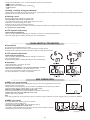
1. Cut a hole into the instrument panel (or wherever you plan to mount the
transceiver).
2. Slide the transceiver through the holes
as shown below.
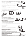
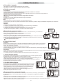
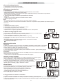
3. Attach the clamps on either side of the transceiver with 2 supplied bolts.(Image1)
4. Tighten the end bolts on the clamps so that the clamps press firmly against the Inside of the Instrument control panel.(Image2)
Ŷ$QWHQQDFRQQHFWLRQ
Please connect an antenna before transmitting. Select the antenna with the relative
frequency and connect on the ANT antenna connector. Use the antenna and low
loss concentric with the same natural impedance 50Q
• Transmitting without an antenna may damage the transceiver.
ITEM QTY
DC power cable
Spare fuse
Mounting bracket
Screws for mounting bracket
Microphone hanger
Instruction manual
1
1
1
1
1
1
(Image1) (Image2)
01

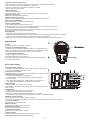
PANEL DESCRIPTION
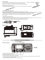
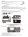
Ŷ&RQQHFWLRQV
After connecting the DC power cable, GPS receiver lead and external
speaker lead, cover the connector and leads with an adhesive tape as
below, to prevent water seeping into the transceiver.
Ƈ([WHUQDOVSHDNHUOHDG
External speakers (speakers) can be connected through the cables on the rear panel.
Ƈ'&SRZHUFRQQHFWRU
Connect the supplied DC power cable from this connector to an external 13.8V
DC power source. Do not connect to 24V storage battery. If insufficient current is supplied to the radio, t
he display may dim during transmission, or the transmission output power may drop significantly.
Connect to a 13.8V DC power supply through a DC power cable. Note that the positive and negative
polarities of the terminals should beconnected correctly. (Red is positive, black is negative)
Ƈ)XVHUHSODFHPHQW
One fuse is installed in the supplied DC power cable. If a fuse blows or the transceiver stops functioning, track down the source of the
problem, If possible, and replace the damaged fuse with a new, rated one,
• Please power off before replacing the fuse, the required fuse is DC15A/32V.
Ŷ'LPHQVLRQV
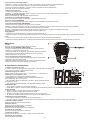
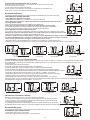
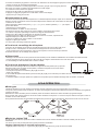
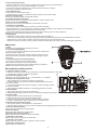
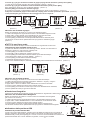
Ŷ)URQWSDQHO
1. Channel 16 / Call Channel Key [16]
-Push to select Channel 16.
-Push and hold for 1 sec. to select call channel.
"CALL" appears when the call channel is selected.
- While pushing and holding [CH/WX], push [16] to enter the channel comments programming condition.
- Push to move the cursor backward.
- While turning power ON, push [16] to enter set mode.
02

2. Channel / Weather Channel Key
-Select and toggle the regular channel and weather channel when pushed momentarily.
-Push and hold for 1 sec. to start Dualwatch or Trl-watch.
-Push to stop Dualwatch or Tri-watch when either is activated.
-Push to move the cursor forward.
3.DSC/Position Key
->Push to enter DSC menu.
->Push and hold for 1 sec. to show the current position from a GPS receiver.
4.Squelch Control [SQL]
Rotate to set the squelch threshold level.
5.Power/Volume Control [VOL]
Rotate to turn the transceiver power ON and OFF and adjusts the audio level.
6.Distress Key [DISTRESS]
Push and hold for 5 sec. to transmit a Distress call.
7.Scan / Tag Key [SCAN]
-Push to start or stop the normal or priority scan.
-Push and hold for 1 sec. to set or clear the displayed channel as a TAG (scanned) channel.
The favorite channels are set by the TAG channel setting.
-Push and hold [HI/LO] and [SCAN] to clear all TAG channels in the selected channel group.
Repeat above procedure to set all TAG channels.
>Ÿ@>ź@>8O&@
-> Select the operating channels, set mode settings, etc.
-> Select one of three channel groups in sequence when both keys are pushed.
-> While turning power ON,push and hold both keys to activate the Vibration water draining function.
Ŷ0LFURSKRQH
1. [PTT]
Push and hold to transmit; release to receive.
&KDQQHO83'2:1.H\V>Ÿ@>ź@
-> Push either key to change the operating channel, set mode settings, etc.
->When the favorite channel function is turned ON, push either key to select
the favorite channels in the selected channel group in sequence.
3. Transmit Power Key [HI/LO]
-> Push to toggle the power high and low.
Some channels are set to low power only.
->While push and hold [HI/LO], turn power ON to toggle the microphone
lock function ON and OFF.
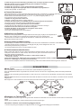
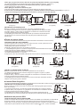
Ŷ)XQFWLRQGLVSOD\
1.Channel Number Readout
-> Indicate the selected operating channel number. (Refer to channel list)
-> In set mode, indicate the selected condition.
2.Channel Group Indicator
Indicate whether a U.S.A. “U”, International “I” or Canadian “C” channel is in use.
3.Channel Comment Indicator
-> Channel comment appears if programmed.
-> “LOW BATTERY" scrolls when the battery voltage drops approx.
10.8V DC or below.
-> "SC” blinks during priority scan; “SCAN" blinks during normal scan.
-> “DW” blinks during Dualwatch; “TW blinks during Tri-watch.
4.DSC Indicators
-> "DSC” appears when a DSC call is received.
-> "POS REPLY” appears when a position reply call or position report reply
call is received.
5.GPS Indicator
-> Appears when GPS receiver is working properly.
-> Appears when valid position data is received.
-> Disappears when GPS receiver does network or it is abnormal.
-> The number of signals behind the GPS indicates the number of satellites received.
6.Weather Channel Indicator
-> “WX” appears when a weather channel is selected.
-> “WX ALT" appears when the weather alert function is in use; blinks when an alert tone is received.
7.Low Power Indicator
Appears when low power is selected.
'XSOH[,QGLFDWRU
Appears when a duplex channel is selected.
9.Call Channel Indicator
Appears when the call channel is selected.
10.TAG Channel Indicator
Appears when a TAG channel is selected.
11.Busy Indicator
Appears when receiving a signal or when the squelch opens.
12.Transmit Indicator:Appears while transmitting.
03

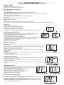
BASIC OPERATION
Ŷ3RZHU212))
1.Rotate [VOL] clockwise to turn power on;
2.Rotate [VOL] counter-clockwise to turn power off.
Ŷ5HFHLYLQJDQGWUDQVPLWWLQJ
Ƈ7UDQVPLWWLQJ
1.Push [HI/LO] on the microphone to select the output power if necessary.
•"LOW” appears when low power is selected.
•Choose low power for short range communication, choose high power for longer distance communication.
•Some channels are for low power only.
2.Push and hold [PTT] to transmit, then speak Into the microphone.
•“TX“ appears.
•Channel 70 cannot be used for transmission other than DSC.
3.Release [PTT] to receive.
Note:
•Do not transmit before connecting the antenna, this will ruin the transceiver.
•The TOT (Time-out Timer) function inhibits continuous transmission over a preset time period after the transmission starts.
Ƈ5HFHLYLQJ
1.Set the audio and squelch levels.
2.Rotate [SQL] fully counterclockwise In advance.
3.Rotate [VOL] to adjust the audio output level.
4.Rotate [SQL] clockwise until the noise disappears.
• “When receiving a signal, “BUSY’appears and audio is emitted from the speaker.
Ŷ&KDQQHOJURXSVHOHFWLRQ
The transceiver is pre-programmed with 59 U.S.A., 59 international and 63 Canadian
channels. These channel groups may be specified for the operating area.
1.Push [CH/WX] to select a regular channel.
• If a weather channel appears, push [CH/WX] again.
3XVK>8O&@ERWK>Ÿ@DQG>ź@RQWKHWUDQVFHLYHUWRFKDQJHWKHFKDQQHOJURXSLIQHFHVVDU\
• U.SA, International and Canadian channel groups can be selected in sequence.
3XVK>Ÿ@RU>ź@WRVHOHFWDFKDQQHO
“ ”appears for duplex channels.
Ŷ&KDQQHOVHOHFWLRQ
Ƈ&KDQQHO
Channel 16 is the distress and safety channel. It is used for establishing initial contact with a station
and for emergency communication. Channel 16 is moni¬tored during both Dual-watch and Tri-watch.
While standing by, you must monitor Channel 16.
1.Push [16] momentarily to select Channel 16.
operating channel.
Convenient:
in sequence when pushed.
• The favorite channels are set by the TAG channel setting. (P.10)
Ƈ&KDQQHO&DOOFKDQQHO
Each regular channel group has a separate leisure-use call channel (Channel 9; default). The call
channel is monitored during Tri-watch.
1.Push and hold [16] for 1 sec. to select the call channel of the selected channel group. "CALL” and
call channel number appear.
a channel.
Ƈ:HDWKHUFKDQQHOV
The transceiver has 10 pre-programmed weather channels. The transceiver
can automatically detect a weather alert tone on the selected weather channel
while receiving the channel or during scanning.
1.Push [CH/WX] once or twice to select a weather channel.
•"WX” appears when a weather channel is selected.
•“WX ALT" appears when the weather alert function is in use.
3XVK>Ÿ@RU>ź@WRVHOHFWDFKDQQHO
Ŷ&DOOFKDQQHOSURJUDPPLQJ
Call channel is used to select Channel 9 (default), however, you can program the call channel
with your most offer-used channel in each channel group for quick recall.
group (U.S.A., International or Canada) to be programmed.
2.Push and hold [16] for 1 sec. to select the call channel of the selected channel group.
• 'CALL' and call channel number appear.
04

3.Push and hold [16] again for 3 sec. (until a long beep changes to 2 short beeps) to
enter call channel programming condition.
• Channel number starts blinking.
3XVK>Ÿ@RU>ź@WRVHOHFWWKHGHVLUHGFKDQQHO
5.Push [16] to program the displayed channel as the call channel.
• Push [CH/WX] to cancel.
Ŷ&KDQQHOFRPPHQWV
Memory channels can be labeled with a unique alphanumeric ID of up to 10 characters each. More than 6 characters comment scrolls
automatically at the channel comment indicator after the channel selection.
Capital letters, small letters (except f, j, k, p, s, v, x, z), 0 to 9, some symbols (=*+ -. /) and space can be used.
1.Select the desired channel.
•Cancel Dualwatch, Tri-watch or scan in advance.
2.While pushing [CH/WX], push [16] to edit the channel comment.
•A cursor and the first character start blinking alternately.
3XVKLQJ>Ÿ@RU>ź@WRVHOHFWWKHGHVLUHGFKDUDFWHU
• Push [16] or [CH/WX] to move the cursor forward or backward, respectively.
4.Repeat step to input all characters.
5.Push [DSC] to input and set the comment.
•Push [SCAN] to cancel.
•The cursor and the character stop blinking.
Ŷ0LFURSKRQHORFNIXQFWLRQ
This prevents accidental channelchanges and function access.
-» While pushing and holding [HI/LO] on the microphone, turn power ON to toggle the
microphone lock function ON and OFF.
Ŷ'LVSOD\EDFNOLJKWLQJ
The function display and keys can be backlit for better visibility under low light conditions.
•The backlight is selectable in 3 levels and OFF.
Ŷ9LEUDWLRQZDWHUGUDLQLQJIXQFWLRQ
This function helps drain water away from the speaker housing (water that might otherwise mufie
the sound coming from the speaker). The transceiver emits a vibrating noise when this function is
being used.
:KLOHSXVKLQJDQGKROGLQJ>Ÿ@DQG>ź@WXUQSRZHU21
• “ VIB WATER " appears.
$ORZEHHSWRQHVRXQGVZKLOH>Ÿ@RU>ź@NH\VDUHKHOGWRGUDLQZDWHUUHJDUGOHVVRI
[VOL] control setting.
• The transceiver never accepts a key operation while the Vibration water draining tone tion is activated.
Ŷ6FDQW\SHV
The transceiver has priority scan and normal scan. (Refer to set mode programming).
When the weather alert function is turned ON, the previously selected (last used) weather channel is also checked while scanning.
Set the TAG channels (scanned channels) before scanning. Clear the TAG channels which inconveniently stop scanning.
Normal scan:
Normal scan searches through all TAG channels In sequence. Channel 16 Is not checked unless Channel 16 is set as a TAG channel.
Priority scan:
Priority scan searches though all TAG channels in sequence while monitoring Channel 16.
Ŷ6HWWLQJ7$*FKDQQHOV
For more efficient scanning, add desired channels as TAG channels or clear the TAG for unwanted channels.
Channels that are not tagged will be skipped during scanning.
Ƈ6HWWLQJFOHDULQJDVLQJOHWDJJHGFKDQQHO
2.Select the desired channel to be set as a TAG channel.
SCAN OPERATION
05

3.Push and hold [SCAN] tor 1 sec. to set the displayed channel as a TAG channel.
•“ ”appears in the display.
4.To cancel the TAG channel setting, repeat step .
•“ ”disappears.
Ƈ6HWWLQJFOHDULQJDOOWDJJHGFKDQQHOV
1.While pushing and holding [HI/LO] on the microphone, push [SCAN] for 3 sec. to dear all TAG channels In the selected channel group.
2.Repeat above procedure to set ail TAG channels.
Ŷ6WDUWLQJDVFDQ
Set scan resume timer in advance using Set mode.
1.Push [SCAN] to start priority or normal scan.
•'SC blinks during priority scan; 'SCAN* blinks during normal scan.
•Channel 16 is monitored during priority scan.
•A beep tone sounds and “SC 16* blinks at the channel comment indicator when a signal is received on Channel 16 during priority scan.
2.To stop the scan, push [SCAN].
Ŷ$7,6RSHUDWLRQ2SWLRQDO
Ƈ$7,6&RGH3URJUDPPLQJ
1.Wh i Ie pressing and holding [CH/WX], turn ON rad io to enter AT IS code programming status.
2.After the display appears, release [CH/WX], the cursor starts blinking.
Ŷ'HVFULSWLRQ
The transceiver has Dualwatch and Tri-watch.
Dualwatch monitors Channel 16 while you are receiving on another channel.
Tri-watch monitors Channel 16 and the call channel while receiving another channel.
Ŷ$7,6RSHUDWLRQ2SWLRQDO
Ƈ$7,6&RGH3URJUDPPLQJ
1.Wh i Ie pressing and holding [CH/WX], turn ON rad io to enter AT IS
code programming status.
2.After the display appears, release [CH/WX], the cursor starts blinking.
Ŷ2SHUDWLRQ
1.Select Duatwatch or Tri-watch in set mode.
2.Select the desired channel.
3.Push and hold [CH/WX] for 1 sec. to start Dualwatch or Tri-watch.
•“DW blinks during Duaiwateh; “TW” blinks during Tri-watch.
•A beep tone sounds when a signal is received on Channel 16.
4.To cancel Dualwatch or Tri-watch, push [CH/WX].
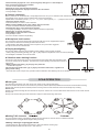
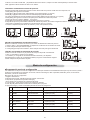
Ŷ006,FRGHSURJUDPPLQJ
The 9-dlglt MMSI (Maritime Service Identity: DSC self ID) code can be programmed at power ON.
1.Rotate [VOL] to turn power OFF.
2.While pushing and holding [DSC], turn power ON to enter MMSI code pro-gramming condition.
3.After the display appears, release [DSC], a cursor starts blinking.
(GLWWKHVSHFLILHG006,FRGHE\SXVKLQJ>Ÿ@RU>ź@
•Push [16] or [CH/WX] to move the cursor forward or backward, respec¬tively.
5.Input 9-digit code, then push [DSC] to set the code.
•Returns to the normal operation.
Note:
•This code programming can be performed only twice. After the code pro-gramming, it can be changed only by your dealer or distributor.
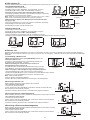
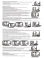
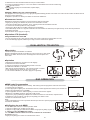
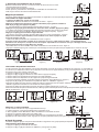
Ŷ006,FRGHFKHFN
The 9-digit MMSI (DSC self ID) code can be checked.
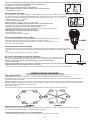
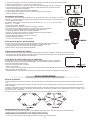
1.Push [DSC] to enter the DSC menu.
(Image1)
3.Check the 9-dlglt MMSI (DSC self ID) code.
• The MMSI code is displayed and scrolls at the channel comment indicator.(Image2)
4.Push [DSC] to return to the normal operation
DSC OPERATION
DUAL-WATCH / TRI-WATCH
(Image1) (Image2)
06

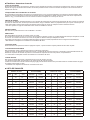
Ŷ'6&DGGUHVV,'
A total of 30 DSC address IDs (9-digit) can be programmed and named with up to 5 characters.
Ƈ3URJUDPPLQJDGGUHVV,'
1.Push [DSC] to enter the DSC menu.
(Image1)
(Image2)
3XVK>Ÿ@RU>ź@WRLQSXWGLJLWRIWKHDSSURSULDWHDGGUHVV,'
• Push [16] or [CH/WX] to move the cursor forward or backward, respectively.
• Push [SCAN] to cancel and exit the condition.
Note: 1*digit "0” is fixed fora group ID. When you input 1*digt “O’ and other 8
digits, the ID is automatically registered as a group ID. (Image3)
5.After Inputting 9-dlglt ID, push [DSC] to Input 5 characters ID name
XVLQJ>Ÿ@RU>ź@
•Push [16] or [CH/WX] to move the cursor forward or backward, respectively.
•Push [SCAN] to cancel and exit the condition.
6.Push [DSC] to program and exit the DSC menu.
Ƈ'HOHWLQJDGGUHVV,'
1.Push [DSC] to enter the DSC menu.
(Image4)
3XVK>Ÿ@RU>ź@WRVHOHFW³'(/¶DQGSXVK>'6&@
• When no address ID is programmed, “NO ID “is displayed. (Image5)
(Image6)
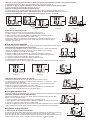
Ŷ'LVWUHVVFDOO
A Distress call should be transmitted if, in the opinion of the master, the ship or a person is in distress and requires immediate assistance.
Note: Never use the Distress call when your ship or a person is not in an emergency. A Distress call can be used only when immediate help
is needed.
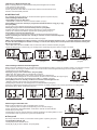
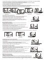
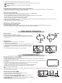
Ƈ7UDQVPLWWLQJD'LVWUHVVFDOO
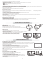
1.While opening the key cover, push [DISTRESS] for 5 sec. to
transmit the Distress call.
• Emergency channel (Channel 70) Is automatically selected and
the Distress call is transmitted. (Image7)
2.After transmitting the call, the transceiver waits for an
acknowledgment call on Channel 70.
•The Distress call is automatically transmitted about every 4 minutes.
•“DSC REPEAT" scrolls at the channel comment indicator.(Image8)
3.After receiving the acknowledgment, reply using the microphone.
• "RCV DISTRESS ACK* scrolls at the channel comment indicator.
4.Push and hold [DISTRESS] for 5 sec. to transmit a re-newed Distress call, if desired.
5.Push any key except [DISTRESS] to cancel the 'call repeat’ mode.
Note: A distress alert contains:
•Kinds of distress: Undesignated distress
•Position data: GPS position data held until receiving an ‘acknowledgement.
Ƈ5HFHLYLQJD'LVWUHVVFDOO
While monitoring Channel 70 and a Distress call is received:
1.The emergency alarm sounds.
• Push any key to stop the alarm.
2.“DSC” appears and “RCV DISTRESS’ scrolls at the channel comment indi-cator,
then Channel 16 Is automatically selected.
3.Continue monitoring Channel 16 as a coast station may require assistance.
Ƈ5HFHLYLQJD'LVWUHVVDFNQRZOHGJHPHQW
While monitoring Channel 70 and a Distress acknowledgement to other ship is received:
1.The emergency alarm sounds.
•Push any key to stop the alarm
2.‘DSC’ appears and “RCV DISTRESS ACK’ scrolls at the channel comment Indicator,
then Channel 16 Is automatically selected.
(Image1) (Image2)
(Image3)
(Image4) (Image5) (Image6)
(Image7) (Image8)
07

Ƈ5HFHLYLQJD'LVWUHVV5HOD\FDOO
While monitoring Channel 70 and a Distress Relay acknowledgement is received:
1.The emergency alarm sounds.
• Push any key to stop the alarm.
2."DSC” appears and “RCV RELAY”scrolls at the channel comment indicator, then
Channel 16 is automatically selected.
Ŷ,QGLYLGXDOFDOO
The Individual call function allows you to transmit a DSC signal to a specific ship only.
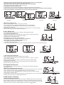
Ƈ7UDQVPLWWLQJ,QGLYLGXDOFDOO
1.Push [DSC] to enter the DSC menu.
• “INDIVIDUAL* scrolls at the channel comment indicator.(Image1)
3XVK>'6&@WRVHOHFWWKHGHVLUHGSUHSURJUDPPHGLQGLYLGXDODGGUHVVXVLQJ>Ÿ@RU>ź@
then push [DSC].
•The ID code for the Individual call must be set In advance.(Image2)
3XVK>Ÿ@RU>ź@WRVHOHFWDGHVLUHGLQWHUVKLSFKDQQHOSXVK>'6&@
•Intership channels are already preset into the transceiver in recommended order.
•Channel 70 is selected and "READY” appears after pushing [DSC].(Image3)
4.Push [DSC] to transmit the Individual call.
• If Channel 70 Is busy, the transceiver stands by until the channel becomes(Image4)
5.After transmitting the Individual call, standby on Channel 70 until an acknowledgement
is received.
• "WAIT ACK” scrolls at the channel comment Indicator.(Image5)
6.When the acknowledgement “Able to comply” is received, the specified channel (in step ) is selected with beeps automatically.
Or, when the acknowledgement ‘Unable to comply” Is received, the display returns to the operated channel (before entering the
DSC menu) with beeps.
• "RCV ABLE ACK" OR "RCV UNABLE ACK” scrolls at the channel comment indicator.(Image6)
7.Push and hold [PTT] to communicate your message to the responding ship when ‘Able to comply' is received.
Ƈ7UDQVPLWWLQJ,QGLYLGXDODFNQRZOHGJHPHQW
When receiving an Individual call, you can transmit an acknowledgement (‘Able to comply1”or ‘Unable to comply”) by using the on screen
prompts (refer to "Receiving an Individual call”). You can also send an acknowledgement through the menu system as follows.
1.Push [DSC] to enter the DSC menu.
3XVK>Ÿ@RU>ź@WRVHOHFW³,1'9$&.´DQGSXVK>'6&@
•"INDV ACK* item appears after an Individual call is received.
•"INDV ACK” item disappears if another call is received after the Individual call.
•The Individual acknowledgement can be transmitted to the last received Individual call only.(Image7)
Image8)
4.Push [DSC] to enter the standby condition for Individual acknowledgement call.
• "READY” appears at the channel comment indicator.(Image9)
5.Push [DSC] to transmit the acknowledgement to the selected station.(Image10)
6.After the Individual acknowledgement has been transmitted, the display changes to the channel specified by the calling station
automatically when “ABLE* is selected.(Image11)
Ƈ5HFHLYLQJDQ,QGLYLGXDOFDOO
While monitoring Channel 70 and an Individual call Is received:
1.The emergency alarm or beeps sound depending on the received category.
2."DSC* appears and *RCV INDIVIDUAL’ scrolls at the channel comment indicator.
3.Push any key to stop beep.
4.Push [DSC] to reply the call and select the channel specified by the calling station for voice
communication; Push any other key to ignore the Individual call.
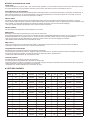
Ŷ*URXSFDOO
The Group call function allows you to transmit a DSC signal to a specific group only.
Ƈ7UDQVPLWWLQJ*URXSFDOO
1.Push [DSC] to enter the DSC menu.
(Image1)
(Image2)
(Image3) (Image4) (Image5) (Image6)
(Image7)
(Image8) (Image9) (Image10) (Image11)
08

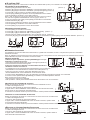
3XVK>Ÿ@RU>ź@WRVHOHFWWKHGHVLUHGSUHSURJUDPPHGJURXSDGGUHVVDQGSXVK>'6&@
• The ID code for the Group call must be set in advance.(Image1)
3XVK>Ÿ@RU>ź@WRVHOHFWWKHGHVLUHGLQWHUVKLSFKDQQHODQGSXVK>'6&@
• Channel 70 is selected and "READY” appears.(Image2)
5.Push [DSC] to transmit the Group call.
• If Channel 70 Is busy, the transceiver stands by until the channel become clear.(Image3)
6. After the Group call has been transmitted, the display changes to the previously specified channel.(Image4)
7. Push and hold [PTT] to communicate your message to the responding ship.
Ƈ5HFHLYLQJD*URXSFDOO
While monitoring Channel 70 and a Group call is received:
1.The emergency alarm or beeps sound depending on the received category.
2.“DSC" appears and “RCV GROUP" scrolls at the channel comment indicator.
3.Push any key to stop beep.
4.Push [DSC] to select the channel specified by the calling station for voice communication;
Push any other key to ignore the Group call.(Image5)
Ŷ$//6KLSVFDOO
The All Ships call function allows you to transmit a DSC signal to all ships
Ƈ7UDQVPLWWLQJ$OO6KLSVFDOO
Large ships use Channel 70 as their ‘listening channel’. When you want to announce a
message to these ships, use the ‘All Ships call’ function.
1.Push [DSC] to enter the DSC menu.
(Image6)
3.Push [DSC] to enter the standby condition for All Ships call.
• Channel 70 is selected and “READY” appears.(Image7)
4. Push [DSC] to transmit the All Ships call.
• Low power is selected(Image8)
5. After the All Ships call has been transmitted, the display changes to Channel 16 automatically.(Image9)
Ƈ5HFHLYLQJDQ$OO6KLSVFDOO
While monitoring Channel 70 and an All Ships call is received:
1.The emergency alarm sounds when the category is 'Distress’ or ’Urgency’; 2 beeps
sound for other categories.
2.“DSC” appears and "RCV ALL SHIPS” scrolls at the channel comment indicator.
3.Push any key to stop beep.
4.Push [DSC] to monitor channel 16 for an announcement from the calling vessel,
push any other key to ignore the call.
Ŷ*HRJUDSKLFDO$UHDFDOO
The Geographical Area call function allows you to transmit a DSC signal to all ships in
a geographical area.
Ƈ5HFHLYLQJD*HRJUDSKLFDO$UHDFDOO
While monitoring Channel 70 and a Geographical Area call (for the area you are in) is received:
1.The emergency alarm or beeps sound depending on the received category.
2."DSC” appears and “RCV GEOGRAPHICAL" scrolls at the channel comment Indicator.
3. Push any key to stop the beep.
4.Push [DSC] to change to the channel specified by the calling station for voice communication;
Push any other key to ignore the Geographical Area call.
Ŷ*363RVLWLRQLQGLFDWLRQ
Ƈ*363RVLWLRQLQJ,QVWUXFWLRQV
The radio with built-in GPS receiver, when the number of satellites which GPS received and the
signal strength is sufficient, then it will be able to indicate the positioning information of the ship.
When on standby mode, press and hold [DSC] for 1 second, the screen displays the positioning
information of the current ship : Latitude,longitude, UTCtime,number of satellites.
(Image1) (Image2) (Image3) (Image4)
(Image5)
(Image6)
(Image7) (Image8) (Image9)
09

SET MODE
•When the GPS signal is not received, and screen displays "NO POSITION”,please check whether the radio is blocked by obstructions.
•GPS" flashes when GPS data is invalid.
Ƈ7UDQVPLWWLQJ3RVLWLRQ5HTXHVWFDOO
Transmit a Position Request call when you want to know a specified ship’s current position, etc.
1.Push [DSC] to enter the DSC menu.
(Image1)
3XVK>Ÿ@RU>ź@WRVHOHFWWKHGHVLUHGSUHSURJUDPPHGLQGLYLGXDODGGUHVV
• The ID code tor position request must be set in advance.(Image2)
4.Push [DSC] to enter the standby condition for Position Request call.
• Channel 70 is selected and "READY" appears.(Image3)
5. Push [DSC] to transmit the Position Request call.(Image4)
6. After the Position Request call has been transmitted, the following indication is displayed.
• “WAIT ACK" scrolls at the channel comment indicator.(Image5)
7. Push any key to exit the condition and return to the normal operation.
Ƈ5HFHLYLQJD3RVLWLRQ5HTXHVWFDOO
While monitoring Channel 70 and a Position Request call is received:
1. “DSC" appears and "RCV POS REQUEST scrolls at the channel comment indicator.
2. Push any key to stop the beep.
3. Push [DSC] to reply to the call; Push any other key to ignore the call.
Ƈ5HFHLYLQJD3RVLWLRQ5HSO\FDOO
While monitoring Channel 70 and a Position Reply call is received:
1. 'DSC" and “POS REPLY" appear in the display.
» The ‘Latitude' and ‘Longitude' from the called station Is displayed and scrolled
automatically in order of Latitude co-ordinates and then Longitude co-ordinates.
2.Push any key to stop the beep
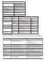
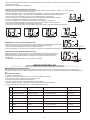
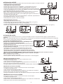
Ŷ6HWPRGHSURJUDPPLQJ
Set mode is used to change the conditions of the transceiver's functions: Scan type (Normal or Priority), Scan resume timer, Weather alert,
Dual/Tri-watch, DSC watch, Beep tone, Auto acknowledgement and Favorite channel function.
Set mode operation
1.Turn power OFF.
2.While pushing [16], tum power ON to enter Set mode.
3.After the display appears, release [16].
• "SCAN” appears at the channel comment indicator.
4.Push [16] to select the desired item, if necessary.
6.Tum power OFF, then ON again to exit Set mode.
No. Display Item Option Default
1
2
3
4
5
6
7
8
SCAN
TIMER
WX ALERT
DUAL
DSC WATCH
BEEP
AUTO ACK
FAVORITE CH
Scan type
Scan resume timer
Weather alert
Dual/Tri-watch
DSC watch
Beep tone
Auto
Favorite channel
n- (normal scan)
of (OFF)/on (ON)
of (OFF)/on (ON)
d-(Dualwatch) /1-
of (OFF)/on (ON)
of (OFF)/on (ON)
of (OFF)/on (ON)
of (OFF)/on (ON)
n- (normal scan)
of (OFF)
of (OFF)
d-(Dualwatch)
of (OFF)
on (ON)
of (OFF)
on (ON)
(Image1)
(Image2) (Image3) (Image4) (Image5)
10

Ŷ6HWPRGHLWHPV
Ƈ6FDQW\SH
The transceiver has 2 scan types: Normal scan and Priority scan. Normal scan searches all TAG channels in the selected channel group.
Priority scan searches all TAG channels In sequence while monitoring Channel 16.
Ƈ6FDQUHVXPHWLPHU
The scan resume timer can be selected as a pause (OFF) or timer scan (ON). When OFF is selected, the scan pauses until the signal
disappears. When ON is selected, the scan pauses 5 sec. and resumes even if a signal has been received on any other channel than
Channel16
Ƈ:HDWKHUDOHUW
A NOAA broadcast station transmits a weather alert tone before important weather information. When the weather alert function is turned
ON, the trans¬ceiver detects the alert, then the “WX ALT" indicator blinks until the transceiver is operated. The previously selected (used)
weather channel Is checked any time while scanning.
•“WX ALT” appears instead of “WX” indication when the function is set ON.
Ƈ'XDO7ULZDWFK
This item can be selected as Dualwatch orTri-watch.
Ƈ'6&ZDWFK
DSC watch monitors Channel 70 while you are receiving another channel.
If a distress signal is received on Channel 70, the transceiver monitors Channel 16 and 70 alternately until the distress signal disappears. If
a signal Is received on another channel, DSC watch pauses until the signal disappears.
•This function may not be available for some channel groups depending on dealer setting.
•“DSC WATCH’ scrolls at the channel comment indicator.
Ƈ%HHSWRQH
You can select silent operation by turning beep tones OFF or you can have con-firmation beeps sound at the push of a key by turning beep
tones ON.
Ƈ$XWRPDWLFDFNQRZOHGJHPHQW
This item sets the Automatic acknowledgement function ON or OFF.
When Position Request call or Position Report call Is received, transceiver au-tomatically transmits Position Request Reply call or Position
Report Reply call, respectively.
• "AUTO ACK" scrolls at the channel comment indicator.
Ƈ)DYRULWHFKDQQHO
This item sets the Favorite channel function ON or OFF.
The favorite channel is programmed by the TAG channel setting.
group in sequence when pushed.
• "FAVORITE CH " scrolls at the channel comment indicator.
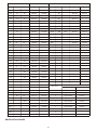
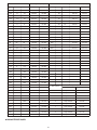
Ŷ&+$11(//,67
01A
03A
OSA
06
OTA
08
09
10
11
01
02
03
04
05
06
07
08
09
10
11
01
02
03
04A
05A
06
07A
08
09
10
11
156.050
156.050
156.100
156.150
156.150
158.200
156.200
156.250
156.250
156.300
156.350
156.350
156.400
158.450
156.500
156.550
160.650
156.050
160.700
160.750
156.150
160.800
156.200
160.850
156.250
156.300
160.950
156.350
156.400
156.450
156.500
156.550
21A
22A
23A
24
25
26
27
28
21
22
23
24
25
26
27
28
60
61
21
21A
21b
22A
23
24
25
25b
26
27
28
28b
60
157.050
157.050
157.100
157.100
157.150
157.150
157.200
157.250
157.300
157.350
157.400
156.025
156.075
161.650
157.050
161.650
161.700
157.100
161.750
157.150
161.800
161.850
161.850
161.900
161.950
162.000
162.000
160.625
160.675
Channel number Channel numberFrequency(MHz) Frequency(MHz)
USA INT CAN Transmit Receive USA INT CAN Transmit Receive
Only
receiver
Only
receiver
Only
receiver
11

12
13"2
14
15*2
18
ir
18A
19A
20
20A
12
13
14
15*1
18
17
18
19
20
12
13*’
14
15*’
16
1F’
18A
19A
20'1
156.600
156.650
156.700
156.750
158.800
156.850
156.900
156.900
156.950
156.950
157.000
157.000
156.600
156.650
156.700
158.750
156.800
156.850
161.500
156.900
161.550
156.950
161.600
157.000
61A
63A
64A
65A
66A
87’
62
63
64
65
65A
66
66A
67
61A
62A
64
64A
65A
66A*1
67
156.075
156.125
156.125
156.175
156.175
156.225
156.225
156.275
156.275
156.325
156.325
156.375
156.075
160.725
156.125
160.775
156.175
160.825
156.225
160.875
156.275
160.925
156.325
156.375
Channel number Channel numberFrequency(MHz) Frequency(MHz)
USA INT CAN Transmit Receive USA INT CAN Transmit Receive
68
69
7(P
71
72
73
74
75*1
76*1
77*1
78A
79A
80A
68
69
7(T
71
72
73
74
75*1
76*1
77
78
79
80
68
69
70*3
71
72
73
74
75*1
76*1
77*1
78A
79A
80A
156.425
156.475
156.525
156.575
156.625
156.675
156.725
156.775
156.825
156.875
156.925
156.925
156.975
156.975
157.025
157.025
156.425
156.475
156.525
156.575
156.625
156.675
156.725
156.775
156.825
156.875
161.525
156.925
161.575
156.975
161.625
157.025
86A
87
87A
88
88A
87
88
87
88
157.325
157.375
157.375
157425
157.425
157.325
181.975
157.375
162.025
157425
81A
82A
83A
84
84A
85
85A
86
81
82
83
84
85
86
81A
82A
83
83A
83b
84
85
86
157.075
157.075
157.125
157.125
157.175
157.175
157.225
157.225
157.275
157.275
157.325
161.675
157.075
161.725
157.125
161.775
157.175
161.775
161.825
157.225
161.875
157.275
161.925
1
2
3
4
5
6
7
8
9
10
WX channel
Transmit
Only receiver
Only receiver
Only receiver
Only receiver
Only receiver
Only receiver
Only receiver
Only receiver
Only receiver
Only receiver
Receive
162.550
162.400
162.475
162.425
162.450
162.500
162.525
161.650
161.775
163.275
Frequency(MHz)
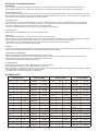
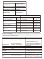
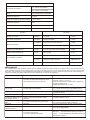
Ŷ63(&,),&$7,216
12

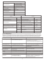
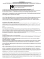
Ŷ7528%/(6+227,1*
Issues described in the following table are some common operational failure. These types of errors are generally due to improperly
connected, the operation caused by incorrect settings, or operator error caused due to incomplete programming. These problems are
usually not caused by circuit failure. Before suspect intercom failure, please refer to the relevant parts of these forms and the instructions for
use.
Transmitter Receiver
25W/1W
±5.0 kHz
2K
Sensitivity
Squelch sensitivity
Adjacent channel selectivity
Spurious response rejection ratio
Intermodulation rejection ratio
Max. current
Audio output power
GPS signal ver.
Output Impendence
NMEA0183-2.0
4
Output power
Max. frequency deviation
Adjacent channel power
Audio harmonic distortion
Input resistance
General
Mode
Frequency stability
Operating temperature range
Antenna impedance
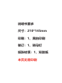
Dimensions (WxDxH)
Weight (main unit)
TX: 156.025-157.425 MHz
RX: 156.050 -163.275 MHz
FM (16K0G3E) DSC (16K0G2B)
±10ppm
-20°C - +60°C
50
153mmx152mmx67mm
742g (with microphone)
Frequency coverage
Current drain
Spurious emissions
Question Possible Cause Solutions
1,check the power cable is connected correctly: red
(+); black (-).
2,then find the cause of blown fuse, replace the
fuse current to 15A.
3,adjust the power supply is 13.8V.
1, check the connections are correct.
2. external GPS format should be NMEA0183-2.0.
The channel you want to scan is set to mark
channels.
Exit the weather channel or 70 channels.
Choose other channels.
1,select a channel.
2,the channel is set to the same frequency.
Open the beep function in the settings mode.
Hold down the [DSC] key to boot into MMSI setting
mode.
1,rotate [SQL] knob to adjust the squelch level.
2,rotate [VOL] knob to adjust the volume.
3,ths use of vibration drainage water discharge.
1.the power cable is connected well.
2.the power cable fuse broken.
3.the voltage exceeds 17V or below 9V.
1.connection error.
2.different external GPS format.
Not set mark channels (TAG).
Work on the weather channel or 70 channels.
Some channels can transmit at low power.
1,the channel is different frequency (DUP).
2,the working group on its own channel.
Beep off
MMSI code is not set.
1. tone squelch level too.
2. the volume Is too small.
3. the speaker grid water.
Power did not respond.
Unable to connect with
GPS.
Can not be scanned.
Can not launch.
High power can not be
selected.
The same channel can
not talk.
No beep
Can not transmit a
distress call.
No sound from the
speaker.
13

WARNING
RF ENERGY EXPOSURE AND PRODUCT SAFETY GUIDE FOR TWO-WAY RADIOS
• User instructions should accompany the device when transferred to other users.
• Do not use this device if the operational requirements described herein are not met.
This two-way radio uses electromagnetic energy in the radio frequency (RF) spectrum to provide communications between two or more
users over a distance. RF energy, which when used improperly, can cause biological damage.
All Retevis two-way radios are designed, manufactured, and tested to ensure they meet government-established RF exposure levels. In
addition, manufacturers also recommend specific operating instructions to users of two-way radios. These instructions are important
because they inform users of RF energy exposure and provide simple procedures on how to control it.
Please refer to the following websites for more information on what RF energy exposure is and how to control your exposure to assure
compliance with established RF exposure limits: http://www.who.int/en/
When two-way radios are used as a consequence of employment, the Local Government Regulations requires users to be fully aware of
and able to control their exposure to meet occupational requirements. Exposure awareness can be facilitated by the use of a product label
directing users to specific user awareness information. Your Retevis two-way radio has a RF Exposure Product Label. Also, your Retevis
user manual, or separate safety booklet includes information and operating instructions required to control your RF exposure and to satisfy
compliance requirements.
Radio License(only applicable to licensed radio)
Governments keep the radios in classification, business two-way radios operate on radio frequencies that are regulated by the local radio
management departments (FCC, ISED, OFCOM, ANFR, BFTK, Bundesnetzagentur...).To transmit on these frequencies, you are required
to have a license issued by them. The detailed classification and the use of your two radios, please contact the local government radio
management departments.
Use of this radio outside the country where it was intended to be distributed is subject to government regulations and may be prohibited.
Unauthorized modification and adjustment
Changes or modifications not expressly approved by the party responsible for compliance may void the user’s authority granted by the local
government radio management departments to operate this radio and should not be made. To comply with the corresponding requirements,
transmitter adjustments should be made only by or under the supervision of a person certified as technically qualified to perform transmitter
maintenance and repairs in the private land mobile and fixed services as certified by an organization representative of the user of those
services.
Replacement of any transmitter component (crystal, semiconductor, etc.) not authorized by the local government radio management
departments equipment authorization for this radio could violate the rules.
FCC Requirements:
This device complies with part 15 of the FCC Rules. Operation is subject to the condition that this device does not cause harmful
interference. (Licensed radios are applicable);
This device complies with part 15 of the FCC Rules. Operation is subject to the following two conditions: (Other devices are applicable)
(1) This device may not cause harmful interference, and
(2) this device must accept any interference received, including interference that may cause undesired operation.
(Only Applicable to GMRS radio station):
A valid individual license is required to operate a GMRS station. To obtain an individual license, an applicant must be eligible and follow the
applicable rules and procedures established by FCC. The applicant must pay the required application and regulatory fees. Each individual
license in the GMRS will normally have a term of ten years from the date of grant or renewal, and may be renewed pursuant to the
procedures of FCC. To obtain a GMRS operator license, you need FCC Form 605 & 159, we suggest visiting the FCC website at
https://www.fcc.gov/wireless/support/fcc-form-605, which includes necessary instructions. More questions about the license application,
please contact the FCC at 1-888-225-5322 or go to the FCC's website: http://www.fcc.gov.
According to FCC rules, any individual who holds an individual license may allow his or her immediate family members to operate his or her
GMRS station or stations. Immediate family members are the licensee's spouse, children, grandchildren, stepchildren, parents,
grandparents, stepparents, brothers, sisters, aunts, uncles, nieces, nephews, and in-laws.
•(Only applicable to industrial environment)This equipment has been tested and found to comply with the limits for a Class A digital device,
pursuant to part 15 of the FCC Rules. These limits are designed to provide reasonable protection against harmful interference when the
equipment is operated in a commercial environment. This equipment generates, uses, and can radiate radio frequency energy and, if not
installed and used in accordance with the instruction manual, may cause harmful interference to radio communications. Operation of this
equipment in a residential area is likely to cause harmful interference in which case the user will be required to correct the interference at
his own expense.
•(Only applicable to home)This equipment has been tested and found to comply with the limits for a Class B digital device, pursuant to part
15 of the FCC Rules. These limits are designed to provide reasonable protection against harmful interference in a residential installation.
This equipment generates, uses and can radiate radio frequency energy and, if not installed and used in accordance with the instructions,
may cause harmful interference to radio communications. However, there is no guarantee that interference will not occur in a particular
installation. If this equipment does cause harmful interference to radio or television reception, which can be determined by turning the
equipment off and on, the user is encouraged to try to correct the interference by one or more of the following measures:
—Reorient or relocate the receiving antenna.
—Increase the separation between the equipment and receiver.
—Connect the equipment into an outlet on a circuit different from that to which the receiver is connected.
—Consult the dealer or an experienced radio/TV technician for help.
ATTENTION!
Before using this radio, read this guide which contains
important operating instructions for safe usage and RF energy
awareness and control for compliance with applicable
standards and regulations.
14

CE Requirements:
•(Simple EU declaration of conformity) Shenzhen Retevis Technology Co., Ltd. declares that the radio equipment type is in compliance with
the essential requirements and other relevant provisions of RED Directive 2014/53/EU and the ROHS Directive 2011/65/EU and the WEEE
Directive 2012/19/EU; the full text of the EU declaration of conformity is available at the following internet address: www.retevis.com.
•Restriction Information
This product can be used in EU countries and regions, including: Belgium (BE), Bulgaria (BG), Czech Republic (CZ), Denmark (DK),
Germany (DE), Estonia (EE), Ireland (IE), Greece (EL), Spain (ES), France (FR), Croatia (HR), Italy (IT), Cyprus (CY), Latvia (LV),
Lithuania (LT), Luxembourg (LU), Hungary (HU), Malta (MT), Netherlands (NL), Austria (AT), Poland (PL), Portugal (PT), Romania (RO),
Slovenia (SI), Slovakia (SK), Finland (FI), Sweden (SE) and United Kingdom (UK).
For the warning information of the frequency restriction, please refer to the package.
•Disposal
The crossed-out wheeled-bin symbol on your product, literature, or packaging reminds you that in the European Union, all
electrical and electronic products,batteries, and accumulators (rechargeable batteries) must be taken to designated collection
locations at the end of their working life. Do not dispose of these products as unsorted municipal waste. Dispose of them
according to the laws in your area.
IC Requirements:
Licence-exempt radio apparatus
This device contains licence-exempt transmitter(s)/receiver(s) that comply with Innovation, Science and Economic Development Canada’s
licence-exempt RSS(s). Operation is subject to the following two conditions:
(1) This device may not cause interference.
(2) This device must accept any interference, including interference that may cause undesired operation of the device.
Le présent appareil est conforme aux CNR d’Industrie Canada applicables aux appareils radio exempts de licence. L’exploitation est
autorisée aux deux conditions suivantes :
(1) l’appareil ne doit pas produire de brouillage;
(2) l’utilisateur de l’appareil doit accepter tout brouillage radioélectrique subi, même si le brouillage est susceptible d’en compromettre le
fonctionnement.
5)([SRVXUH&RPSOLDQFHDQG&RQWURO*XLGHOLQHVDQG2SHUDWLQJ,QVWUXFWLRQV
•Occupational/Controlled Radio, this radio is designed for and classified as “Occupational/Controlled Use Only”, meaning it must be used
only during the course of employment by individuals aware of the hazards, and the ways to minimize such hazards; NOT intended for use in
a General population/uncontrolled environment.
•General population/uncontrolled Radio, this radio is designed for and classified as “General population/uncontrolled Use”.
To control your exposure and ensure compliance with the occupational/controlled environment exposure limits, always adhere to the
following procedures. When operating in front of the face, worn on the body, always place the radio in a Retevis approved clip, holder,
holster, case, or body harness for this product. Using approved body-worn accessories is important because the use of Non-Retevis
approved accessories may result in exposure levels, which exceed the IEEE/ICNIRP RF exposure limits.
(listen), release the PTT button. Transmitting necessary information or less, is important because the radio generates measurable RF
energy exposure only when transmitting in terms of measuring for standards compliance.
•DO NOT operate the radio without a proper antenna attached, as this may damage the radio and may also cause you to exceed RF
exposure limits. A proper antenna is the antenna supplied with this radio by the manufacturer or an antenna specifically authorized by the
manufacturer for use with this radio, and the antenna gain shall not exceed the specified gain by the manufacturer declared.
to be exceeded.
•During transmissions, your radio generates RF energy that can possibly cause interference with other devices or systems. To avoid such
interference, turn off the radio in areas where signs are posted to do so.
•DO NOT operate the transmitter in areas that are sensitive to electromagnetic radiation such as hospitals, aircraft, and blasting sites.
•Portable Device, this transmitter may operate with the antenna(s) documented in this filing in Push-to-Talk and body-worn configurations.
RF exposure compliance is limited to the specific belt-clip and accessory configurations as documented in this filing and the separation
distance between head and the device or its antenna shall be at least 2.5 cm.
•Mobile Device, during operation, the separation distance between user and the antenna subjects to actual regulations, this separation
distance will ensure that there is sufficient distance from a properly installed externally-mounted antenna to satisfy the RF exposure
requirements. Transmit only when people outside the vehicle are at least the recommended minimum lateral distance away from a properly
installed according to installation instructions, externally mounted antenna.
FCC RX exposure compliance
Hand-held Mode(if applicable)
• Hold the radio in a vertical position with the microphone (and other partsof the radio including the antenna) at least 2.5 cm
(one inch) away from the nose or lips. The antenna should be kept away from the eyes. Keeping the radio at a proper
distance is important as RF exposure decreases with increasing distance from the antenna.
Phone Mode(if applicable)
•When placing or receiving a phone call, hold your radio product as you would a wireless telephone. Speak directly into the microphone. Do
not use the equipment when you are driving
Electromagnetic Interference/Compatibility
NOTE: Nearly every electronic device is susceptible to electromagnetic interference (EMI) if inadequately shielded, designed, or otherwise
configured for electromagnetic compatibility.
Avoid Choking Hazard
Small Parts. Not for children under 3 years.
15

•Turn off your radio before removing (installing) a battery or accessory or when charging battery.
•Turn off your radio when you are in a potentially hazardous environments: Near electrical blasting caps, in a blasting area,
in explosive atmospheres (inflammable gas, dust particles, metallic powders, grain powders, etc.).
•Turn off your radio while taking on fuel or while parked at gasoline service stations.
To avoid electromagnetic interference and/or compatibility conflicts
•Turn off your radio in any facility where posted notices instruct you to do so, hospitals or health care facilities (Pacemak-
ers, Hearing Aids and Other Medical Devices) may be using equipment that is sensitive to external RF energy.
•Turn off your radio when on board an aircraft. Any use of a radio must be in accordance with applicable regulations per
airline crew instructions.
• Use the lowest volume necessary to do your job.
• Turn up the volume only if you are in noisy surroundings.
• Turn down the volume before adding headset or earpiece.
• Limit the amount of time you use headsets or earpieces at high volume.
• When using the radio without a headset or earpiece, do not place the radio's speaker directly against your ear
• Use careful with the earphone maybe possible excessive sound pressure from earphones and headphones can cause
hearing loss
Note: Exposure to loud noises from any source for extended periods of time may temporarily or permanently affect
your hearing. The louder the radio's volume, the less time is required before your hearing could be affected.
Hearing damage from loud noise is sometimes undetectable at first and can have a cumulative effect.
Antennas
•Do not use any portable radio that has a damaged antenna. If a damaged antenna comes into contact with the skin when
the radio is in use, a minor burn can result.
Batteries (If appropriate)
•When the conductive material such as jewelry, keys or chains touch exposed terminals of the batteries, may complete an
electrical circuit (short circuit the battery) and become hot to cause bodily injury such as burns. Exercise care in handling
any battery, particularly when placing it inside a pocket, purse or other container with metal objects
•BATTERY WARNING: KEEP OUT OF REACH OF CHILDREN
•Store spare batteries securely
•If the battery compartment (if applicable) does not close securely, stop using the product and keep it away from children
•If you think batteries might have been swallowed or placed inside any part of the body, seek immediate medical attention
•Dispose of used batteries immediately and safely
Long transmission
•When the transceiver is used for long transmissions, the radiator and chassis will become hot.
Forbid
•Do not use charger outdoors or in moist environments, use only in dry locations/conditions.
•Do not disassemble the charger, that may result in risk of electrical shock or fire.
•Do not operate the charger if it has been broken or damaged in any way.
•Do not place a portable radio in the area over an air bag or in the air bag deployment area. The radio may be propelled
with great force and cause serious injury to occupants of the vehicle when the air bag inflates.
To reduce risk
•Pull by the plug rather than the cord when disconnecting the charger.
•Unplug the charger from the AC outlet before attempting any maintenance or cleaning.
•Contact Retevis for assistance regarding repairs and service.
•The adapter shall be installed near the equipment and shall be easily accessible
•This radio meets the RF exposure guidelines when used with the Retevis accessories supplied or designated for the
product. Use of other accessories may not ensure compliance with the RF exposure guidelines and may violate
regulations.
•For a list of Retevis-approved accessories for your radio model, visit the following website: http://www.Retevis.com
WARNING
WARNING
WARNING
WARNING
WARNING
Avoid Burns
Safety Operation
Approved Accessories
Turn off your radio power in the following conditions:
Protect your hearing:
16

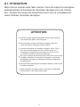
Vielen Dank für den Kauf dieses Seefunkgeräts. Sie finden das
professionelle und menschenorientierte Design des Transceivers
während des Einsatzes. Bitte lesen Sie alle Anweisungen sorgfältig
und vollständig durch, bevor Sie den Transceiver verwenden.
AN DEN BENUTZER:
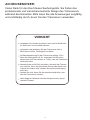
<589/).:
Verwenden Sie niemals den Notruf, wenn sich Ihr Schiff oder
ein Stift nicht in einem Notfall befindet.
Verwenden oder platzieren Sie den Transceiver nicht in
Bereichen mit Hitze, Feuchtigkeit und Staub.
Die Betriebsspannung für den Transceiver beträgt 13,8 V.
Wenn die Stromquelle 24V ist, verwenden Sie bitte einen
Stromrichter (24V konvertieren in 13,8V), oder der Transceiver
funktioniert nicht.
Niemals direkt mit AC220V verbinden, dies wird den Transce-
iver ruinieren. Wenn ein abnormaler Geruch oder Rauch vom
Transceiver erkannt wird, schalten Sie die Stromversorgung
sofort aus.
Senden Sie nicht, bevor Sie die Antenne anschließen, dies
wird den Transceiver ruinieren.
Nach längerem Gebrauch wird das Heizpanel heiß, das ist
normaler Zustand.
17
La pagina si sta caricando...
La pagina si sta caricando...
La pagina si sta caricando...
La pagina si sta caricando...
La pagina si sta caricando...
La pagina si sta caricando...
La pagina si sta caricando...
La pagina si sta caricando...
La pagina si sta caricando...
La pagina si sta caricando...
La pagina si sta caricando...
La pagina si sta caricando...
La pagina si sta caricando...
La pagina si sta caricando...
La pagina si sta caricando...
La pagina si sta caricando...
La pagina si sta caricando...
La pagina si sta caricando...
La pagina si sta caricando...
La pagina si sta caricando...
La pagina si sta caricando...
La pagina si sta caricando...
La pagina si sta caricando...
La pagina si sta caricando...
La pagina si sta caricando...
La pagina si sta caricando...
La pagina si sta caricando...
La pagina si sta caricando...
La pagina si sta caricando...
La pagina si sta caricando...
La pagina si sta caricando...
La pagina si sta caricando...
La pagina si sta caricando...
La pagina si sta caricando...
La pagina si sta caricando...
La pagina si sta caricando...
La pagina si sta caricando...
La pagina si sta caricando...
La pagina si sta caricando...
La pagina si sta caricando...
La pagina si sta caricando...
La pagina si sta caricando...
La pagina si sta caricando...
La pagina si sta caricando...
La pagina si sta caricando...
La pagina si sta caricando...
La pagina si sta caricando...
La pagina si sta caricando...
La pagina si sta caricando...
La pagina si sta caricando...
La pagina si sta caricando...
La pagina si sta caricando...
La pagina si sta caricando...
La pagina si sta caricando...
La pagina si sta caricando...
La pagina si sta caricando...
La pagina si sta caricando...
La pagina si sta caricando...
La pagina si sta caricando...
La pagina si sta caricando...
La pagina si sta caricando...
La pagina si sta caricando...
La pagina si sta caricando...
La pagina si sta caricando...
La pagina si sta caricando...
La pagina si sta caricando...
La pagina si sta caricando...
La pagina si sta caricando...
La pagina si sta caricando...
La pagina si sta caricando...
-
 1
1
-
 2
2
-
 3
3
-
 4
4
-
 5
5
-
 6
6
-
 7
7
-
 8
8
-
 9
9
-
 10
10
-
 11
11
-
 12
12
-
 13
13
-
 14
14
-
 15
15
-
 16
16
-
 17
17
-
 18
18
-
 19
19
-
 20
20
-
 21
21
-
 22
22
-
 23
23
-
 24
24
-
 25
25
-
 26
26
-
 27
27
-
 28
28
-
 29
29
-
 30
30
-
 31
31
-
 32
32
-
 33
33
-
 34
34
-
 35
35
-
 36
36
-
 37
37
-
 38
38
-
 39
39
-
 40
40
-
 41
41
-
 42
42
-
 43
43
-
 44
44
-
 45
45
-
 46
46
-
 47
47
-
 48
48
-
 49
49
-
 50
50
-
 51
51
-
 52
52
-
 53
53
-
 54
54
-
 55
55
-
 56
56
-
 57
57
-
 58
58
-
 59
59
-
 60
60
-
 61
61
-
 62
62
-
 63
63
-
 64
64
-
 65
65
-
 66
66
-
 67
67
-
 68
68
-
 69
69
-
 70
70
-
 71
71
-
 72
72
-
 73
73
-
 74
74
-
 75
75
-
 76
76
-
 77
77
-
 78
78
-
 79
79
-
 80
80
-
 81
81
-
 82
82
-
 83
83
-
 84
84
-
 85
85
-
 86
86
-
 87
87
-
 88
88
-
 89
89
-
 90
90


in altre lingue
- English: Retevis RM20 User manual
- français: Retevis RM20 Manuel utilisateur
- español: Retevis RM20 Manual de usuario
- Deutsch: Retevis RM20 Benutzerhandbuch
Altri documenti
-
ICOM IC-M127EURO Manuale del proprietario
-
Furuno FM4800 Manuale utente
-
-
Kenwood NX-5000 Manuale utente
-
-
-
Raymarine Ray 106 Manuale utente
-
-
Cobra MR HH150 FLT Manuale del proprietario
-
Standard Horizon CMP31 Manuale del proprietario